EP0287224A2 - Méthode d'élimination des émissions de NOx et de SOx des systèmes de combustion en utilisant des composants contenant de l'azote - Google Patents
Méthode d'élimination des émissions de NOx et de SOx des systèmes de combustion en utilisant des composants contenant de l'azote Download PDFInfo
- Publication number
- EP0287224A2 EP0287224A2 EP88302535A EP88302535A EP0287224A2 EP 0287224 A2 EP0287224 A2 EP 0287224A2 EP 88302535 A EP88302535 A EP 88302535A EP 88302535 A EP88302535 A EP 88302535A EP 0287224 A2 EP0287224 A2 EP 0287224A2
- Authority
- EP
- European Patent Office
- Prior art keywords
- approximately
- zone
- nitrogen oxides
- combustion
- effluent streams
- Prior art date
- Legal status (The legal status is an assumption and is not a legal conclusion. Google has not performed a legal analysis and makes no representation as to the accuracy of the status listed.)
- Granted
Links
Images


Classifications
-
- B—PERFORMING OPERATIONS; TRANSPORTING
- B01—PHYSICAL OR CHEMICAL PROCESSES OR APPARATUS IN GENERAL
- B01D—SEPARATION
- B01D53/00—Separation of gases or vapours; Recovering vapours of volatile solvents from gases; Chemical or biological purification of waste gases, e.g. engine exhaust gases, smoke, fumes, flue gases, aerosols
- B01D53/34—Chemical or biological purification of waste gases
- B01D53/46—Removing components of defined structure
- B01D53/60—Simultaneously removing sulfur oxides and nitrogen oxides
-
- B—PERFORMING OPERATIONS; TRANSPORTING
- B01—PHYSICAL OR CHEMICAL PROCESSES OR APPARATUS IN GENERAL
- B01D—SEPARATION
- B01D53/00—Separation of gases or vapours; Recovering vapours of volatile solvents from gases; Chemical or biological purification of waste gases, e.g. engine exhaust gases, smoke, fumes, flue gases, aerosols
- B01D53/34—Chemical or biological purification of waste gases
- B01D53/46—Removing components of defined structure
- B01D53/54—Nitrogen compounds
- B01D53/56—Nitrogen oxides
-
- F—MECHANICAL ENGINEERING; LIGHTING; HEATING; WEAPONS; BLASTING
- F02—COMBUSTION ENGINES; HOT-GAS OR COMBUSTION-PRODUCT ENGINE PLANTS
- F02B—INTERNAL-COMBUSTION PISTON ENGINES; COMBUSTION ENGINES IN GENERAL
- F02B2275/00—Other engines, components or details, not provided for in other groups of this subclass
- F02B2275/14—Direct injection into combustion chamber
-
- Y—GENERAL TAGGING OF NEW TECHNOLOGICAL DEVELOPMENTS; GENERAL TAGGING OF CROSS-SECTIONAL TECHNOLOGIES SPANNING OVER SEVERAL SECTIONS OF THE IPC; TECHNICAL SUBJECTS COVERED BY FORMER USPC CROSS-REFERENCE ART COLLECTIONS [XRACs] AND DIGESTS
- Y02—TECHNOLOGIES OR APPLICATIONS FOR MITIGATION OR ADAPTATION AGAINST CLIMATE CHANGE
- Y02A—TECHNOLOGIES FOR ADAPTATION TO CLIMATE CHANGE
- Y02A50/00—TECHNOLOGIES FOR ADAPTATION TO CLIMATE CHANGE in human health protection, e.g. against extreme weather
- Y02A50/20—Air quality improvement or preservation, e.g. vehicle emission control or emission reduction by using catalytic converters
-
- Y—GENERAL TAGGING OF NEW TECHNOLOGICAL DEVELOPMENTS; GENERAL TAGGING OF CROSS-SECTIONAL TECHNOLOGIES SPANNING OVER SEVERAL SECTIONS OF THE IPC; TECHNICAL SUBJECTS COVERED BY FORMER USPC CROSS-REFERENCE ART COLLECTIONS [XRACs] AND DIGESTS
- Y02—TECHNOLOGIES OR APPLICATIONS FOR MITIGATION OR ADAPTATION AGAINST CLIMATE CHANGE
- Y02T—CLIMATE CHANGE MITIGATION TECHNOLOGIES RELATED TO TRANSPORTATION
- Y02T10/00—Road transport of goods or passengers
- Y02T10/10—Internal combustion engine [ICE] based vehicles
- Y02T10/12—Improving ICE efficiencies
Definitions
- the present invention is related to methods for reducing nitrogen oxide (“NO x ”) emissions from pollution sources, such as combustion systems. More particularly, the present invention relates to the noncatalytic, selective reduction of NO x by -NH and -CN containing compounds to achieve very low levels of NO x emissions.
- NO x nitrogen oxide
- Air pollution can take various forms. Some of the different types of air pollutants include particulate emissions such as coal ash, partially burned coal particles, and the like, sulfur compounds such as SO2 and SO3 (sometimes collectively referred to as “SO x "), ozone, carbon oxide emissions, volatile hydrocarbon emissions, and emissions of nitrogen oxides (commonly referred to collectively as “NO x "). Pollution sources include automobiles, industrial plants, small commercial establishments, such as dry cleaners and service stations, and even nature itself.
- Air pollution is known to aggravate certain medical conditions (such as heart and lung problems) and is known to cause problems in the environment, ranging from corrosion to acid rain.
- Nitrogen dioxide which is brown in color, undergoes a series of reactions, known generally as “photochemical smog formation,” in the presence of sunlight and airborne hydrocarbons. These reactions result in a marked decline in overall air quality.
- NO2 is produced from a wide variety of pollution sources, its primary source is from nitric oxide (“NO") released into the air. NO is commonly formed during combustion processes, including internal combustion engines in automobiles, hydrocarbon fuel power plants, process furnaces, incinerators, coal-fired utility boilers, glass furnaces, cement kilns, oil field steam generators, gas turbines, and other similar installations.
- NO nitric oxide
- N2 molecular nitrogen
- fuels which contain large amounts of nitrogen chemically bound within the fuel structure may produce significant NO x emissions as a result of the oxidation of the fuel nitrogen during the burning process.
- This source of NO x emission (often termed “fuel NO x ”) is the predominant source of NO x with the combustion of coal, heavy oils, biological and agricultural residues, and some municipal, industrial, and agricultural wastes.
- NO is the only oxide of nitrogen which is stable at the high temperatures encountered in these types of combustion processes, NO is the predominant nitrogen emission product. At normal atmospheric temperatures, however, the equilibrium between NO and NO2 favors NO2. Hence, NO formed by combustion is generally discharged into the atmosphere as NO, and only subsequently converted to NO2. In order to control NO2 emissions, therefore, it is necessary to eliminate NO before it enters the atmosphere.
- Fuel NO x formation is most easily controlled by limiting the amount of oxygen present during the period in which the nitrogen species are being evolved from the fuel matrix. Techniques such as a staged combustion, overfire air addition, and “burners out of service” all use this concept to limit fuel and nitrogen oxidation.
- An alternative approach for removing NO from flue gases and other streams of pollutants is to reduce NO to nitrogen and water, which may then be discharged to the atmosphere. Reduction of NO x may be accomplished with or without catalytic assistance. Practically, the noncatalytic processes are preferable because they are not subject to the usual disadvantages of employing catalysts. Some of these additional disadvantages include higher expense associated with the catalyst, the potential of catalyst plugging, the expense and difficulty of contacting the combustion effluents with the catalyst, and the danger that the catalyst will disintegrate and be emitted into the atmosphere.
- NO x reduction processes often teach the removal of NO x from flue gases by reduction of the NO by the addition of ammonia, urea, or ammonia precursors, alone or in combination with some other combustional material, while the waste gas is at a relatively high temperature (generally from about 700°C to about 1200°C).
- cyanuric acid could possibly serve as a species for reducing NO x .
- Perry, et al. "Rapid Reduction of Nitrogen Oxides in Exhaust Gas Streams," Nature pp. 657-658 (December 1986) (hereinafter "Perry Process”).
- isocyanuric acid produced by decomposing cyanuric acid
- Perry further reports "the absence of the need for controlled amounts of oxygen.” While that process reportedly showed some possible benefits for use in reducing the level of NO x emission in the laboratory setting, the reported results have not been duplicated in actual combustion application.
- SO x sulfur oxides
- SO2 sulfur dioxide
- SO3 sulfur trioxide
- the present invention relates to methods for selectively reducing NO x so that nitrogen oxides can be removed from emission effluent streams and NO x emissions can be reduced to very low levels.
- the present invention teaches a method whereby NO x and SO x may be simultaneously removed from the effluent stream.
- the present invention teaches the reduction of NO x with NH3, urea, cyanuric acid, and related compounds. Contrary to the teachings of the existing literature, however, the present invention teaches a two-step reaction process under carefully controlled conditions for reducing NO x to very low levels.
- the selective reducing agent such as ammonium sulfate, urea, or cyanuric acid
- the selective reducing agent such as ammonium sulfate, urea, or cyanuric acid
- this decomposition forms NH2 radicals.
- This reaction takes place in an oxygen-free, fuel-rich "decomposition zone.” For example, when cyanuric acid is decomposed, it is most likely to form isocyanic acid.
- the general mechanism for producing isocyanic acid from cyanuric acid is as follows: (HOCN)3 ⁇ 3HNCO It is presently preferred that the reaction temperature in this decomposition zone be maintained in the range of from about 300°F (150°C) to about 3000°F (1650°C), and preferably in the range of from about 1200°F (650°C) to about 1900°F (1040°C) when NH3, urea, or a related compound is the reducing agent, and preferably in the range of from about 1400°F (750°C) to about 2400°F (1300°C) when cyanuric acid is the reducing agent.
- NO x may or may not be a part of the oxygen deficient gases in the oxygen-free, fuel-rich decomposition zone. That is, the production of the reaction intermediates in the oxygen-free decomposition zone may take place within the combustion area ("combustion zone") which produces the effluents. Alternatively, reducing agent decomposition may occur at a location remote from the combustion zone in the presence of CO and water. If the second alternative is chosen, the reducing agent decomposition species will then be injected into the effluent stream at an appropriate location.
- the decomposition stream is mixed with the effluent stream containing NO x .
- the oxygen level of the stream must be carefully controlled to provide an excess of oxygen. It may be necessary at this point to inject air into the effluent stream in order to maintain the proper conditions for NO x reduction.
- NO x reduction takes place at temperatures in the range of from approximately 500°F (250°C) to approximately 2600°F (1425°C).
- the selective reduction of NO x in this zone is relatively fast; but residence times in excess of at least 30 milliseconds are preferred in order to assure that complete micromixing occurs.
- the molar ratio of equivalent nitrogen (moles of nitrogen) in the reducing agent to nitrogen in NO x to be removed should be approximately 0.5:1 to approximately 10:1. Increasing the ratio of the reducing agent to the NO x increases the extent of NO x reaction; however, it may also increase the overall cost of the control technology and the probability of undesirable trace species produced by the reaction of the reducing agent being emitted.
- the present invention can also be combined with SO x control technology.
- species used to control SO x such as limestone, dolomite, quicklime, and hydrated lime
- SO x can be added to the NO x reducing agent for injection into the effluent stream.
- simultaneous NO x and SO x control can be achieved.
- the present invention is related to a two-stage reaction method for reducing NO x within an effluent stream using -NH or -CN decomposition products.
- the effluent stream may originate with a fixed facility such as a boiler, refinery heater, industrial furnace, gas turbine, municipal waste incinerator, or internal combustion engine, or with a mobile source such as a gasoline or diesel engine in a motor vehicle.
- the present invention provides an extremely effective method of eliminating NO x pollutants.
- NO x pollutants can be reduced by more than approximately 90 percent, thereby producing exhaust NO x emission levels, under typical conditions, significantly below 100 ppm.
- the present invention operates by the use of an amine, or cyano containing selective reducing agent such as ammonium sulfate, urea, melamine, or cyanuric acid.
- an amine, or cyano containing selective reducing agent such as ammonium sulfate, urea, melamine, or cyanuric acid.
- Other potentially useful compounds include such species as ammonium carbonate, ammonium bicarbonate, ammonium formate, ammonium oxalate, ammonia, biuret, triuret, NH2CN, Ca(CN)2, CaCN2, NaOCN, and dicyanodiamide.
- urea, ammonia, and ammonia salts are known to be useful as NO x reducing agents at temperatures between 1300 and 2000°F (700 and 1100°C) for fuel-lean injection and at temperatures from 1900 to 3000°F (1040 to 1650°C) for fuel-rich injection.
- the existing art does not teach that reductions can be achieved with low temperature, fuel-rich injection and it is incapable of producing emission levels significantly below 100 ppm.
- current commercial practice is to employ selective high cost catalytic reduction processes when extremely low emission levels are required.
- the present invention overcomes the obstacles previously encountered when applying the prior art to actual practice.
- the present invention also operates by the use of cyanuric acid as an NO x reducing agent.
- cyanuric acid is not useful as an NO x reducing agent under conditions typical of actual practice without the use of a stainless steel catalyst.
- the present invention overcomes the obstacles previously encountered in applying the Perry cyanuric acid process in actual practice.
- the selective reducing agent is decomposed.
- this reaction zone can be referred to generally as the "decomposition zone" and may be within the combustion zone which produces the NO x emissions, or it may be separate. Decomposition of the selective reducing agent is necessary in order to provide appropriate species which are effective for NO x reduction.
- the decomposition of the reducing agent must take place in a fuel-rich environment; thus, the decomposition can take place within the combustion effluent stream at a point where oxygen is deficient and the primary gas phase species are CO, CO2, N2, and H2O.
- the decomposition of the reducing agent may take place in a separate, oxygen-free decomposition zone, probably containing CO and H2O, but apart from the NO x containing effluent stream.
- the reducing agent may be injected in any of a number of forms. For example, a dry solid powder, an aqueous solution, a slurry, or an alcoholic solution have all been found to be acceptable.
- the decomposition must take place at somewhat elevated temperatures. It is presently preferred that the decomposition take place at temperatures between approximately 300°F (150°C) and approximately 3000°F (1650°C). More specifically, it is presently preferred that the decomposition of reducing agent take place at temperatures from about 1200°F (650°C) to about 1900°F (1040°C) when NH3, urea, or a related compound is the reducing agent, and preferably in the range of from about 1400°F (750°C) to about 2400°F (1300°C) when cyanuric acid is the reducing agent. Indeed, for some applications when cyanuric acid is used, temperatures between about 1400°F (750°C) to about 1800°F (980°C) are found to be most effective.
- the time which the reducing agent spends within the decomposition zone should be sufficient to allow at least partial decomposition of the reducing agent species.
- the reaction time within this zone is preferably from approximately 0.005 seconds to approximately 5.0 seconds. More preferably, the time within the decomposition zone is from approximately 0.03 seconds to approximately 2.0 seconds.
- the reducing agent may be introduced into the effluent stream in order to accomplish complete reduction of the NO x species within the stream.
- This second reaction zone must be at a location in the effluent stream which is oxygen rich.
- the temperature within the reaction zone is preferably maintained between approximately 500°F (250°C) and approximately 2600°F (1425°C). More preferably the temperature within the reaction zone should be maintained within the range of approximately 800°F (425°C) to approximately 2400°F (1300°C).
- the selective reduction of NO x by the decomposition product species occurs at a relatively fast pace. In order to assure complete reaction of the species, however, residence times from approximately 30 milliseconds to approximately 5.0 seconds are required. More preferably reaction times within the range of approximately 100 milliseconds to approximately 2.0 seconds are required.
- reaction enhancers may include, for example, radical generating promoters such as hydrogen, methanol, natural gas, propane, carbon monoxide, and light petroleum fuels.
- the additional species may also include catalysts such as stainless steel, palladium, platinum, tungsten, nickel, cobalt, gold, silver, and manganese.
- the molar ratio of equivalent nitrogen ("moles of N") in the reducing agent to the moles of N in the NO x to be removed should be in the range of from 0.5:1 to about 10:1. More specifically, the range of from about 0.7:1 to about 3:1 is preferred. Increasing the ratio of reducing agent to the NO x increases the extent of NO x reduction; however, it also increases the overall cost of the control technology, as well as the probability of additional undesired species being emitted.
- air/fuel stoichiometric ratio within the decomposition zone be maintained within certain ranges. Air/fuel ratios within the range of about 0.7 to 1.0 are found acceptable, with the most preferred range being from about 0.9 to about 1.0.
- the present invention can also be used in conjunction with SO x control.
- injection of dry, pulverized limestone at temperatures from approximately 1800°F (980°C) to approximately 2800°F (1540°C) can be used to reduce sulfur emissions.
- hydrated lime (“Ca(OH)2") is more effective than either the raw limestone or intermediate reactant CaO.
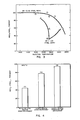
- Figure 1 is a graphical representation of data obtained using the process described by Lyon for NH3 and by Arand, et al. for urea.
- the data set forth in Figure 1 were obtained in a six-inch diameter refractory lined furnace where the primary combustion zone was fired with natural gas at a firing rate of 50,000 BTU/hour.
- the gas phase NO concentration prior to the injection of the reducing agent (“NO i ”) was 240 ppm.
- Ammonia was added in the form of a pure gas; the other compounds were added in the form of a dry powder mixed with an inert, limestone, to facilitate feeding.
- the nitrogen in the reducing agent was 1.5 times the molar nitrogen present as NO.
- the data are presented with the vertical axis showing the ratio of final NO (“(NO) f ”) to initial NO (“NO i ").
- the horizontal axis represents injection temperature of the nitrogen reducing agent into the refractory-lined furnace.
- SR stoichiometric ratio
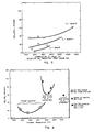
- Figure 2 illustrates results obtained with the two zone concept of this invention relative to ammonia injection using the existing art.
- the NH3 was injected at 1900°F (1040°C) and the temperature of the secondary air addition point was progressively decreased.
- Figure 3 shows the results of an analogous set of experiments to those shown in Figure 2. Again these experiments use the 50,000 BTU/hr. refractory-lined furnace but with urea injection.
- the solid symbols indicate the existing art with high temperature urea injection under fuel-rich conditions and medium temperature urea injection under fuel-lean conditions as described by Arand, et al.
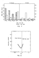
- Figure 3 is a graphical representation of data obtained using the process described by Perry et al. under combustion conditions. The data set forth in Figure 3 were obtained in a 6-inch diameter refractory-lined furnace where the primary combustion zone was fired with natural gas at a firing rate of 50,000 BTU/hour. The gas phase NO concentration prior to cyanuric acid injection (“(NO) i ”) was 600 ppm. The cyanuric acid was added in the form of a dry powder mixed with an inert limestone to facilitate feeding.
- NO gas phase NO concentration prior to cyanuric acid injection
- the data is presented with the vertical axis showing the ratio of final NO ((NO) f ) to initial NO ((NO) i ).
- the horizontal axis represents injection temperature of cyanuric acid into the refractory lined furnace.
- Figure 4 shows results which were obtained in a flow reactor substantially similar to that used by Perry except that the composition of the reactor wall could be changed as required. These data help explain the apparent disagreement between the results shown in Figure 1 and those reported by Perry.
- Figure 5 shows the results of an analogous set of experiments to those shown in Figure 3 using the two zone process of the present invention.
- the experiments which produced the data which are set forth in Figure 5 were conducted with the same facility and under the same experimental conditions as that shown in Figure 3.
- the same injection method is used, the same furnace was used, and the same natural gas firing rate was used.
- the nitrogen equivalent of the added cyanuric acid was 1.5 times the inlet NO.
- the temperature of the decomposition zone was varied by changing the location at which the cyanuric acid injection occurred.
- the temperature of the selective NO x reduction zone was varied by changing the location at which the final air was added in order to make the overall stoichiometry fuel lean.
- Table 1 shows the results of detailed species measurements made within the two zones and in the exhaust. These data indicate that the two zone process does not produce significant quantities of ammonia ("NH3") at any point in the process. This is probably because the likely key reactive intermediate is HNCO and not NH3.
- Figure 6 also shows data obtained with urea injection using the two zone concept of the present invention.
- the results using the present invention illustrate dramatically that significantly lower NO x levels can be achieved using the two zone concept with controlled stoichiometry than with either the fuel-lean or fuel-rich injection of the schemes of the existing art. Again, a far broader temperature window of acceptable performance exists for the process of the present invention as shown in Figure 6.
- Figure 7 summarizes the optimum results obtained with the two zone concept of the present invention. These data were again obtained in the six-inch diameter refractory-lined tunnel furnace with an initial NO concentration of 240 ppm.
- the selective reducing agent was injected at a rate to provide a molar equivalent nitrogen ratio of 1.5 times the inlet NO.
- the stoichiometry in the decomposition zone was maintained at 0.99 and the overall stoichiometry, after the addition of the final burn out air in the reaction zone was maintained at 1.02 for the two zone process (open bars).
- the shaded bars indicate the NO reduction achieved with fuel-lean injection according to the existing art.
- Figures 8 and 9 summarize the results of companion experiments designed to characterize the influence of local oxygen concentrations in both the decomposition zone and the reaction zone.
- Figure 8 illustrates the dependence of the selective NO x reduction zone on the stoichiometry in the cyanuric acid decomposition zone.
- Figure 9 shows the impact of oxygen concentration in the selective NO x reaction zone.
- Figure 10 shows the results of testing using an NO x control agent in conjunction with CaO in the slurry form.
- the data presented in Figure 10 clearly indicate that it is possible to achieve major reductions of both NO x and SO x emissions using the combined reagents of cyanuric acid and CaO.
- the reactivity of CaO with respect to SO2 is particularly surprising in view of previously reported literature on CaO injection which states that poor SO2 control is achieved with injection of commercial grade CaO (relative to injection of limestone or hydrated lime).
- the enhancement of performance appears to be directly related to the use of the slurry injection mechanism.
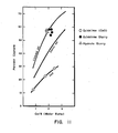
- Figure 11 shows the results of testing using various SO2 control concepts.
- the solid lines indicate typical performance by high and low efficiency atmospheric hydrates (Linwood and Colton respectively) and commercially produced lime (CaO).
- Figure 11 also shows data for a hydrate slurry (triangles) which resulted in essentially the same sulfur capture as was achieved with the hydrate alone. More importantly, however, Figure 11 illustrates data obtained with a quicklime slurry which indicate that very high capture levels can be achieved by simply slurrying commercial CaO and injecting the slurry under normal conditions at approximately 2300°F (1250°C). These data suggest that it is not necessary to externally hydrate the sorbent and dry it; the performance of the quicklime slurry is equivalent to that of the best commercial hydrate.
- a six-inch-diameter refractory-lined furnace was used and was fired by natural gas at a firing rate of 50,000 BTU/hour.
- the gas phase NO concentration prior to urea injection was about 240 ppm.
- Urea was injected into the furnace as a dry powder mixed with an inert substance (i.e. , limestone) to facilitate handling.
- the ratio of injected urea to NO in the combustion effluents was 1.5.
- the stoichiometric ratio within the furnace was approximately 1.25. That is, the furnace was operated so as to produce combustion effluents in which 25% excess O2 was present.
- Urea was injected in the absence of O2 at temperatures at about 2000°F (1100°C).
- Example 2 the same facility as set forth in Example 1 was used.
- the nitrogen equivalent in the added urea was again 1.5 times the inlet NO which was 240 ppm.
- the urea was injected into an oxygen deficient zone with an overall stoichiometry of 0.99.
- the bulk gas temperature at the point of injection was about 2450°F (1340°C).
- the urea was allowed to selectively react with the NO during a residence time of approximately 300 milliseconds ("ms") after which additional air was added to bring the overall stoichiometry up to 1.02.
- the temperature at which the final burnout air was added was approximately 2250°F (1230°C).
- Example 2 In this example the same facility as that set forth in Example 1 was used.
- the gas phase NO concentration prior to urea injection was about 240 ppm and the nitrogen equivalent in the added urea was about 1.5 times the inlet NO.
- the urea was decomposed in an oxygen deficient zone with an overall stoichiometry of 0.99.
- the reaction of the urea decomposition products and NO was allowed to occur subsequently in a downstream zone with an overall stoichiometry of 1.02.
- the temperature at the point of urea injection in the decomposition zone was approximately 1870°F (1020°C) and the temperature in the reaction zone after the addition of the final burnout air was about 1550°F (850°C).
- a six-inch diameter refractory-lined furnace was used and was fired by natural gas at a firing rate of 50,000 BTU/hour.
- the gas phase NO concentration prior to cyanuric acid injection was about 600 ppm.
- Cyanuric acid was injected into the furnace as a dry powder mixed with an inert substance (e.g. , limestone) to facilitate handling.
- the ratio of injected cyanuric acid to NO in the combustion effluents was 1.5.
- the stoichiometric ratio within the furnace was approximately 0.95. That is, the furnace was operated so as to produce combustion effluents in which O2 was deficient.
- Cyanuric acid was injected in the absence of O2 at temperatures at about 1900°F (1040°C).
- cyanuric acid was decomposed in an oxygen deficient zone with an overall stoichiometry of 0.99.
- the reaction of the cyanuric acid decomposition products and NO was allowed to occur subsequently in a downstream zone with an overall stoichiometry of 1.01.
- the temperature of the decomposition zone was held at about 1900°F (1040°C) and the temperature in the reaction zone was about 1900°F (1040°C).
- the concentration of NO x following the selective reaction zone was 115 ppm.
- Example 3 demonstrates that remarkably higher reduction efficiencies can be achieved using the two-zone process of the present invention.
- a flow reactor having stainless steel walls was employed.
- the nitrogen equivalent of added cyanuric acid was about 1.5 times the inlet NO.
- the only species in the reactor other than the NO and cyanuric acid reactants was argon.
- the initial concentration of NO was about 600 ppm and the reactor was maintained at a temperature of about 1200°F (650°C).
- Example 6 In this example the same conditions as those described in Example 6 were produced.
- the flow reactor was equipped with quartz walls. Under these conditions the NO concentration was reduced from 600 ppm to about 565 ppm.
- the overall stoichiometric ratio being 1.25, the temperature at the point of injection was approximately 2200°F (1200°C).
- CaO was injected into this zone in the form of a slurry with the Ca/S ratio being 2.0.
- the reactants were allowed to react in this zone for approximately 400 milliseconds.
- Example 3 the same facility and reaction conditions as set forth in Example 3 were used. In this example, however, ammonia gas was added instead of urea and the nitrogen equivalent in the ammonia was 1.5 times the inlet NO.
- the ammonia was decomposed in an oxygen deficient zone with an overall stoichiometry of 0.99.
- the reaction of the ammonia decomposition products and NO was allowed to occur subsequently in a downstream zone with an overall stoichiometry of 1.02.
- the temperature at the point of NH3 injection and decomposition was held at about 1900°F (1040°C) and the temperature at the beginning of the reaction zone where the final burnout air was added was about 1550°F (850°C).
- the concentration of NO following the selective reaction zone was 120 ppm corresponding to a 50% overall reduction.
- Example 14 the same facility and reaction conditions as set forth in Example 1 were used. Ammonium sulfate was added to provide the nitrogen equivalent of about 1.5 times the inlet NO.
- ammonium sulfate was added under excess air conditions at a temperature of approximately 2100°F (1150°C).
- the overall stoichiometry was 1.25 corresponding to 25% excess O2.
- the ammonium sulfate was allowed to decompose and selectively reduce the NO x , both under excess oxygen conditions.
- the concentration of NO x following the reaction was about 95 ppm.
- Example 15 the same facility and reaction conditions as set forth in Example 3 were used. Ammonium sulfate was added at a flow rate to provide the nitrogen equivalent of 1.5 times the inlet NO.
- ammonium sulfate was decomposed in an oxygen deficient zone with an overall stoichiometry of 0.99.
- the reaction of the ammonium sulfate decomposition products and NO was allowed to occur subsequently in a downstream zone with an overall stoichiometry of 1.02.
- the temperature at the point of ammonium sulfate injection in the decomposition zone was held at about 1870°F (1020°C) and the temperature at the beginning of the reaction zone where the final burnout air was added was about 1560°F (850°C).
- Example 16 the same facility and reaction conditions as set forth in Example 15 were used. Ammonium sulfate was added to provide a nitrogen equivalent of about 1.5 times the inlet NO.
- ammonium sulfate was added to an oxygen deficient zone with an overall stoichiometry of 0.99.
- both the ammonium sulfate and the final burnout air were added at a temperature of about 1850°F (1010°C).
- the final burnout air increased the overall stoichiometry to 1.02.
- the concentration of NO x in the exhaust was 35 ppm corresponding an overall reduction of approximately 85%.
- Data were obtained using a six-inch-diameter refractory-lined furnace where the primary combustion zone was fired with natural gas at a firing rate of 50,000 BTU/hr.
- the gas phase NO concentration in the primary zone was 80 ppm.
- Data are obtained using a six-inch-diameter refractory-lined furnace where the primary combustion zone is fired with natural gas at a firing rate of 50,000 BTU per hour.
- the gas phase NO concentration prior to cyanuric acid injection is 600 ppm and the SO2 concentration is 4000 ppm.
- An initial oxygen-free zone containing CO and H2O is maintained, the stoichiometric ratio being 0.99.
- the temperature in the first zone is maintained at approximately 1900°F (1040°C).
- Cyanuric acid is injected into this zone in the form of a solid. Cyanuric acid is allowed to react in this zone for approximately 0.3 seconds.
- the cyanuric acid decomposition products are added to a reaction zone having an excess of oxygen containing the NO x to be reduced.
- the stoichiometric ratio is 1.1.
- the temperature within the oxygen-rich environment is maintained at approximately 1600°F (870°C). Mixing between the cyanuric acid decomposition products and the combustion effluents in the second zone takes place for approximately 0.3 seconds.
- a CaO slurry is injected into the reaction zone combustion products at 2200°F (1200°C).
- the concentration of NO x is reduced from an initial concentration of 600 ppm to a final concentration of 30 ppm and the SO2 concentration is reduced from an initial concentration of 4000 ppm to 1300 ppm.
- Data are obtained using a 500 MW pulverized coal-fired boiler where the primary combustion zone is fired with a high sulfur midwestern bituminous coal.
- the primary zone in the lower furnace is fired under normal combustion conditions with excess oxygen corresponding to an overall stoichiometry of 1.05.
- Natural gas is injected above the primary combustion zone to reduce the overall stoichiometry to 0.97.
- a CaO slurry containing calcium equivalent to a Ca/SO2 ratio of 2.5 is injected at 2200°F (1200°C).
- the initial air fraction includes an ammonium sulfate solution with a nitrogen content equivalent to 2.0 times the NO x .
- This first airstream is injected at 1850°F (1010°C) and is at the flow rate required to increase the overall stoichiometry to 1.02. Approximately 100 ms later the final remaining burnout air is added to raise the overall stoichiometry to 1.2.
- the concentration of NO x is reduced from an uncontrolled concentration of 550 ppm to a final concentration of 40 ppm.
- the SO2 concentration is reduced from an initial concentration of 4000 ppm to 1500 ppm.
- Data are obtained using a large grate-fired incinerator which is charged with municipal solid waste at a rate of 1800 tons/day.
- the overall stoichiometry in the primary combustion zone corresponds to 1.5 (50% excess oxygen).
- Ammonium sulfate is decomposed in a separate chamber by passing fuel-rich combustion products from a separate natural gas fired flame through a bed of ammonium sulfate.
- the temperature of this bed is maintained at 1900°F (1040°C) and the nominal stoichiometry of the fuel-rich products is 0.99.
- the effluent from this decomposition zone is injected into the exhaust gas stream from the municipal waste incinerator at a temperature of 1600°F (870°C).
- the equivalent nitrogen flow rate in the ammonium sulfate decomposition products is maintained at 3.0 times the NO x flow from the incinerator.
- Data are obtained using a 350 cubic inch V8 engine where the engine is fueled with gasoline.
- the engine is tuned such that the stoichiometry in the combustion zone is 0.98.
- the combustion products flow from the engine at approximately 900°F (480°C) and enter a decomposition zone where urea is being decomposed by contacting with the oxygen deficient combustion products.
- Data are obtained using a 300-foot-long, 10-foot-diameter cement kiln being fired with low sulfur western bituminous coal.
- the gas phase NO concentration in the exhaust prior to the application of ammonium sulfate injection is 800 ppm.
- the coal fired primary zone is operated under normal conditions with 1.5% excess oxygen. Approximately 30 feet from the end of the kiln natural gas is added to reduce the overall stoichiometric ratio to 0.99. Approximately 15 feet from the end of the kiln at a temperature of 1000°F (540°C) ammonium sulfate is added with the final burnout air so that the overall exhaust oxygen concentration is 2.0%. The ammonium sulfate is fed at a rate sufficient to provide an equivalent nitrogen flow of 3.0 times the uncontrolled NO x emissions.
- NO x emissions can be reduced in excess of 90% with total NO x emissions being below 100 ppm.
- the present invention has potential for use in controlling emissions from numerous types of combustion emission sources including stationary boilers and the like, as well as motor vehicles.
- the present invention provides that -NH and -CN containing selective reducing agents are decomposed into certain decomposition products in an oxygen-free zone containing CO as the result of fuel-rich combustion processes.
- This zone is maintained at a temperature of from about 300°F to 3000°F (150°C to 1650°C).
- the decomposition products are introduced into a second reaction zone having an excess of oxygen. The temperature within this zone is maintained at between approximately 500°F (260°C) and approximately 2600°F (1425°C).
- SO x control can also be combined with control of NO x using this system. It is presently preferred to inject CaO in various forms along with cyanuric acid into the effluent stream. This results in good control of SO x .
Applications Claiming Priority (4)
| Application Number | Priority Date | Filing Date | Title |
|---|---|---|---|
| US39324 | 1987-04-16 | ||
| US07/039,324 US4861567A (en) | 1987-04-16 | 1987-04-16 | Methods of reducing NOx and SOx emissions from combustion systems |
| US07/073,980 US4851201A (en) | 1987-04-16 | 1987-07-15 | Methods of removing NOx and SOx emissions from combustion systems using nitrogenous compounds |
| US73980 | 1987-07-15 |
Publications (3)
| Publication Number | Publication Date |
|---|---|
| EP0287224A2 true EP0287224A2 (fr) | 1988-10-19 |
| EP0287224A3 EP0287224A3 (en) | 1990-12-12 |
| EP0287224B1 EP0287224B1 (fr) | 1995-11-29 |
Family
ID=26716018
Family Applications (1)
| Application Number | Title | Priority Date | Filing Date |
|---|---|---|---|
| EP88302535A Expired - Lifetime EP0287224B1 (fr) | 1987-04-16 | 1988-03-23 | Méthode d'élimination des émissions de NOx et de SOx des systèmes de combustion en utilisant des composants contenant de l'azote |
Country Status (4)
| Country | Link |
|---|---|
| US (1) | US4851201A (fr) |
| EP (1) | EP0287224B1 (fr) |
| AT (1) | ATE130780T1 (fr) |
| DE (1) | DE3854728T2 (fr) |
Cited By (19)
| Publication number | Priority date | Publication date | Assignee | Title |
|---|---|---|---|---|
| US4886650A (en) * | 1986-05-05 | 1989-12-12 | Robert Perry | No reduction using sublimation of cyanuric acid |
| US4908193A (en) * | 1986-05-05 | 1990-03-13 | Perry Robert A | No reduction using sublimation of cyanuric acid |
| GB2232972A (en) * | 1989-05-06 | 1991-01-02 | Hitachi Shipbuilding Eng Co | Removing nitrogen oxides and sulphur oxides from exhaust gas |
| EP0476201A1 (fr) * | 1990-09-17 | 1992-03-25 | Miriam S. Mozes | Procédé pour le contrôle d'émissions de gaz acides dans des gaz d'échappement d'une centrale thermique |
| WO1992004962A1 (fr) * | 1990-09-14 | 1992-04-02 | Cummins Power Generation, Inc. | PROCEDE ET APPAREIL SERVANT A ELIMINER DU NOx DANS DES FLUX DE GAZ |
| EP0524953A1 (fr) * | 1990-03-07 | 1993-02-03 | Fuel Tech Inc | Procede de reduction des oxydes d'azote sans formation d'oxyde azote. |
| EP0535313A3 (en) * | 1991-08-02 | 1993-08-11 | Eniricerche S.P.A. | Reduction of combustion effluent pollutants |
| EP0558809A1 (fr) * | 1992-02-27 | 1993-09-08 | Asea Brown Boveri Ag | Procédé pour la réduction des oxydes d'azote dans des gaz de fumée |
| US5518702A (en) * | 1986-05-05 | 1996-05-21 | Perry; Robert A. | No reduction using sublimination of cyanuric acid |
| EP0877649A1 (fr) * | 1996-01-11 | 1998-11-18 | Energy And Environmental Research Corporation | TECHNIQUES DE POINTE AMELIOREES DE REBRULAGE AUX FINS D'UNE REGULATION TRES EFFICACE DES EMISSIONS DE NO x? |
| EP0911072A2 (fr) * | 1997-10-23 | 1999-04-28 | Wülfrather Zement GmbH & Co.KG | Procédé et dispositif pour la réduction des émissions de NOx |
| WO1999030811A1 (fr) * | 1997-12-12 | 1999-06-24 | Fev Motorentechnik Gmbh & Co. Kommanditgesellschaft | Procede de reduction d'oxyde d'azote contenus dans des gaz d'evacuation contenant de l'oxygene, en particulier dans des gaz d'echappement de moteurs a combustion interne |
| EP0946254A1 (fr) * | 1996-11-01 | 1999-10-06 | Noxtech, Inc. | PROCEDE DE REDUCTION DES NOx PROVENANT DES GAZ DE DEGAGEMENT DES PROCESSUS INDUSTRIELS |
| EP1421028A2 (fr) * | 2001-08-08 | 2004-05-26 | Cement Industry Environmental Consortium | Introduction de dechets de cyanure comme reducteurs des nox |
| WO2005060670A2 (fr) * | 2003-12-20 | 2005-07-07 | Higgins Brian S | Procede permettant de reduire les emissions produites par la de combustion de nox |
| US7537743B2 (en) | 2004-02-14 | 2009-05-26 | Mobotec Usa, Inc. | Method for in-furnace regulation of SO3 in catalytic NOx reducing systems |
| US7670569B2 (en) | 2003-06-13 | 2010-03-02 | Mobotec Usa, Inc. | Combustion furnace humidification devices, systems & methods |
| US8251694B2 (en) | 2004-02-14 | 2012-08-28 | Nalco Mobotec, Inc. | Method for in-furnace reduction flue gas acidity |
| CN106000072A (zh) * | 2016-06-29 | 2016-10-12 | 青岛惠城环保科技股份有限公司 | 一种降低fcc再生烟气中nox排放的方法 |
Families Citing this family (31)
| Publication number | Priority date | Publication date | Assignee | Title |
|---|---|---|---|---|
| US4996036A (en) * | 1988-12-28 | 1991-02-26 | Allied-Signal Inc. | Abatement of NOx from hydroxylamine disulfonate process |
| US5058514A (en) * | 1989-10-18 | 1991-10-22 | Mozes Miriam S | Process for controlling acid gas emissions in power plant flue gases |
| US5165903A (en) * | 1990-04-16 | 1992-11-24 | Public Service Company Of Colorado | Integrated process and apparatus for control of pollutants in coal-fired boilers |
| US5543123A (en) * | 1990-08-01 | 1996-08-06 | Nalco Fuel Tech | Low pressure formation of a urea hydrolysate for nitrogen oxides reduction |
| US5078982A (en) * | 1990-09-20 | 1992-01-07 | Molecular Technology Corporation | Reduction of nitrogen oxide in effluent gases using formaldehyde |
| US5192515A (en) * | 1990-09-20 | 1993-03-09 | Molecular Technology Corporation | Reduction of nitrogen oxide and carbon monoxide in effluent gases |
| US5234670A (en) * | 1990-09-20 | 1993-08-10 | Molecular Technology Corporation | Reduction of nitrogen oxide in effluent gases using NCO radicals |
| US5171558A (en) * | 1990-09-20 | 1992-12-15 | Molecular Technology Corporation | Catalytic decomposition of cyanuric acid and use of product to reduce nitrogen oxide emissions |
| US5234671A (en) * | 1990-09-20 | 1993-08-10 | Molecular Technology Corporation | Reduction of nitrogen oxide in effluent gases using formaldehyde and/or formaldehyde-derived free radicals |
| US5171554A (en) * | 1990-09-20 | 1992-12-15 | Molecular Technology Corporation | Conversion of formaldehyde and nitrogen to a gaseous product and use of gaseous product in reduction of nitrogen oxide in effluent gases |
| US5087431A (en) * | 1990-09-20 | 1992-02-11 | Molecular Technology Corporation | Catalytic decomposition of cyanuric acid and use of product to reduce nitrogen oxide emissions |
| US5139755A (en) * | 1990-10-17 | 1992-08-18 | Energy And Environmental Research Corporation | Advanced reburning for reduction of NOx emissions in combustion systems |
| US5118481A (en) * | 1990-11-09 | 1992-06-02 | Energy And Environmental Research Corporation | Methods for reducing NOx emissions from combustion effluents |
| US5270025A (en) * | 1991-04-05 | 1993-12-14 | Energy & Environmental Research Corp. | Methods for controlling N2 O emissions and for the reduction of NO.sub.x emissions in combustion systems while controlling N2 O emissions |
| US5252058A (en) * | 1991-06-25 | 1993-10-12 | Fulton Thermatec Corporation | Method and apparatus for recirculating flue gas in a pulse combustor |
| US5145354A (en) * | 1991-06-25 | 1992-09-08 | Fulton Thermatec Corporation | Method and apparatus for recirculating flue gas in a pulse combustor |
| WO1993003998A1 (fr) * | 1991-08-26 | 1993-03-04 | Cummins Power Generation, Inc. | PROCEDE ET APPAREIL POUR ELIMINER LE NOx DES GAZ D'ECHAPPEMENT AU MOYEN D'ACIDE CYANURIQUE |
| US5263850A (en) * | 1992-02-05 | 1993-11-23 | Boston Thermal Energy Corporation | Emission control system for an oil-fired combustion process |
| US5279108A (en) * | 1992-02-28 | 1994-01-18 | Union Oil Company Of California | System for reduction of NOx in jet engine exhaust |
| US6258336B1 (en) | 1995-06-09 | 2001-07-10 | Gas Research Institute | Method and apparatus for NOx reduction in flue gases |
| US5967061A (en) * | 1997-01-14 | 1999-10-19 | Energy And Environmental Research Corporation | Method and system for reducing nitrogen oxide and sulfur oxide emissions from carbonaceous fuel combustion flue gases |
| US5988081A (en) * | 1997-07-22 | 1999-11-23 | Energy & Environmental Research Corporation | Method and system for the disposal of coal preparation plant waste coal through slurry co-firing in cyclone-fired boilers to effect a reduction in nitrogen oxide emissions |
| US6858540B2 (en) * | 2000-05-11 | 2005-02-22 | Applied Materials, Inc. | Selective removal of tantalum-containing barrier layer during metal CMP |
| US6280695B1 (en) | 2000-07-10 | 2001-08-28 | Ge Energy & Environmental Research Corp. | Method of reducing NOx in a combustion flue gas |
| US6436359B1 (en) | 2000-10-25 | 2002-08-20 | Ec&C Technologies, Inc. | Method for controlling the production of ammonia from urea for NOx scrubbing |
| US7168947B2 (en) * | 2004-07-06 | 2007-01-30 | General Electric Company | Methods and systems for operating combustion systems |
| US7410356B2 (en) | 2005-11-17 | 2008-08-12 | Mobotec Usa, Inc. | Circulating fluidized bed boiler having improved reactant utilization |
| US20090148370A1 (en) * | 2007-12-06 | 2009-06-11 | Spencer Iii Herbert W | Process to produce ammonia from urea |
| US8069824B2 (en) | 2008-06-19 | 2011-12-06 | Nalco Mobotec, Inc. | Circulating fluidized bed boiler and method of operation |
| US9586831B2 (en) | 2014-06-09 | 2017-03-07 | Wahlco, Inc. | Urea to ammonia process |
| RU2701014C1 (ru) * | 2017-04-26 | 2019-09-24 | Евгений Михайлович Герасимов | Способ термического обезвреживания газов продувки скважин, выходящих из бурения на месторождениях сернистых газов |
Citations (4)
| Publication number | Priority date | Publication date | Assignee | Title |
|---|---|---|---|---|
| GB1488087A (en) * | 1975-03-04 | 1977-10-05 | Zink Co John | Process for disposal of oxides of nitrogen |
| US4335084A (en) * | 1980-01-24 | 1982-06-15 | Roldiva, Inc. | Method for reducing NOx emissions from combustion processes |
| DE3447616A1 (de) * | 1983-12-30 | 1985-07-11 | Skw Trostberg Ag, 8223 Trostberg | Mittel und verfahren zur gleichzeitigen entfernung von schwefel- und stickoxiden aus abgasen |
| WO1987006923A1 (fr) * | 1986-05-05 | 1987-11-19 | Perry Robert A | Reduction de no par sublimation d'acide cyanurique |
Family Cites Families (17)
| Publication number | Priority date | Publication date | Assignee | Title |
|---|---|---|---|---|
| US3382822A (en) * | 1967-02-24 | 1968-05-14 | Interior Usa | Method of burning coal |
| US3746498A (en) * | 1972-01-24 | 1973-07-17 | Combustion Eng | Reducing no{11 {11 emissions by additive injection |
| US3900554A (en) * | 1973-03-16 | 1975-08-19 | Exxon Research Engineering Co | Method for the reduction of the concentration of no in combustion effluents using ammonia |
| JPS51137670A (en) * | 1975-05-26 | 1976-11-27 | Asahi Chem Ind Co Ltd | Method for decreasing nitrogen oxides in exhaust gas |
| US4041699A (en) * | 1975-12-29 | 1977-08-16 | The Garrett Corporation | High temperature gas turbine |
| JPS5291776A (en) * | 1976-01-30 | 1977-08-02 | Mitsubishi Heavy Ind Ltd | Treatment of nitrogen oxides in exhaust gas |
| US4208386A (en) * | 1976-03-03 | 1980-06-17 | Electric Power Research Institute, Inc. | Urea reduction of NOx in combustion effluents |
| JPS5318466A (en) * | 1976-08-05 | 1978-02-20 | Mitsubishi Heavy Ind Ltd | Charging method for oxygen-containing hydrocarbons and/or their precursors into exhaust gas |
| JPS53128023A (en) * | 1977-04-15 | 1978-11-08 | Toray Ind Inc | Method for reducing the concentration of nitrogen oxide in combustion effluent gas |
| JPS5428771A (en) * | 1977-08-08 | 1979-03-03 | Asahi Fibreglass Co | Waste gas treatment |
| US4325924A (en) * | 1977-10-25 | 1982-04-20 | Electric Power Research Institute, Inc. | Urea reduction of NOx in fuel rich combustion effluents |
| US4395223A (en) * | 1978-06-09 | 1983-07-26 | Hitachi Shipbuilding & Engineering Co., Ltd. | Multi-stage combustion method for inhibiting formation of nitrogen oxides |
| US4368057A (en) * | 1980-10-14 | 1983-01-11 | Matthews Ronald D | Method for reducing ammonia concentration in pre-combusted fuel gas using nitric oxide |
| DE3428231A1 (de) * | 1983-12-16 | 1985-07-04 | Süd-Chemie AG, 8000 München | Verfahren zur entfernung von stickoxiden aus abgasen |
| US4719092A (en) * | 1985-10-04 | 1988-01-12 | Fuel Tech, Inc. | Reduction of nitrogen-based pollutants through the use of urea solutions containing oxygenated hydrocarbon solvents |
| US4645652A (en) * | 1985-11-29 | 1987-02-24 | General Electric Company | Method for scrubbing sulfur oxides and nitrogen oxides in a flue gas duct |
| US4731233A (en) * | 1986-01-09 | 1988-03-15 | Thompson Richard E | Method and composition for utilizing lime-urea hydrates to simultaneously reduce NOx and SOx in combustion effluents |
-
1987
- 1987-07-15 US US07/073,980 patent/US4851201A/en not_active Expired - Fee Related
-
1988
- 1988-03-23 EP EP88302535A patent/EP0287224B1/fr not_active Expired - Lifetime
- 1988-03-23 AT AT88302535T patent/ATE130780T1/de active
- 1988-03-23 DE DE3854728T patent/DE3854728T2/de not_active Expired - Fee Related
Patent Citations (4)
| Publication number | Priority date | Publication date | Assignee | Title |
|---|---|---|---|---|
| GB1488087A (en) * | 1975-03-04 | 1977-10-05 | Zink Co John | Process for disposal of oxides of nitrogen |
| US4335084A (en) * | 1980-01-24 | 1982-06-15 | Roldiva, Inc. | Method for reducing NOx emissions from combustion processes |
| DE3447616A1 (de) * | 1983-12-30 | 1985-07-11 | Skw Trostberg Ag, 8223 Trostberg | Mittel und verfahren zur gleichzeitigen entfernung von schwefel- und stickoxiden aus abgasen |
| WO1987006923A1 (fr) * | 1986-05-05 | 1987-11-19 | Perry Robert A | Reduction de no par sublimation d'acide cyanurique |
Cited By (30)
| Publication number | Priority date | Publication date | Assignee | Title |
|---|---|---|---|---|
| US5518702A (en) * | 1986-05-05 | 1996-05-21 | Perry; Robert A. | No reduction using sublimination of cyanuric acid |
| US4908193A (en) * | 1986-05-05 | 1990-03-13 | Perry Robert A | No reduction using sublimation of cyanuric acid |
| US4886650A (en) * | 1986-05-05 | 1989-12-12 | Robert Perry | No reduction using sublimation of cyanuric acid |
| GB2232972A (en) * | 1989-05-06 | 1991-01-02 | Hitachi Shipbuilding Eng Co | Removing nitrogen oxides and sulphur oxides from exhaust gas |
| GB2232972B (en) * | 1989-05-06 | 1993-09-15 | Hitachi Shipbuilding Eng Co | Treatment of combustion exhaust gas |
| EP0524953A1 (fr) * | 1990-03-07 | 1993-02-03 | Fuel Tech Inc | Procede de reduction des oxydes d'azote sans formation d'oxyde azote. |
| EP0524953A4 (en) * | 1990-03-07 | 1993-04-07 | Fuel Tech, Inc. | Process for reducing nitrogen oxides without generating nitrous oxide |
| WO1992004962A1 (fr) * | 1990-09-14 | 1992-04-02 | Cummins Power Generation, Inc. | PROCEDE ET APPAREIL SERVANT A ELIMINER DU NOx DANS DES FLUX DE GAZ |
| AU659413B2 (en) * | 1990-09-14 | 1995-05-18 | Cummins Power Generation, Inc. | Process and apparatus for removing NOx from gas streams |
| EP0476201A1 (fr) * | 1990-09-17 | 1992-03-25 | Miriam S. Mozes | Procédé pour le contrôle d'émissions de gaz acides dans des gaz d'échappement d'une centrale thermique |
| EP0535313A3 (en) * | 1991-08-02 | 1993-08-11 | Eniricerche S.P.A. | Reduction of combustion effluent pollutants |
| EP0558809A1 (fr) * | 1992-02-27 | 1993-09-08 | Asea Brown Boveri Ag | Procédé pour la réduction des oxydes d'azote dans des gaz de fumée |
| EP0877649A1 (fr) * | 1996-01-11 | 1998-11-18 | Energy And Environmental Research Corporation | TECHNIQUES DE POINTE AMELIOREES DE REBRULAGE AUX FINS D'UNE REGULATION TRES EFFICACE DES EMISSIONS DE NO x? |
| EP0877649A4 (fr) * | 1996-01-11 | 1999-10-27 | Energy & Environ Res Corp | TECHNIQUES DE POINTE AMELIOREES DE REBRULAGE AUX FINS D'UNE REGULATION TRES EFFICACE DES EMISSIONS DE NO x? |
| EP1949952A3 (fr) * | 1996-11-01 | 2008-08-13 | Noxtech, Inc. | Procédé de réduction de NOx de gaz d'échappement produits par des processus industriels |
| EP0946254A4 (fr) * | 1996-11-01 | 2001-07-25 | Noxtech Inc | PROCEDE DE REDUCTION DES NOx PROVENANT DES GAZ DE DEGAGEMENT DES PROCESSUS INDUSTRIELS |
| EP0946254A1 (fr) * | 1996-11-01 | 1999-10-06 | Noxtech, Inc. | PROCEDE DE REDUCTION DES NOx PROVENANT DES GAZ DE DEGAGEMENT DES PROCESSUS INDUSTRIELS |
| EP0911072A3 (fr) * | 1997-10-23 | 1999-06-23 | Wülfrather Zement GmbH & Co.KG | Procédé et dispositif pour la réduction des émissions de NOx |
| EP0911072A2 (fr) * | 1997-10-23 | 1999-04-28 | Wülfrather Zement GmbH & Co.KG | Procédé et dispositif pour la réduction des émissions de NOx |
| WO1999030811A1 (fr) * | 1997-12-12 | 1999-06-24 | Fev Motorentechnik Gmbh & Co. Kommanditgesellschaft | Procede de reduction d'oxyde d'azote contenus dans des gaz d'evacuation contenant de l'oxygene, en particulier dans des gaz d'echappement de moteurs a combustion interne |
| EP1421028A2 (fr) * | 2001-08-08 | 2004-05-26 | Cement Industry Environmental Consortium | Introduction de dechets de cyanure comme reducteurs des nox |
| EP1421028A4 (fr) * | 2001-08-08 | 2006-06-07 | Cement Industry Environmental | Introduction de dechets de cyanure comme reducteurs des nox |
| US7335014B2 (en) * | 2003-06-12 | 2008-02-26 | Mobotec Usa, Inc. | Combustion NOx reduction method |
| US7670569B2 (en) | 2003-06-13 | 2010-03-02 | Mobotec Usa, Inc. | Combustion furnace humidification devices, systems & methods |
| US8021635B2 (en) | 2003-06-13 | 2011-09-20 | Nalco Mobotec, Inc. | Combustion furnace humidification devices, systems and methods |
| WO2005060670A2 (fr) * | 2003-12-20 | 2005-07-07 | Higgins Brian S | Procede permettant de reduire les emissions produites par la de combustion de nox |
| WO2005060670A3 (fr) * | 2003-12-20 | 2006-04-20 | Brian S Higgins | Procede permettant de reduire les emissions produites par la de combustion de nox |
| US7537743B2 (en) | 2004-02-14 | 2009-05-26 | Mobotec Usa, Inc. | Method for in-furnace regulation of SO3 in catalytic NOx reducing systems |
| US8251694B2 (en) | 2004-02-14 | 2012-08-28 | Nalco Mobotec, Inc. | Method for in-furnace reduction flue gas acidity |
| CN106000072A (zh) * | 2016-06-29 | 2016-10-12 | 青岛惠城环保科技股份有限公司 | 一种降低fcc再生烟气中nox排放的方法 |
Also Published As
| Publication number | Publication date |
|---|---|
| DE3854728D1 (de) | 1996-01-11 |
| DE3854728T2 (de) | 1996-10-10 |
| ATE130780T1 (de) | 1995-12-15 |
| EP0287224A3 (en) | 1990-12-12 |
| US4851201A (en) | 1989-07-25 |
| EP0287224B1 (fr) | 1995-11-29 |
Similar Documents
| Publication | Publication Date | Title |
|---|---|---|
| EP0287224B1 (fr) | Méthode d'élimination des émissions de NOx et de SOx des systèmes de combustion en utilisant des composants contenant de l'azote | |
| US4861567A (en) | Methods of reducing NOx and SOx emissions from combustion systems | |
| EP0495089B1 (fr) | Reduction d'oxydes d'azote par utilisation d'un hydrolysat d'uree | |
| EP0242394B1 (fr) | Diminution des polluants a base d'azote par l'emploi de solution d'uree contenant des solvants d'hydrocarbure oxygene | |
| EP2440756B1 (fr) | TRAITEMENT DES NOx PRESENTS DANS LES GAZ DE CARNEAU | |
| EP0877649B1 (fr) | TECHNIQUES DE POINTE AMELIOREES DE REBRULAGE AUX FINS D'UNE REGULATION TRES EFFICACE DES EMISSIONS DE NOx | |
| US3900554A (en) | Method for the reduction of the concentration of no in combustion effluents using ammonia | |
| US5670122A (en) | Methods for removing air pollutants from combustion flue gas | |
| US9114357B2 (en) | Treatment of nitrogen oxides in flue gas streams | |
| US5543123A (en) | Low pressure formation of a urea hydrolysate for nitrogen oxides reduction | |
| WO2001015796A1 (fr) | PROCEDES A LIMITER NOx DANS DES GAZ DE COMBUSTION AU MOYEN D'ADDITIFS CONTENANT DES METAUX | |
| WO1993019006A1 (fr) | PROCEDE DE REGULATION DES EMISSIONS DE N2O ET DE REDUCTION DES EMISSIONS DE NOx ET DE SOx DANS DES SYSTEMES DE COMBUSTION | |
| US5087431A (en) | Catalytic decomposition of cyanuric acid and use of product to reduce nitrogen oxide emissions | |
| KR20040026653A (ko) | 암모니아 함유 배출 가스의 처리 방법 | |
| Grove et al. | NOx abatement system: using molecular sieve catalyst modules for a glass melting furnace | |
| Yeh et al. | Control of NO x During Stationary Combustion | |
| Yeh et al. | Control of NO | |
| EP0535313A2 (fr) | Réduction des effluents polluants de combustion | |
| WO1994009896A1 (fr) | Procede et composition de reduction de n2o par un agent de sorption | |
| Levendis | Control of coal combustion SO {sub 2} and NO {sub x} emissions by in-boiler injection of CMA. Final project report, July 1, 1992--December 31, 1994 | |
| EP0314842A1 (fr) | Méthode et composition pour l'utilisation des hydrates de chaux-urée pour réduire simultanément NOx et SOx dans des effluents de combustion | |
| WO1988007497A1 (fr) | Procede de reduction d'oxydes d'azote dans un effluent, utilisant un carbure d'hydrogene heterocyclique |
Legal Events
| Date | Code | Title | Description |
|---|---|---|---|
| PUAI | Public reference made under article 153(3) epc to a published international application that has entered the european phase |
Free format text: ORIGINAL CODE: 0009012 |
|
| AK | Designated contracting states |
Kind code of ref document: A2 Designated state(s): AT BE CH DE ES FR GB GR IT LI LU NL SE |
|
| PUAL | Search report despatched |
Free format text: ORIGINAL CODE: 0009013 |
|
| AK | Designated contracting states |
Kind code of ref document: A3 Designated state(s): AT BE CH DE ES FR GB GR IT LI LU NL SE |
|
| 17P | Request for examination filed |
Effective date: 19910531 |
|
| 17Q | First examination report despatched |
Effective date: 19911106 |
|
| GRAA | (expected) grant |
Free format text: ORIGINAL CODE: 0009210 |
|
| AK | Designated contracting states |
Kind code of ref document: B1 Designated state(s): AT BE CH DE ES FR GB GR IT LI LU NL SE |
|
| PG25 | Lapsed in a contracting state [announced via postgrant information from national office to epo] |
Ref country code: IT Free format text: LAPSE BECAUSE OF FAILURE TO SUBMIT A TRANSLATION OF THE DESCRIPTION OR TO PAY THE FEE WITHIN THE PRE;WARNING: LAPSES OF ITALIAN PATENTS WITH EFFECTIVE DATE BEFORE 2007 MAY HAVE OCCURRED AT ANY TIME BEFORE 2007. THE CORRECT EFFECTIVE DATE MAY BE DIFFERENT FROM THE ONE RECORDED.SCRIBED TIME-LIMIT Effective date: 19951129 Ref country code: GR Free format text: LAPSE BECAUSE OF FAILURE TO SUBMIT A TRANSLATION OF THE DESCRIPTION OR TO PAY THE FEE WITHIN THE PRESCRIBED TIME-LIMIT Effective date: 19951129 Ref country code: ES Free format text: THE PATENT HAS BEEN ANNULLED BY A DECISION OF A NATIONAL AUTHORITY Effective date: 19951129 Ref country code: LI Effective date: 19951129 Ref country code: NL Free format text: LAPSE BECAUSE OF FAILURE TO SUBMIT A TRANSLATION OF THE DESCRIPTION OR TO PAY THE FEE WITHIN THE PRESCRIBED TIME-LIMIT Effective date: 19951129 Ref country code: CH Effective date: 19951129 Ref country code: AT Effective date: 19951129 Ref country code: BE Effective date: 19951129 |
|
| REF | Corresponds to: |
Ref document number: 130780 Country of ref document: AT Date of ref document: 19951215 Kind code of ref document: T |
|
| REF | Corresponds to: |
Ref document number: 3854728 Country of ref document: DE Date of ref document: 19960111 |
|
| PG25 | Lapsed in a contracting state [announced via postgrant information from national office to epo] |
Ref country code: SE Effective date: 19960229 |
|
| PG25 | Lapsed in a contracting state [announced via postgrant information from national office to epo] |
Ref country code: LU Free format text: LAPSE BECAUSE OF NON-PAYMENT OF DUE FEES Effective date: 19960331 |
|
| ET | Fr: translation filed | ||
| NLV1 | Nl: lapsed or annulled due to failure to fulfill the requirements of art. 29p and 29m of the patents act | ||
| REG | Reference to a national code |
Ref country code: CH Ref legal event code: PL |
|
| PLBE | No opposition filed within time limit |
Free format text: ORIGINAL CODE: 0009261 |
|
| STAA | Information on the status of an ep patent application or granted ep patent |
Free format text: STATUS: NO OPPOSITION FILED WITHIN TIME LIMIT |
|
| 26N | No opposition filed | ||
| REG | Reference to a national code |
Ref country code: GB Ref legal event code: IF02 |
|
| PGFP | Annual fee paid to national office [announced via postgrant information from national office to epo] |
Ref country code: GB Payment date: 20050316 Year of fee payment: 18 |
|
| PGFP | Annual fee paid to national office [announced via postgrant information from national office to epo] |
Ref country code: FR Payment date: 20050321 Year of fee payment: 18 |
|
| PGFP | Annual fee paid to national office [announced via postgrant information from national office to epo] |
Ref country code: DE Payment date: 20050502 Year of fee payment: 18 |
|
| PG25 | Lapsed in a contracting state [announced via postgrant information from national office to epo] |
Ref country code: GB Free format text: LAPSE BECAUSE OF NON-PAYMENT OF DUE FEES Effective date: 20060323 |
|
| PG25 | Lapsed in a contracting state [announced via postgrant information from national office to epo] |
Ref country code: DE Free format text: LAPSE BECAUSE OF NON-PAYMENT OF DUE FEES Effective date: 20061003 |
|
| GBPC | Gb: european patent ceased through non-payment of renewal fee |
Effective date: 20060323 |
|
| REG | Reference to a national code |
Ref country code: FR Ref legal event code: ST Effective date: 20061130 |
|
| PG25 | Lapsed in a contracting state [announced via postgrant information from national office to epo] |
Ref country code: FR Free format text: LAPSE BECAUSE OF NON-PAYMENT OF DUE FEES Effective date: 20060331 |