EP0323334A1 - Apparatus for the safe attachment of an infant's vehicle seat to the rear seat of an automotive vehicle - Google Patents
Apparatus for the safe attachment of an infant's vehicle seat to the rear seat of an automotive vehicle Download PDFInfo
- Publication number
- EP0323334A1 EP0323334A1 EP88403307A EP88403307A EP0323334A1 EP 0323334 A1 EP0323334 A1 EP 0323334A1 EP 88403307 A EP88403307 A EP 88403307A EP 88403307 A EP88403307 A EP 88403307A EP 0323334 A1 EP0323334 A1 EP 0323334A1
- Authority
- EP
- European Patent Office
- Prior art keywords
- seat
- base
- belt
- vehicle
- clamp
- Prior art date
- Legal status (The legal status is an assumption and is not a legal conclusion. Google has not performed a legal analysis and makes no representation as to the accuracy of the status listed.)
- Granted
Links
- 230000003187 abdominal effect Effects 0.000 claims description 6
- 230000001174 ascending effect Effects 0.000 description 4
- 239000002184 metal Substances 0.000 description 4
- 210000003323 beak Anatomy 0.000 description 2
- 230000000694 effects Effects 0.000 description 2
- 239000002991 molded plastic Substances 0.000 description 2
- 238000000465 moulding Methods 0.000 description 2
- 238000005452 bending Methods 0.000 description 1
- 239000011093 chipboard Substances 0.000 description 1
- 239000011248 coating agent Substances 0.000 description 1
- 238000000576 coating method Methods 0.000 description 1
- 238000009434 installation Methods 0.000 description 1
- 230000003472 neutralizing effect Effects 0.000 description 1
- 108090000623 proteins and genes Proteins 0.000 description 1
- 239000002990 reinforced plastic Substances 0.000 description 1
- 230000002040 relaxant effect Effects 0.000 description 1
Images

Classifications
-
- B—PERFORMING OPERATIONS; TRANSPORTING
- B60—VEHICLES IN GENERAL
- B60N—SEATS SPECIALLY ADAPTED FOR VEHICLES; VEHICLE PASSENGER ACCOMMODATION NOT OTHERWISE PROVIDED FOR
- B60N2/00—Seats specially adapted for vehicles; Arrangement or mounting of seats in vehicles
- B60N2/24—Seats specially adapted for vehicles; Arrangement or mounting of seats in vehicles for particular purposes or particular vehicles
- B60N2/26—Seats specially adapted for vehicles; Arrangement or mounting of seats in vehicles for particular purposes or particular vehicles for children
- B60N2/28—Seats readily mountable on, and dismountable from, existing seats or other parts of the vehicle
- B60N2/2857—Seats readily mountable on, and dismountable from, existing seats or other parts of the vehicle characterised by the peculiar orientation of the child
- B60N2/286—Seats readily mountable on, and dismountable from, existing seats or other parts of the vehicle characterised by the peculiar orientation of the child forward facing
-
- B—PERFORMING OPERATIONS; TRANSPORTING
- B60—VEHICLES IN GENERAL
- B60N—SEATS SPECIALLY ADAPTED FOR VEHICLES; VEHICLE PASSENGER ACCOMMODATION NOT OTHERWISE PROVIDED FOR
- B60N2/00—Seats specially adapted for vehicles; Arrangement or mounting of seats in vehicles
- B60N2/24—Seats specially adapted for vehicles; Arrangement or mounting of seats in vehicles for particular purposes or particular vehicles
- B60N2/26—Seats specially adapted for vehicles; Arrangement or mounting of seats in vehicles for particular purposes or particular vehicles for children
- B60N2/28—Seats readily mountable on, and dismountable from, existing seats or other parts of the vehicle
- B60N2/2803—Adaptations for seat belts
- B60N2/2806—Adaptations for seat belts for securing the child seat to the vehicle
-
- B—PERFORMING OPERATIONS; TRANSPORTING
- B60—VEHICLES IN GENERAL
- B60N—SEATS SPECIALLY ADAPTED FOR VEHICLES; VEHICLE PASSENGER ACCOMMODATION NOT OTHERWISE PROVIDED FOR
- B60N2/00—Seats specially adapted for vehicles; Arrangement or mounting of seats in vehicles
- B60N2/24—Seats specially adapted for vehicles; Arrangement or mounting of seats in vehicles for particular purposes or particular vehicles
- B60N2/26—Seats specially adapted for vehicles; Arrangement or mounting of seats in vehicles for particular purposes or particular vehicles for children
- B60N2/28—Seats readily mountable on, and dismountable from, existing seats or other parts of the vehicle
- B60N2/2821—Seats readily mountable on, and dismountable from, existing seats or other parts of the vehicle having a seat and a base part
Definitions
- the present invention relates to a device for the safety attachment of a child car seat on a rear seat of a motor vehicle.
- the seat comprises a shell forming a body with a support base partially shaped at least in V, the substantially horizontal branch of which is intended to rest on the seat of the bench, while the substantially vertical branch of this base and the back of the shell are applied against the back of the bench.
- the safety device notably comprises two straps fixed at said points and whose free ends are engaged to allow their length adjustment, in double loops forming one body with lugs with eyelets.
- This known device requires the permanent fixing of special straps, which prevents the installation of seat belts on the rear seat when the latter was exempt on delivery of the vehicle. In any case, it can no longer be installed now, since the vehicles are delivered with seat belts at the rear. For old vehicles, the assembly of this child car seat is relatively long and inconvenient. In addition, the attachment does not prevent the seat from tilting forward by pivoting around the axis of the straps.
- Another known device takes advantage of the seat belt of the rear seat of the vehicle located on the chosen side.
- the lap belt and the shoulder belt strap, these straps being self-locking reel, cross the aforementioned passage formed between the shell and the base, such that when the bolt sliding on the belt at the limit of the two straps is locked in the loop attached to the vehicle, these straps are supported respectively on the substantially horizontal part of the base and against the top of the edge of the substantially vertical part of said base opposite said loop and near the hull.
- the tilting forward is prevented.
- this other known device has the drawback of great lateral mobility.
- cornering the child seat moves on the seat, which gives parents an impression of insecurity, the child a feeling of instability and the neighboring passenger a sensitive gene.
- the seat tends to return towards the middle of a rear seat and it is therefore not possible to choose the exact location of this seat.
- the harness strap cooperates with a reel, it can be unwound under the effect of low stresses, that is to say much less than those resulting from an impact and for which the reel is blocked. Due to this possible unwinding, the aforementioned lateral mobility is accentuated and can be accompanied by localized lifting when the child moves.
- a removable and captive double loop is provided; it makes it possible to bring together, near the bolt, the two straps which then pass through two lumens of a double pass by extending in a sinuous fashion on a median bar separating said lumens and on elements of extreme bars between which are formed passages for mounting and dismounting said loop on said straps; moreover, the passer-by is made captive by means of a flexible link attached to the seat.
- This passer-by has the drawback of being awkward to lay and wasting time; moreover, it hangs relative to the seat, which is a nuisance when handling the seat.
- the object of the present invention is to oppose any lateral mobility of the child seat and to fix this seat in any position on the seat at the will of the person who installs it. It is concomitantly intended to prevent the child seat from lifting slightly from the seat when the shoulder belt tends to unwind under the effect of low stress.
- the device of the invention cooperates, like the second aforementioned known device, with a vehicle seat belt and, in accordance with the invention, an opening clamp is mounted on the base to take the lap belt and lock it after correct lateral positioning of the seat on the bench.
- the clamp is fixed in an adjustable manner along a lower rear cross member of the base, in order to adapt to the different configurations of vehicle belts.
- US Patent No. 3,922,035 describes a child seat, a lower rear crossmember of its base is provided with a clamp system for attaching a lap belt in two pieces of a belt. These two pieces are themselves fixed to the attachment points of the floor of the motor vehicle, but without a self-locking reel. As soon as the strap cannot relax, the child seat is and remains perfectly stationary.
- US Patent No. 4,591,208 describes a child seat whose armrests are connected by a support bridge.
- the lap belt passes over this bridge and once tightened is fixed by means of a clamp system mounted on said bridge. Since the ends of the strap are themselves fixed to the attachment points of the floor of the motor vehicle without the intermediary of a self-locking reel, the child seat is and remains perfectly stationary.
- French Patent No. 2,602,409 describes a child seat frame which is held in place on the seat of a motor vehicle by the abdominal strap and the strap shoulder belt harness for this bench seat. These straps are fixed to the attachment points of the floor of this vehicle without the assistance of a self-locking reel. As soon as the shoulder belt is fixed on the upper rear crossmember of the frame, the child seat is positioned at the top but its base can move laterally.
- a second clamp may be provided to take the shoulder strap above the bolt.
- the second clamp is independent of the seat, but attached to the latter by a link to be captive and inseparable.
- the second clamp is in two copies mounted on the sides of the substantially vertical branch of the base, near the shell.
- the child car seat has a shell 1 of reinforced plastic with a comfortable coating 2 to receive the child and a safety harness 3 to keep it in place.
- the shell 1 is integral with a base 4.
- the base 4 has the general shape of a V, a substantially horizontal branch 5 of which is intended to rest on the seat of the vehicle seat 6 and of which a substantially vertical branch 7 of which is intended to bear in cooperation with the back of the shell against the backrest, not shown of said seat.
- a passage 8 is formed between the shell 1 and the base 4 to be crossed, as described below, by the seat belt 9 of the vehicle.
- This belt 9 is in one piece; one of its ends 10 is fixed to a point of attachment of the vehicle, while its other end 11 cooperates with a self-locking reel carried by said vehicle.
- On the belt is slidably mounted a bolt 12 capable of being locked in a loop 13 attached to another point of the vehicle.
- the belt 9 crosses the passage 8 and has, on either side of the bolt 12, a lap strap 14 and a shoulder strap 15; the lap strap 14 is supported on the seat branch 5 of the base and the shoulder strap 15 is supported in the angle 16 which is opposite to the bolt 12 and which forms the top of the dorsal branch 7 of the base and shell 1.
- the base 4 is monolithic and executed by bending a metal tube.
- the seat branch 5 is constituted by a U-shaped part, the middle element 17 of which is located at the front and the elements lateral 18, 19 are arched in V to form, beyond elbows 20, 21, inclined ascending elements 22, 23 constituting the dorsal branch 7.
- the free upper ends of these ascending elements are fixed, by all appropriate means 24, to an integrated metal frame of the shell 1, not visible in the drawing.
- the abdominal strap 14 is supported on the lateral tubular elements 18, 19 of the base and the shoulder strap 15 in the upper corner 16 above to press the baby seat against the seat.
- an opening clamp 25 ensures the removable fixing of the abdominal strap 14 on a crosspiece 26 connecting near the elbows 20, 21 the bottom side elements 18, 19 of the base.
- This clamp must be openable so that in the open position (position shown in solid lines in FIG. 4), the strap 14 can be easily engaged or released and that in the closed position (position represented in dotted lines in the figure). 4), said strap can be firmly pinched and immobilized relative to the base.
- the clamp 25 is molded plastic. It involves : a fixed jaw 27 extending perpendicularly to the cross-member 26 and fixed to the latter by a bolt 28 or any other suitable means, - An opening jaw 29 pivotally mounted on one end of the fixed jaw 27; for this purpose, the fixed jaw 27 and the opening jaw 29 respectively have a yoke 30 and an eyelet 31 nested one inside the other and crossed by a hinge pin 32 (FIG. 5), the reverse arrangement being obviously possible. , - And a locking lever 33 pivotally mounted on the other end of the fixed jaw 27 by means similar to the preceding: a yoke 34, an eyelet 35 and a hinge pin 36, but in the reverse arrangement.
- the eyelet 35 came from molding with the fixed jaw 27 and the yoke 34 with the lever 34.
- the branches of this yoke are relatively long to allow the fitting of the latter on a terminal locking beak 37 come molding with the opening jaw 29.
- the core 38 of the yoke 34 then cooperates with a ramp 39 of the spout to ensure the pinching of the strap 14 between the two jaws 27 and 29 and is locked in a notch 40 following the beak 37.
- the core 38 is extended by an operating finger 41.
- the fixed jaw 27 has two marginal edges 42 separated by a middle groove 43 and the opening jaw 29 two marginal grooves 44 separated by a middle rib 45, the edges 42 being able to penetrate when the closure is closed. gripper in the groove 43 and the rib 45 then entering the groove 45; thus, and as shown in Figure 7, the strap 14 is pinched taking a sinuous profile better still able to prevent the sliding of the seat along said strap.
- the screw head 46 of this bolt is circular and curved and has two flats. It is then housed in a recess 47 delimited hollow in the bottom of the groove 43.
- the clamp 25 is positioned in the middle of the crosspiece 26 and for this purpose, the bolt 28 is engaged in a hole in the latter.
- the clamp 25 may be advantageous, in order to adapt the attachment to the different configurations of the vehicle seat belts, to adjust the positioning of the clamp 25.
- various means can be used.
- several holes may be provided in the crosspiece 26 for the passage of the bolt 28 or, the crosspiece may have a longitudinal lumen at toothed edges like a rack, for housing a cleat protruding under the fixed jaw 27 and traversed by the bolt rod.
- the retractor unwinds slightly, especially when the child is moving, so that the shoulder strap 15 takes up slack and the child seat, although held in position by the lap strap 14, tends to lift slightly on the side of the pène 12. It returns to its position, the strap 15 rewinding, when the child stops moving.
- the shoulder strap 15 is immobilized above the bolt 12.
- two other clamps 48 and 49 similar to the clamp 25, are provided.
- Their fixed jaws 27 are fixed on the sides of the inclined ascending elements 22 and 23 of the base towards the shell 1, in the vicinity of the above-mentioned angles 16.
- These clamps are selectively used depending on the left or right location occupied by the seat.
- the clamp used is the one located opposite the bolt 12 and in the example shown in Figure 2, this is the left clamp 48 since the seat occupies the left location of the bench.
- the fixed jaw 27 of said clips has below (FIGS. 4 and 7) two support edges 50 separated by a longitudinal recess 51.
- a single floating clamp 52 is provided, its opening jaw 29 being attached by a flexible link 53 to the crosspiece 26 of the base, so as to be captive and always connected to the seat when handling it.
- the clamp 50 is placed on this shoulder strap near the bolt to prevent the abdominal strap 14 from relaxing if the retractor unwinds a bit.
- the base 4 may not be made of metal tube. It can be stamped and perforated metal sheet, molded plastic, chipboard, etc. The important thing is that the clamps 25 and 48, 49 or 52 can be fixed or mounted at the locations indicated in what precedes and that the passage 8 of the straps is provided.
Abstract
Description
La présente invention concerne un dispositif pour la fixation de sécurité d'un siège auto enfant sur une banquette arrière de véhicule automobile.The present invention relates to a device for the safety attachment of a child car seat on a rear seat of a motor vehicle.
Lorsque les véhicules automobiles ne possédaient pas, à la sortie d'usine, de ceintures de sécurité pour la banquette arrière, ils comportaient cependant des points d'attache sur lesquels des ceintures de sécurité pouvaient être installées par la suite par l'utilisateur d'un tel véhicule.When motor vehicles did not have seat belts for the rear seat at the factory, they did however have attachment points on which seat belts could be subsequently installed by the user of such a vehicle.
Un tel dispositif connu permet alors d'attacher sur ces points un siège auto enfant. Le siège comporte une coque faisant corps avec un piètement de support conformé partiellement au moins en V dont la branche sensiblement horizontale est destinée à reposer sur l'assise de la banquette, tandis que la branche sensiblement verticale de ce piètement et le dos de la coque sont appliqués contre le dossier de la banquette. Le dispositif de sécurité comprend notamment deux sangles fixées auxdits points et dont les extrémités libres sont engagées pour permettre leur règlage en longueur, dans des passants doubles faisant corps avec des pattes à oeilletons. Au moment de l'installation du siège auto enfant, les sangles sont introduites dans le passage ménagé entre la coque et le piètement et leurs pattes sont emboîtées et fixées sur un goujon de la branche horizontale précitée du piètement.Such a known device then makes it possible to attach a child car seat to these points. The seat comprises a shell forming a body with a support base partially shaped at least in V, the substantially horizontal branch of which is intended to rest on the seat of the bench, while the substantially vertical branch of this base and the back of the shell are applied against the back of the bench. The safety device notably comprises two straps fixed at said points and whose free ends are engaged to allow their length adjustment, in double loops forming one body with lugs with eyelets. When installing the child car seat, the straps are introduced into the passage formed between the shell and the base and their legs are fitted and fixed on a stud of the above-mentioned horizontal branch of the base.
Ce dispositif connu nécessite la fixation à demeure de sangles spéciales, ce qui s'oppose à l'installation de ceintures de sécurité sur la banquette arrière lorsque celle-ci en était exempt à la livraison du véhicule. De toute façon, il ne peut plus être installé maintenant, dès lors que les véhicules sont livrés avec des ceintures de sécurité à l'arrière. Pour les véhicules anciens, le montage de ce siège auto enfant est relativement long et malcommode. En outre, la fixation n'empêche pas le basculement vers l'avant du siège par pivotement autour de l'axe des sangles.This known device requires the permanent fixing of special straps, which prevents the installation of seat belts on the rear seat when the latter was exempt on delivery of the vehicle. In any case, it can no longer be installed now, since the vehicles are delivered with seat belts at the rear. For old vehicles, the assembly of this child car seat is relatively long and inconvenient. In addition, the attachment does not prevent the seat from tilting forward by pivoting around the axis of the straps.
Un autre dispositif connu met à profit la ceinture de sécurité de la banquette arrière du véhicule située du côté choisi. La sangle sous abdominale et la sangle baudrier de la ceinture, ces sangles étant à enrouleur auto-bloquant, traversent le passage précité ménagé entre la coque et le piètement, de telle sont que, lorsque le pène coulissant sur la ceinture à la limite des deux sangles est verrouillé dans la boucle attachée au véhicule, ces sangles s'appuient respectivement sur la partie sensiblement horizontale du piètement et contre le haut du bord de la partie sensiblement verticale dudit piètement opposé à ladite boucle et près de la coque. Ainsi, le basculement vers l'avant se trouve empêché.Another known device takes advantage of the seat belt of the rear seat of the vehicle located on the chosen side. The lap belt and the shoulder belt strap, these straps being self-locking reel, cross the aforementioned passage formed between the shell and the base, such that when the bolt sliding on the belt at the limit of the two straps is locked in the loop attached to the vehicle, these straps are supported respectively on the substantially horizontal part of the base and against the top of the edge of the substantially vertical part of said base opposite said loop and near the hull. Thus, the tilting forward is prevented.
Par contre, cet autre dispositif connu présente l'inconvénient d'une grande mobilité latérale. Dans les virages, le siège enfant se déplace sur la banquette, ce qui donne aux parents une impression d'insécurité , à l'enfant une sensation d'instabilité et au passager voisin une gène sensible. De toute façon, le siège tend à revenir vers le milieu d'une place arrière et il n'est par conséquent pas possible de choisir l'emplacement exact de ce siège.On the other hand, this other known device has the drawback of great lateral mobility. When cornering, the child seat moves on the seat, which gives parents an impression of insecurity, the child a feeling of instability and the neighboring passenger a sensitive gene. In any case, the seat tends to return towards the middle of a rear seat and it is therefore not possible to choose the exact location of this seat.
Par ailleurs, du fait que la sangle baudrier coopére avec un enrouleur, elle peut se dévider sous l'effet de sollicitations faibles, c'est-à-dire bien moins importantes que celles résultant d'un choc et pour lesquelles l'enrouleur se bloque. En raison de cet éventuel dévidement, la mobilité latérale précitée se trouve accentuée et peut s'accompagner de soulèvement localisé lorsque l'enfant remue. Pour remédier à cet inconvénient, un passant double démontable et imperdable est prévu ; il permet de réunir, à proximité du pène, les deux sangles qui traversent alors deux lumières d'un passant double en s'étendant de façon sinueuse sur une barrette médiane séparant lesdites lumières et sur des éléments de barrettes extrêmes entre lesquels sont ménagés des passages pour le montage et le démontage dudit passant sur lesdites sangles ; par ailleurs, le passant est rendu imperdable au moyen d'un lien souple attaché au siège.Furthermore, the fact that the harness strap cooperates with a reel, it can be unwound under the effect of low stresses, that is to say much less than those resulting from an impact and for which the reel is blocked. Due to this possible unwinding, the aforementioned lateral mobility is accentuated and can be accompanied by localized lifting when the child moves. To remedy this drawback, a removable and captive double loop is provided; it makes it possible to bring together, near the bolt, the two straps which then pass through two lumens of a double pass by extending in a sinuous fashion on a median bar separating said lumens and on elements of extreme bars between which are formed passages for mounting and dismounting said loop on said straps; moreover, the passer-by is made captive by means of a flexible link attached to the seat.
Ce passant présente l'inconvénient d'être malcommode à poser et de faire perdre du temps; de plus, il pend par rapport au siège, ce qui constitue une gêne lors des manipulations du siège.This passer-by has the drawback of being awkward to lay and wasting time; moreover, it hangs relative to the seat, which is a nuisance when handling the seat.
La présente invention a pour but de s'opposer à toute mobilité latérale du siège enfant et de fixer ce siège en n'importe quelle position sur la banquette à la volonté de celui qui l'installe. Elle vise concomitamment à empêcher que le siège enfant se soulève légèrement de la banquette lorsque la sangle baudrier tend à se dérouler sous l'effet d'une sollicitation faible.The object of the present invention is to oppose any lateral mobility of the child seat and to fix this seat in any position on the seat at the will of the person who installs it. It is concomitantly intended to prevent the child seat from lifting slightly from the seat when the shoulder belt tends to unwind under the effect of low stress.
Pour atteindre ce but, le dispositif de l'invention coopère, comme le deuxième dispositif connu précité, avec une ceinture de sécurité du véhicule et, conformément à l'invention, une pince ouvrante est montée sur le piètement pour prendre la sangle sous-abdominale et la bloquer après positionnement latéral correct du siège sur la banquette.To achieve this object, the device of the invention cooperates, like the second aforementioned known device, with a vehicle seat belt and, in accordance with the invention, an opening clamp is mounted on the base to take the lap belt and lock it after correct lateral positioning of the seat on the bench.
Avantageusement, le pince est fixée de façon réglable le long d'une traverse postérieure basse du piètement, afin de s'adapter aux différentes configurations de ceintures des véhicules.Advantageously, the clamp is fixed in an adjustable manner along a lower rear cross member of the base, in order to adapt to the different configurations of vehicle belts.
Le brevet US n⁰ 3.922.035 décrite un siège enfant dont une traverse postérieure basse de son piètement est munie d'un système à pince pour fixer une sangle sous-abdominale en deux morceaux d'une ceinture. Ces deux morceaux sont eux-mêmes fixés aux points d'attache du plancher du véhicule automobile, mais sans enrouleur auto-bloquant. Dès lors que la sangle ne peut pas se détendre, le siège enfant est et reste parfaitement immobile.US Patent No. 3,922,035 describes a child seat, a lower rear crossmember of its base is provided with a clamp system for attaching a lap belt in two pieces of a belt. These two pieces are themselves fixed to the attachment points of the floor of the motor vehicle, but without a self-locking reel. As soon as the strap cannot relax, the child seat is and remains perfectly stationary.
Le brevet US n⁰ 4.591.208 décrite un siège enfant dont les accoudoirs sont reliés par un pont de maintien. La sangle sous-abdominale passe sur ce pont et une fois serrée est fixée au moyen d'un système à pince monté sur ledit pont. Etant donné que les extrémités de la sangle sont elles-mêmes fixées aux points d'attache du plancher du véhicule automobile sans l'intermédiaire d'un enrouleur autobloquant, le siège enfant est et reste parfaitement immobile.US Patent No. 4,591,208 describes a child seat whose armrests are connected by a support bridge. The lap belt passes over this bridge and once tightened is fixed by means of a clamp system mounted on said bridge. Since the ends of the strap are themselves fixed to the attachment points of the floor of the motor vehicle without the intermediary of a self-locking reel, the child seat is and remains perfectly stationary.
Le brevet français n⁰ 2.602.409 décrit une armature de siège enfant qui est maintenue en place sur la banquette d'un véhicule automobile par la sangle sons-abdominale et la sangle baudrier de la ceinture passager de cette banquette. Ces sangles sont fixées aux points d'attache du plancher de ce véhicule sans l'assistance d'un enrouleur autobloquant. Dès lors que la sangle baudrier est fixée sur la traverse postérieure haute de l'armature, le siège enfant est positionné en haut mais sa base peut se déplacer latéralement.French Patent No. 2,602,409 describes a child seat frame which is held in place on the seat of a motor vehicle by the abdominal strap and the strap shoulder belt harness for this bench seat. These straps are fixed to the attachment points of the floor of this vehicle without the assistance of a self-locking reel. As soon as the shoulder belt is fixed on the upper rear crossmember of the frame, the child seat is positioned at the top but its base can move laterally.
Cet art antérieur montre que le pincement d'une sangle de la ceinture n'a été préconisé que pour une ceinture fixe et non pour une ceinture à enrouleur. En effet, la ceinture à enrouleur étant connue lorsque le brevet français n⁰ 2.602.409 a été déposé et pourtant elle a été exclue de la protection.This prior art shows that the pinching of a belt strap was only recommended for a fixed belt and not for a retractable belt. Indeed, the retractable belt being known when French patent n ° 2,602,409 was filed and yet it was excluded from protection.
Par ailleurs, selon l'invention, une deuxième pince peut être prévue pour prendre la sangle baudrier au-dessus du pène.Furthermore, according to the invention, a second clamp may be provided to take the shoulder strap above the bolt.
Suivant une forme de réalisation, la deuxième pince est indépendante du siège, mais attachée à celui-ci par un lien pour être imperdable et inséparable.According to one embodiment, the second clamp is independent of the seat, but attached to the latter by a link to be captive and inseparable.
Suivant une autre forme de réalisation, la deuxième pince est en deux exemplaires montés sur les côtés de la branche sensiblement verticale du piètement, près de la coque.According to another embodiment, the second clamp is in two copies mounted on the sides of the substantially vertical branch of the base, near the shell.
Divers autres caractéristiques et avantages de l'invention ressortent d'ailleurs de la description détaillée qui suit.Various other characteristics and advantages of the invention will also emerge from the detailed description which follows.
Des formes de réalisation de l'objet de l'invention sont représentées, à titre d'exemples non limitatifs, sur le dessin annexé.Embodiments of the object of the invention are shown, by way of nonlimiting examples, in the accompanying drawing.
Sur ce dessin :
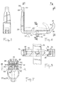
- - la figure 1 est une perspective montrant, en vue arrière, un siège auto enfant monté sur la banquette arrière d'un véhicule, maintenu en place pour l'une des ceintures de sécurité arrière et fixé au moyen du dispositif de l'invention,
- - les figures 2 et 3 sont des vues analogues à la figure 1 illustrant deux variantes de réalisation du dispositif.
- - la figure 4 est une élévation latérale d'une pince mise en oeuvre dans le dispositif,
- - la figure 5 est une vue de dessus prise suivant la ligne V-V de la figure 4,
- - la figure 6 est une vue en bout prise suivant la ligne VI-VI de la figure 4,
- - la figure 7 est une coupe prise suivant la ligne VII-VII de la figure 4 avec, en trait mixte, la fixation sur un méplat postérieur du piètement et sur un tube ascendant dudit piètement.
- FIG. 1 is a perspective showing, in rear view, a child car seat mounted on the rear seat of a vehicle, held in place for one of the rear seat belts and fixed by means of the device of the invention,
- - Figures 2 and 3 are views similar to Figure 1 illustrating two alternative embodiments of the device.
- FIG. 4 is a side elevation of a clamp used in the device,
- - Figure 5 is a top view taken along the line VV of figure 4,
- FIG. 6 is an end view taken on line VI-VI of FIG. 4,
- - Figure 7 is a section taken along the line VII-VII of Figure 4 with, in phantom, the fixing on a posterior flat of the base and on an ascending tube of said base.
Ainsi que le montre la figure 1, le siège auto enfant comporte une coque 1 en matière plastique armée munie d'un revêtement confortable 2 pour recevoir l'enfant et d'un harnais de sécurité 3 pour l'y maintenir en place.As shown in Figure 1, the child car seat has a
La coque 1 fait corps avec un piètement 4. La piètement 4 présente la forme générale d'un V dont une branche 5 sensiblement horizontale est destinée à reposer sur l'assise de la banquette 6 du véhicule et dont une branche 7 sensiblement verticale est destinée à s'appuyer en coopération avec le dos de la coque contre le dossier, non représenté de ladite banquette. Un passage 8 est ménagé entre la coque 1 et le piètement 4 pour être traversé, de la manière décrite dans ce qui suit, par la ceinture de sécurité 9 du véhicule. Cette ceinture 9 est d'un seul morceau ; l'une de ses extrémités 10 est fixée à un point d'attache du véhicule, tandis que son autre extrémité 11 coopère avec un enrouleur autobloquant porté par ledit véhicule. Sur la ceinture est monté coulissant un pène 12 susceptible d'être verrouillé dans une boucle 13 attachée à un autre point du véhicule. Dans cette position de verrouillage, la ceinture 9 traverse le passage 8 et présente, de part et d'autre du pène 12, une sangle sous-abdominale 14 et une sangle baudrier 15 ; la sangle sous-abdominale 14 s'appuie sur la branche d'assise 5 du piètement et la sangle baudrier 15 s'appuie dans l'angle 16 qui est opposé au pène 12 et que forme le haut de la branche dorsale 7 du piètement et la coque 1.The
Dans l'exemple représenté, le piètement 4 est monolithique et exécuté par cambrage d'un tube métallique. La branche d'assise 5 est constituée par une partie conformée en U dont l'élément médian 17 est situé à l'avant et dont les éléments latéraux 18, 19 sont cambrés en V pour former, au-delà de coudes 20, 21, des éléments ascendants inclinés 22, 23 constituant la branche dorsale 7. Les extrémités libres hautes de ces éléments ascendants sont fixées, par tous moyens appropriés 24, à une armature métallique intégrée de la coque 1, non visible sur le dessin.In the example shown, the
En raison de cette conformation, lorsque la branche 5 repose sur l'assise 6 de la banquette, le piètement 4 bute par ses coudes 20, 21 contre le dossier de la banquette et le dos de la coque 1 contre ledit dossier.Because of this conformation, when the
Dans cet exemple, la sangle sous abdominale 14 s'appuie sur les éléments tubulaires latéraux 18, 19 du piètement et la sangle baudrier 15 dans l'angle supérieur 16 précité pour presser le siège bébé contre la banquette.In this example, the
Selon l'invention et ainsi que cela ressort de la figure 1, une pince ouvrante 25 assure la fixation démontable de la sangle sous abdominale 14 sur une traverse 26 reliant près des coudes 20, 21 les éléments latéraux bas 18, 19 du piètement. Cette pince doit être ouvrante pour qu'en position d'ouverture (position représentée en trait plein sur la figure 4), la sangle 14 puisse être facilement engagée ou dégagée et qu'en position de fermeture (position représentée en trait mixte sur la figure 4), ladite sangle puisse être fermement pincée et immobilisée par rapport au piètement.According to the invention and as is apparent from Figure 1, an
Dans l'exemple représenté sur les figures 4 à 7, la pince 25 est en matière plastique moulée. Elle comporte :
- un mors fixe 27 s'étendant perpendiculairement à la traverse 26 et fixé à celle-ci par un boulon 28 ou tout autre moyen approprié,
- un mors ouvrant 29 monté pivotant sur l'une des extrémités du mors fixe 27 ; à cet effet, le mors fixe 27 et le mors ouvrant 29 présentent respectivement une chape 30 et un oeilleton 31 emboîtés l'un dans l'autre et traversés par un axe d'articulation 32 (figure 5), la disposition inverse étant évidemment possible,
- et un levier de verrouillage 33 monté pivotant sur l'autre extrémité du mors fixe 27 par des moyens analogues aux précédents : une chape 34, un oeilleton 35 et un axe d'articulation 36, mais dans la disposition inverse.In the example shown in Figures 4 to 7, the
a fixed
- An
- And a locking
En effet, l'oeilleton 35 est venu de moulage avec le mors fixe 27 et la chape 34 avec le levier 34. Les branches de cette chape sont relativement longues pour permettre l'emboîtement de celle-ci sur un bec terminal de verrouillage 37 venu de moulage avec le mors ouvrant 29. L'âme 38 de la chape 34 coopère alors avec une rampe 39 du bec pour assurer le pincement de la sangle 14 entre les deux mors 27 et 29 et se verrouille dans un cran 40 faisant suit au bec 37. L'âme 38 est prolongée par un doigt de manoeuvre 41.Indeed, the
Pour pincer la sangle 14, le mors fixe 27 présente deux bordures marginales 42 séparées par une rainure médiane 43 et le mors ouvrant 29 deux rainures marginales 44 séparées par une nervure médiane 45, les bordures 42 étant susceptibles de pénétrer lors de la fermeture de la pince dans la rainure 43 et la nervure 45 pénétrant alors dans la rainure 45 ; ainsi, et comme le montre la figure 7, la sangle 14 se trouve pincée en prenant un profil sinueux mieux apte encore à empêcher le glissement du siège le long de ladite sangle.To pinch the
Il peut être avantageux d'immobiliser le boulon 28. A cet effet, la tête de vis 46 de ce boulon est circulaire et bombée et présente deux méplats. Elle est alors logée dans un évidement 47 délimité en creux dans le fond de la rainure 43.It may be advantageous to immobilize the
Dans l'exemple représenté, la pince 25 est positionnée au milieu de la traverse 26 et à cet effet, le boulon 28 est engagé dans un trou de celle-ci.In the example shown, the
Il peut être avantageux, pour adapter la fixation aux différentes configurations des ceintures de sécurité des véhicules, de régler le positionnement de la pince 25. Pour cela, divers moyens peuvent être mis en oeuvre. Par exemple, plusieurs trous peuvent être prévus dans la traverse 26 pour le passage du boulon 28 ou bien, la traverse peut présenter une lumière longitudinale à bords dentés comme une crémaillère, pour le logement d'un taquet formé en saillie sous le mors fixe 27 et traversé par la tige du boulon.It may be advantageous, in order to adapt the attachment to the different configurations of the vehicle seat belts, to adjust the positioning of the
Les moyens décrits dans ce qui précède en se référant à la figure 1, permettent de bloquer le siège enfant sur la sangle sous abdominale 14.The means described in the foregoing with reference to FIG. 1 make it possible to block the child seat on the
L'enrouleur se dévide faiblement notamment lorsque l'enfant remue, de sorte que la sangle baudrier 15 prend du mou et que le siège enfant, bien que maintenu en position par la sangle sous-abdominale 14, tend à se soulever légèrement du côté du pène 12. Il revient à sa position, la sangle 15 se rembobinant, lorsque l'enfant cesse de remuer.The retractor unwinds slightly, especially when the child is moving, so that the
Il peut être avantageux de s'opposer, non seulement à la mobilité latérale, mais également à la tendance au soulèvement, sans pour autant neutraliser l'action de l'enrouleur en cas de choc.It can be advantageous to oppose not only lateral mobility, but also the tendency to lift, without neutralizing the action of the retractor in the event of an impact.
A cet effet, la sangle baudrier 15 est immobilisée au-dessus du pène 12.To this end, the
Suivant une première forme de réalisation illustrée par les figures 2 et 7, deux autres pinces 48 et 49, analogues à la pince 25, sont prévues. Leurs mors fixes 27 sont fixés sur les côtés des éléments ascendants inclinés 22 et 23 du piètement vers la coque 1, au voisinage des angles 16 précités. Ces pinces sont sélectivement utilisées en fonction de l'emplacement gauche ou droit occupé par le siège. En fait, la pince utilisée est celle qui est située à l'opposé du pène 12 et dans l'exemple représenté sur la figure 2, il s'agit de la pince gauche 48 étant donné que le siège occupe l'emplacement gauche de la banquette. Pour faciliter la fixation de ces pinces 48 et 49 sur les tubes 22 et 23 du piètement, le mors fixe 27 desdites pinces présente en-dessous (figures 4 et 7) deux bordures d'appui 50 séparées par un évidement longitudinal 51.According to a first embodiment illustrated in Figures 2 and 7, two
Suivant une deuxième forme de réalisation illustrée par la figure 5, une pince flottante unique 52 est prévue, son mors ouvrant 29 étant attaché par un lien souple 53 à la traverse 26 du piètement, de façon à être imperdable et toujours reliée au siège lors de ses manipulations. Dans ce cas, lorsque la sangle sous abdominale 14 est tendue en tirant sur le pène 12 par la sangle baudrier 15, la pince 50 est posée sur cette sangle baudrier près du pène pour empêcher la sangle sous abdominale 14 de se détendre si l'enrouleur se dévide un peu.According to a second embodiment illustrated in FIG. 5, a single floating
Il est bien évident que le piètement 4 peut ne pas être fabriqué en tube métallique. Il peut être en tôle métallique emboutie et ajourée, en matière plastique moulée, en aggloméré de particules de bois etc ... L'important est que les pinces 25 et 48, 49 ou 52 puissent être fixées ou montées aux emplacements indiqués dans ce qui précède et que le passage 8 des sangles soit ménagé.It is obvious that the
Claims (5)
caractérisé en ce qu'une pince ouvrante (25) est montée sur le piètement (4-26) pour prendre la sangle sous abdominale (14) et la bloquer après positionnement latéral correct du siège sur la banquette.1.- Device for the safety fixing of a child car seat on a rear seat of a motor vehicle, the seat comprising a shell forming a body with a support base (4) partially shaped at least in V, the branch being substantially horizontal ( 5) is intended to rest on the seat (6) of the seat, while the substantially vertical branch (7) of this base and the back of the shell are applied against the back of the seat by a seat belt (9 ) of the self-locking retractable vehicle, belt which passes through a passage (8) formed between said shell and said base so that the sub-abdominal strap (14) of said belt bears on the substantially horizontal branch (5) of the base and that the shoulder strap (15) of this belt bears against the top (16) of an edge of the substantially vertical branch of the base and the shell when the bolt (12) sliding on the belt at the limit of the two straps is locked in there e loop (13) attached to the vehicle,
characterized in that an opening clamp (25) is mounted on the base (4-26) to take the abdominal strap (14) and lock it after correct lateral positioning of the seat on the seat.
Applications Claiming Priority (2)
| Application Number | Priority Date | Filing Date | Title |
|---|---|---|---|
| FR8718185A FR2625145B1 (en) | 1987-12-24 | 1987-12-24 | DEVICE FOR SECURING A CHILD CAR SEAT TO A REAR BENCH OF A MOTOR VEHICLE |
| FR8718185 | 1987-12-24 |
Publications (2)
| Publication Number | Publication Date |
|---|---|
| EP0323334A1 true EP0323334A1 (en) | 1989-07-05 |
| EP0323334B1 EP0323334B1 (en) | 1993-02-17 |
Family
ID=9358325
Family Applications (1)
| Application Number | Title | Priority Date | Filing Date |
|---|---|---|---|
| EP19880403307 Expired - Lifetime EP0323334B1 (en) | 1987-12-24 | 1988-12-23 | Apparatus for the safe attachment of an infant's vehicle seat to the rear seat of an automotive vehicle |
Country Status (4)
| Country | Link |
|---|---|
| EP (1) | EP0323334B1 (en) |
| DE (2) | DE323334T1 (en) |
| ES (1) | ES2010978T3 (en) |
| FR (1) | FR2625145B1 (en) |
Cited By (18)
| Publication number | Priority date | Publication date | Assignee | Title |
|---|---|---|---|---|
| FR2649367A1 (en) * | 1989-07-06 | 1991-01-11 | Baby Relax | CHILD CAR SEAT DEVICE AND METHOD FOR MANUFACTURING THE SAME |
| EP0452804A2 (en) * | 1990-04-18 | 1991-10-23 | Margarete Schräder | Child's safety seat for motor vehicles |
| FR2699469A1 (en) * | 1992-12-23 | 1994-06-24 | Peugeot | Child's safety seat with dashboard mounting |
| DE4303247A1 (en) * | 1993-02-04 | 1994-08-11 | Osann Design Entwicklungs Und | Child safety seat |
| EP0676309A1 (en) * | 1994-03-24 | 1995-10-11 | Britax-Excelsior Limited | Infant safety seat for motor vehicles |
| NL9500514A (en) * | 1995-03-15 | 1996-10-01 | Mach En Metaalfab Oedremefaoe | Child's safety seat |
| FR2741847A1 (en) * | 1995-12-05 | 1997-06-06 | Baby Relax | System for attachment of child's seat to seat frame in vehicle |
| EP0813992A2 (en) * | 1996-06-19 | 1997-12-29 | Margarete Schräder | Infant seat for passenger transport vehicles |
| FR2750371A1 (en) * | 1996-06-28 | 1998-01-02 | Ampafrance | CHILD SEAT FOR FIXING ON A VEHICLE SEAT USING A SEAT BELT |
| EP0818346A2 (en) | 1996-07-09 | 1998-01-14 | Margarete Schräder | Infant seat in particular for automotive vehicles |
| EP1110806A1 (en) * | 1999-12-21 | 2001-06-27 | Combi Corporation | Child car seat |
| EP1232902A3 (en) * | 2001-02-17 | 2003-05-14 | BRITAX RÖMER Kindersicherheit GmbH | Child safety seat |
| EP1088695A3 (en) * | 1999-09-30 | 2003-07-09 | Combi Corporation | Locking clip |
| KR100871360B1 (en) * | 2000-10-16 | 2008-12-02 | 콤비 가부시키가이샤 | Child car seat and belt locking apparatus used therefor |
| CN101508254B (en) * | 2008-02-15 | 2014-05-14 | 高田株式会社 | Child seat |
| US8845022B2 (en) | 2012-09-04 | 2014-09-30 | Britax Child Safety, Inc. | Child seat with belt tensioning mechanism for improved installation |
| US9499074B2 (en) | 2013-10-25 | 2016-11-22 | Britax Child Safety, Inc. | Forward and rearward facing child seat with belt tensioning mechanism for improved installation |
| US20190193604A1 (en) * | 2017-12-21 | 2019-06-27 | BRITAX RÖMER Kindersicherheit GmbH | Child safety seat with belted pivot link |
Families Citing this family (1)
| Publication number | Priority date | Publication date | Assignee | Title |
|---|---|---|---|---|
| FR2959178B1 (en) * | 2010-04-22 | 2012-07-06 | Peugeot Citroen Automobiles Sa | VEHICLE SEAT INCORPORATING A SEAT FOR A RETRACTABLE CHILD |
Citations (5)
| Publication number | Priority date | Publication date | Assignee | Title |
|---|---|---|---|---|
| DE1937610A1 (en) * | 1969-07-24 | 1971-02-11 | Opel Adam Ag | Arrangement for fastening child seats in motor vehicles |
| US3922035A (en) * | 1974-08-09 | 1975-11-25 | Hyman Wener | Safety vehicle seat structure |
| US4339149A (en) * | 1979-04-10 | 1982-07-13 | Combi Co., Ltd. | Child's automotive safety seat |
| US4591208A (en) * | 1973-03-22 | 1986-05-27 | Bobby-Mac Company, Inc. | Safety shield for use in a vehicle |
| FR2602409A1 (en) * | 1986-08-11 | 1988-02-12 | Ampafrance | Child's seat for a motor vehicle |
-
1987
- 1987-12-24 FR FR8718185A patent/FR2625145B1/en not_active Expired - Lifetime
-
1988
- 1988-12-23 ES ES198888403307T patent/ES2010978T3/en not_active Expired - Lifetime
- 1988-12-23 DE DE1988403307 patent/DE323334T1/en active Pending
- 1988-12-23 EP EP19880403307 patent/EP0323334B1/en not_active Expired - Lifetime
- 1988-12-23 DE DE19883878549 patent/DE3878549T2/en not_active Expired - Fee Related
Patent Citations (5)
| Publication number | Priority date | Publication date | Assignee | Title |
|---|---|---|---|---|
| DE1937610A1 (en) * | 1969-07-24 | 1971-02-11 | Opel Adam Ag | Arrangement for fastening child seats in motor vehicles |
| US4591208A (en) * | 1973-03-22 | 1986-05-27 | Bobby-Mac Company, Inc. | Safety shield for use in a vehicle |
| US3922035A (en) * | 1974-08-09 | 1975-11-25 | Hyman Wener | Safety vehicle seat structure |
| US4339149A (en) * | 1979-04-10 | 1982-07-13 | Combi Co., Ltd. | Child's automotive safety seat |
| FR2602409A1 (en) * | 1986-08-11 | 1988-02-12 | Ampafrance | Child's seat for a motor vehicle |
Cited By (34)
| Publication number | Priority date | Publication date | Assignee | Title |
|---|---|---|---|---|
| FR2649367A1 (en) * | 1989-07-06 | 1991-01-11 | Baby Relax | CHILD CAR SEAT DEVICE AND METHOD FOR MANUFACTURING THE SAME |
| EP0408415A1 (en) * | 1989-07-06 | 1991-01-16 | BABY RELAX Société en nom collectif | Child's car seat and process for making same |
| EP0452804A2 (en) * | 1990-04-18 | 1991-10-23 | Margarete Schräder | Child's safety seat for motor vehicles |
| EP0452804A3 (en) * | 1990-04-18 | 1993-03-03 | Margarete Schraeder | Child's safety seat for motor vehicles |
| FR2699469A1 (en) * | 1992-12-23 | 1994-06-24 | Peugeot | Child's safety seat with dashboard mounting |
| DE4303247A1 (en) * | 1993-02-04 | 1994-08-11 | Osann Design Entwicklungs Und | Child safety seat |
| EP0676309A1 (en) * | 1994-03-24 | 1995-10-11 | Britax-Excelsior Limited | Infant safety seat for motor vehicles |
| US5567007A (en) * | 1994-03-24 | 1996-10-22 | Britax Romer Kindersicherheit Gmbh | Infant safety seat |
| NL9500514A (en) * | 1995-03-15 | 1996-10-01 | Mach En Metaalfab Oedremefaoe | Child's safety seat |
| FR2741847A1 (en) * | 1995-12-05 | 1997-06-06 | Baby Relax | System for attachment of child's seat to seat frame in vehicle |
| EP0813992A3 (en) * | 1996-06-19 | 1999-10-27 | Margarete Schräder | Infant seat for passenger transport vehicles |
| EP0813992A2 (en) * | 1996-06-19 | 1997-12-29 | Margarete Schräder | Infant seat for passenger transport vehicles |
| EP0816161A1 (en) * | 1996-06-28 | 1998-01-07 | Ampafrance S.A. | Children seat to be fixed on a vehicle seat by means of a safety belt |
| US5810435A (en) * | 1996-06-28 | 1998-09-22 | Ampafrance S.A. | Child seat intended to be fastened to a vehicle seat by means of a safety belt |
| FR2750371A1 (en) * | 1996-06-28 | 1998-01-02 | Ampafrance | CHILD SEAT FOR FIXING ON A VEHICLE SEAT USING A SEAT BELT |
| EP0818346A2 (en) | 1996-07-09 | 1998-01-14 | Margarete Schräder | Infant seat in particular for automotive vehicles |
| EP0818346A3 (en) * | 1996-07-09 | 1998-11-18 | Margarete Schräder | Infant seat in particular for automotive vehicles |
| EP1088695A3 (en) * | 1999-09-30 | 2003-07-09 | Combi Corporation | Locking clip |
| EP1110806A1 (en) * | 1999-12-21 | 2001-06-27 | Combi Corporation | Child car seat |
| US6508510B2 (en) | 1999-12-21 | 2003-01-21 | Combi Corporation | Child car seat |
| KR100871360B1 (en) * | 2000-10-16 | 2008-12-02 | 콤비 가부시키가이샤 | Child car seat and belt locking apparatus used therefor |
| EP1232902A3 (en) * | 2001-02-17 | 2003-05-14 | BRITAX RÖMER Kindersicherheit GmbH | Child safety seat |
| CN101508254B (en) * | 2008-02-15 | 2014-05-14 | 高田株式会社 | Child seat |
| US8845022B2 (en) | 2012-09-04 | 2014-09-30 | Britax Child Safety, Inc. | Child seat with belt tensioning mechanism for improved installation |
| US9187016B2 (en) | 2012-09-04 | 2015-11-17 | Britax Child Safety Inc. | Child seat with belt tensioning mechanism for improved installation |
| US9963051B2 (en) | 2013-10-25 | 2018-05-08 | Britax Child Safety, Inc. | Forward and rearward facing child seat with belt tensioning mechanism for improved installation |
| US9586504B2 (en) | 2013-10-25 | 2017-03-07 | Britax Child Safety, Inc. | Forward and rearward facing child seat with belt tensioning mechanism for improved installation |
| US9499074B2 (en) | 2013-10-25 | 2016-11-22 | Britax Child Safety, Inc. | Forward and rearward facing child seat with belt tensioning mechanism for improved installation |
| US11117498B2 (en) | 2013-10-25 | 2021-09-14 | Britax Child Safety, Inc. | Forward and rearward facing child seat with belt tensioning mechanism for improved installation |
| US11491897B2 (en) | 2013-10-25 | 2022-11-08 | Britax Child Safety, Inc. | Forward and rearward facing child seat with belt tensioning mechanism for improved installation |
| US20190193604A1 (en) * | 2017-12-21 | 2019-06-27 | BRITAX RÖMER Kindersicherheit GmbH | Child safety seat with belted pivot link |
| CN110001471A (en) * | 2017-12-21 | 2019-07-12 | 宝得适罗姆儿童安全有限公司 | The child safety seat being pivotally connected with belt |
| US10899252B2 (en) * | 2017-12-21 | 2021-01-26 | BRITAX RÖMER Kindersicherheit GmbH | Child safety seat with belted pivot link |
| EP3501888B1 (en) * | 2017-12-21 | 2021-05-12 | BRITAX RÖMER Kindersicherheit GmbH | Child safety seat with belted pivot link |
Also Published As
| Publication number | Publication date |
|---|---|
| EP0323334B1 (en) | 1993-02-17 |
| DE3878549T2 (en) | 1993-06-03 |
| FR2625145B1 (en) | 1990-06-08 |
| DE3878549D1 (en) | 1993-03-25 |
| FR2625145A1 (en) | 1989-06-30 |
| ES2010978T3 (en) | 1993-10-01 |
| ES2010978A4 (en) | 1989-12-16 |
| DE323334T1 (en) | 1990-02-08 |
Similar Documents
| Publication | Publication Date | Title |
|---|---|---|
| EP0323334B1 (en) | Apparatus for the safe attachment of an infant's vehicle seat to the rear seat of an automotive vehicle | |
| EP0363261B1 (en) | Reinforced frame for a vehicle seat | |
| FR2591964A1 (en) | CHILD SAFETY SEAT | |
| FR2645806A1 (en) | CHILD SEAT FOR VEHICLE AND ASSEMBLY FORMING SECURITY BELT | |
| EP1222090A1 (en) | Child safety device adaptable on a vehicle | |
| FR2673148A1 (en) | REMOVABLE SEAT OF VEHICLE. | |
| FR2504876A1 (en) | DEVICE FOR ANCHORING A SAFETY STRAP IN A VEHICLE | |
| EP0176404A1 (en) | Universal carrier cross-bar for a vehicle with or without gutter | |
| EP3164296B1 (en) | Device for carrying a child in a vehicle and including a translatably mountable base and bassinet, and corresponding base and bassinet | |
| FR2808485A1 (en) | RATCHET FOR FIXING A CHILD CAR SEAT LOCKING STRAP, MATCHING HOOK AND ADJUSTING ADJUSTMENT MEMBER | |
| FR2859433A1 (en) | SEAT WITH INTEGRATED SAFETY BELT OF A MOTOR VEHICLE | |
| FR3128257A1 (en) | Fixing Strap Clamp Assembly | |
| WO2023007475A1 (en) | Vehicle seat backrest equipped with an airbag device and vehicle seat comprising such a backrest | |
| WO1993021044A1 (en) | Safety belt system and suitable strap | |
| FR2684612A1 (en) | DEVICE FOR ADJUSTING THE LOCKING POSITION OF A FASTENING MEANS IN A SEAT BELT DEVICE. | |
| FR2929186A1 (en) | Sliding support controlling device for headrest of seat of motor vehicle, has block integrated to armature having median part extended by metal rods, and including spring expanded to escape pin to exterior of groove and release support | |
| FR2796344A1 (en) | Automobile rear seat anchoring and articulation mechanism comprises cheek web connected to seat part, with web immobilizer comprising two hooks clamping pegs integral with floor | |
| FR2686230A1 (en) | SAFETY HELMET EQUIPPED WITH ATTACHMENT PIECES OF AN ACCESSORY. | |
| FR2723556A1 (en) | Vehicle seat belt length adjuster | |
| EP1043180A1 (en) | Roller blind with handle and indexed hooks, and process for producing the same | |
| WO2006013300A1 (en) | Retaining means arrangement inside a motor vehicle | |
| FR2959461A1 (en) | Rear retractable shelf for motor vehicle, has maintaining unit whose finger is projected from shelf and arranged with respect to end of flexible cord such that finger threads up loop of cord on finger in removable manner | |
| WO2006064152A1 (en) | Adjustable clasp bodies for a safety belt | |
| FR2778882A1 (en) | Seat belt fixture for motor vehicle seat with head rest | |
| FR2695887A1 (en) | Child's car seat - has rigid one-piece frame with interchangeable padded covers to fit children of different sizes |
Legal Events
| Date | Code | Title | Description |
|---|---|---|---|
| PUAI | Public reference made under article 153(3) epc to a published international application that has entered the european phase |
Free format text: ORIGINAL CODE: 0009012 |
|
| AK | Designated contracting states |
Kind code of ref document: A1 Designated state(s): DE ES FR GB IT |
|
| RBV | Designated contracting states (corrected) |
Designated state(s): DE ES GB IT |
|
| ITCL | It: translation for ep claims filed |
Representative=s name: RICCARDI SERGIO & CO. |
|
| GBC | Gb: translation of claims filed (gb section 78(7)/1977) | ||
| 17P | Request for examination filed |
Effective date: 19891201 |
|
| DET | De: translation of patent claims | ||
| 17Q | First examination report despatched |
Effective date: 19920115 |
|
| GRAA | (expected) grant |
Free format text: ORIGINAL CODE: 0009210 |
|
| AK | Designated contracting states |
Kind code of ref document: B1 Designated state(s): DE ES GB IT |
|
| GBT | Gb: translation of ep patent filed (gb section 77(6)(a)/1977) |
Effective date: 19930216 |
|
| REF | Corresponds to: |
Ref document number: 3878549 Country of ref document: DE Date of ref document: 19930325 |
|
| ITF | It: translation for a ep patent filed |
Owner name: UFFICIO BREVETTI RICCARDI & C. |
|
| REG | Reference to a national code |
Ref country code: ES Ref legal event code: FG2A Ref document number: 2010978 Country of ref document: ES Kind code of ref document: T3 |
|
| PLBE | No opposition filed within time limit |
Free format text: ORIGINAL CODE: 0009261 |
|
| STAA | Information on the status of an ep patent application or granted ep patent |
Free format text: STATUS: NO OPPOSITION FILED WITHIN TIME LIMIT |
|
| 26N | No opposition filed | ||
| PGFP | Annual fee paid to national office [announced via postgrant information from national office to epo] |
Ref country code: GB Payment date: 19941216 Year of fee payment: 7 |
|
| PGFP | Annual fee paid to national office [announced via postgrant information from national office to epo] |
Ref country code: ES Payment date: 19941221 Year of fee payment: 7 |
|
| PGFP | Annual fee paid to national office [announced via postgrant information from national office to epo] |
Ref country code: DE Payment date: 19941224 Year of fee payment: 7 |
|
| PG25 | Lapsed in a contracting state [announced via postgrant information from national office to epo] |
Ref country code: GB Effective date: 19951223 |
|
| PG25 | Lapsed in a contracting state [announced via postgrant information from national office to epo] |
Ref country code: ES Free format text: LAPSE BECAUSE OF THE APPLICANT RENOUNCES Effective date: 19951226 |
|
| GBPC | Gb: european patent ceased through non-payment of renewal fee |
Effective date: 19951223 |
|
| PG25 | Lapsed in a contracting state [announced via postgrant information from national office to epo] |
Ref country code: DE Effective date: 19960903 |
|
| REG | Reference to a national code |
Ref country code: ES Ref legal event code: FD2A Effective date: 20010402 |
|
| PG25 | Lapsed in a contracting state [announced via postgrant information from national office to epo] |
Ref country code: IT Free format text: LAPSE BECAUSE OF NON-PAYMENT OF DUE FEES;WARNING: LAPSES OF ITALIAN PATENTS WITH EFFECTIVE DATE BEFORE 2007 MAY HAVE OCCURRED AT ANY TIME BEFORE 2007. THE CORRECT EFFECTIVE DATE MAY BE DIFFERENT FROM THE ONE RECORDED. Effective date: 20051223 |