EP0452804A2 - Child's safety seat for motor vehicles - Google Patents
Child's safety seat for motor vehicles Download PDFInfo
- Publication number
- EP0452804A2 EP0452804A2 EP91105741A EP91105741A EP0452804A2 EP 0452804 A2 EP0452804 A2 EP 0452804A2 EP 91105741 A EP91105741 A EP 91105741A EP 91105741 A EP91105741 A EP 91105741A EP 0452804 A2 EP0452804 A2 EP 0452804A2
- Authority
- EP
- European Patent Office
- Prior art keywords
- safety seat
- clamping
- frame
- child safety
- clamping bar
- Prior art date
- Legal status (The legal status is an assumption and is not a legal conclusion. Google has not performed a legal analysis and makes no representation as to the accuracy of the status listed.)
- Granted
Links
- 239000002131 composite material Substances 0.000 claims description 17
- 239000002184 metal Substances 0.000 claims description 3
- 230000001133 acceleration Effects 0.000 description 1
- 230000006978 adaptation Effects 0.000 description 1
- 238000005452 bending Methods 0.000 description 1
- 230000005484 gravity Effects 0.000 description 1
- 230000002787 reinforcement Effects 0.000 description 1
- 230000000452 restraining effect Effects 0.000 description 1
Images


Classifications
-
- B—PERFORMING OPERATIONS; TRANSPORTING
- B60—VEHICLES IN GENERAL
- B60N—SEATS SPECIALLY ADAPTED FOR VEHICLES; VEHICLE PASSENGER ACCOMMODATION NOT OTHERWISE PROVIDED FOR
- B60N2/00—Seats specially adapted for vehicles; Arrangement or mounting of seats in vehicles
- B60N2/24—Seats specially adapted for vehicles; Arrangement or mounting of seats in vehicles for particular purposes or particular vehicles
- B60N2/26—Seats specially adapted for vehicles; Arrangement or mounting of seats in vehicles for particular purposes or particular vehicles for children
- B60N2/28—Seats readily mountable on, and dismountable from, existing seats or other parts of the vehicle
- B60N2/2857—Seats readily mountable on, and dismountable from, existing seats or other parts of the vehicle characterised by the peculiar orientation of the child
- B60N2/286—Seats readily mountable on, and dismountable from, existing seats or other parts of the vehicle characterised by the peculiar orientation of the child forward facing
-
- B—PERFORMING OPERATIONS; TRANSPORTING
- B60—VEHICLES IN GENERAL
- B60N—SEATS SPECIALLY ADAPTED FOR VEHICLES; VEHICLE PASSENGER ACCOMMODATION NOT OTHERWISE PROVIDED FOR
- B60N2/00—Seats specially adapted for vehicles; Arrangement or mounting of seats in vehicles
- B60N2/24—Seats specially adapted for vehicles; Arrangement or mounting of seats in vehicles for particular purposes or particular vehicles
- B60N2/26—Seats specially adapted for vehicles; Arrangement or mounting of seats in vehicles for particular purposes or particular vehicles for children
- B60N2/28—Seats readily mountable on, and dismountable from, existing seats or other parts of the vehicle
- B60N2/2803—Adaptations for seat belts
- B60N2/2806—Adaptations for seat belts for securing the child seat to the vehicle
Definitions
- the invention relates to a child safety seat for motor vehicles, comprising a frame which has two side parts connected to one another by composite struts, and a seat element carried by the frame, the safety seat being able to be parked on a seat of the motor vehicle and held in position by means of the vehicle's own belt system, at least a diagonal belt of the belt system can be non-positively fixed to the frame.
- a child seat can be found in DE-U 83 06 935, which can be fixed in the desired position by means of belt straps without additional fastener elements without slippage and easily detachable.
- the Frame clamping devices are provided with a clamping lever, which allows the belt to be pulled through for tensioning, but blocks the belt in the opposite direction.
- DE-A 35 05 009 also describes a safety seat for children, which can be fixed with the aid of the vehicle's own diagonal belt.
- clamping devices are provided which have a manually operable eccentric for fixing the seat on the diagonal belt by clamping.
- a clamping device for the diagonal belt is provided on at least one composite strut provided in the region of the backrest of the seat element, which is located between the side parts of the frame.
- a clamping bar can be provided which forms a clamping gap with the composite strut for receiving the diagonal belt.
- the clamping bar can be pivotally mounted on a bracket at one end and can be operatively connected at its other end to a releasable locking element, which can be a lock part which overlaps the clamping bar at its free end and which can be on the Composite strut in the sense of increasing the distance to the holder can be arranged displaceably against the force of a spring.
- a particularly simple handling of the clamping device results if the free end of the clamping bar is provided with a beveled end face which displaces the lock part against the spring while the clamping bar is being moved into the clamping position until it reaches the clamping position by expanding the spring in one End position of the clamp bar is brought.
- the clamping bar can consist of a plastic part, which can be provided with a metal core in order to achieve the necessary bending rigidity.
- the clamping bar can be designed on its side facing the composite strut with its cross-sectional shape adapted to the profile.
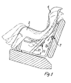
- the proposed safety seat consists essentially of a frame 1 with a seat element 2 attached to it.
- the frame 1 is preferably designed as a tubular frame and consists of two supporting side parts 3 and 4, which by a number Composite struts 5 are interconnected.
- the seat element 2 is arranged in a suitable manner in the frame frame 1 so as to be adjustable in height and inclination.
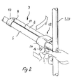
- One of the struts 5 is provided at the level of the central region of the backrest 6 of the seat element 2. It goes freely behind the seat element 2 and, according to FIG. 2, is provided with a clamping device 7.
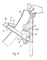
- This consists of a clamping bar 8 which, as can be seen from FIG. 3, is pivotably mounted at one end 9 on a clamp-like holder 10.
- the holder is permanently connected to the composite strut 5.
- the clamping bar can be provided with a metal reinforcement core.
- the clamping bar 8 is concave on its side facing the composite strut 5 in adaptation to the circular cross section thereof and forms a clamping gap 11 when in contact with the composite strut 5.
- the contact position is fixed by a locking element 12 which is connected to the free end 13 of the clamping bar 8 in Active connection occurs.
- the locking element 12 consists of a lock part 14 which can be displaced against the force of a spring 15 over a path length which, on the one hand, enables the clamping bar 8 to unfold unhindered and, on the other hand, secures the same.
- the locking element 12 is guided against rotation with respect to the composite strut 5.
- the length of the clamping device (7) can be a multiple of the width of the diagonal belt to be clamped with it of the vehicle's three-point belt system.
- actuating the locking element 12 it is provided with a suitable handle 16, preferably in the form of a finger eyelet.
- a suitable handle 16 preferably in the form of a finger eyelet.
- the end face 17 is chamfered at the free end 13 of the clamping bar 8, such that the lock part 14 is displaced when the clamping bar 8 is brought into the clamping position against the spring 17 until it reaches the clamping position by expansion of the spring 15 slides over the free end 13 of the clamping bar 8 and fixes it.
- the child seat To fix the child seat, it is parked on the motor vehicle seat and brought to bear against the backrest. Then, according to FIGS. 5, 6 and 7, the belt parts 18, 19 of the vehicle's own three-point belt system in the lower region of the frame 1 are passed between the upstanding struts of the side parts 3 and 4 and the seat element 2 and locked in a lock 20 (FIG. 7). Then the clamping device 7 is opened by pulling back the lock part 14 and unfolding the clamping bar 8, and the diagonal belt 19 is inserted. After this has taken its tightened position by retraction by the automatic belt system, the clamping device 7 is now brought into the clamping position by folding in the clamping bar 8, in which it automatically engages with respect to the locking element 12.
- the diagonal belt 19 is thus clamped in the clamping gap 11 between the clamping bar 8 and the composite strut 5 and is able to immovably fix the seat together with the lap belt 18.
- the child safety seat shown can be equipped with additional belt clamps for separate belts for optional fixing.
- 1 shows that the side parts 3, 4 of the frame 1 are inclined Stiffening struts (21) are provided, on each of which there is an additional belt clamp 22.
- the two belt clamps 22 can be of a known type, but can also be designed in accordance with the clamping device 7 described above.
Abstract
Description
Die Erfindung betrifft einen Kindersicherheitssitz für Kraftfahrzeuge, umfassend ein Rahmengestell, das zwei durch Verbundstreben miteinander verbundene Seitenteile aufweist, und ein vom Rahmengestell getragenes Sitzelement, wobei der Sicherheitssitz auf einem Sitz des Kraftfahrzeuges abstellbar und mittels des fahrzeugeigenen Gurtsystems in seiner Position gehalten wird, wobei mindestens ein Diagonalgurt des Gurtsystems an dem Rahmengestell kraftschlüssig festlegbar ist.The invention relates to a child safety seat for motor vehicles, comprising a frame which has two side parts connected to one another by composite struts, and a seat element carried by the frame, the safety seat being able to be parked on a seat of the motor vehicle and held in position by means of the vehicle's own belt system, at least a diagonal belt of the belt system can be non-positively fixed to the frame.
Derartige Sicherheitssitze finden sich in vielfältigen Ausführungen im Stand der Technik. So ist aus dem DE-U 83 06 935 ein Kindersitz zu entnehmen, der durch Gurtbänder ohne zusätzliche Verschlußelemente schlupffrei und leicht lösbar in der gewünschten Lage festgelegt werden kann. Dazu sind an dem Gestell Klemmeinrichtungen mit einem Klemmhebel vorgesehen, der das Durchziehen des Gurtes zum Spannen ermöglicht, den Gurt aber in Gegenzugrichtung blockiert.Such safety seats can be found in various designs in the prior art. A child seat can be found in DE-U 83 06 935, which can be fixed in the desired position by means of belt straps without additional fastener elements without slippage and easily detachable. For this are on the Frame clamping devices are provided with a clamping lever, which allows the belt to be pulled through for tensioning, but blocks the belt in the opposite direction.
In der DE-A 35 05 009 ist weiter ein Sicherheitssitz für Kinder beschrieben, der unter Zuhilfenahme des fahrzeugeigenen Diagonalgurtes festlegbar ist. Dazu sind neben Durchführungen für den Beckengurt an dem Gestell im Bereich der Lehne des Sitzelementes Klemmeinrichtungen vorgesehen, die einen handbetätigbaren Exzenter zum Festlegen des Sitzes an dem Diagonalgurt durch Klemmung aufweisen.DE-A 35 05 009 also describes a safety seat for children, which can be fixed with the aid of the vehicle's own diagonal belt. For this purpose, in addition to bushings for the lap belt on the frame in the region of the back of the seat element, clamping devices are provided which have a manually operable eccentric for fixing the seat on the diagonal belt by clamping.
Nachteilig ist bei diesen bekannten Systemen, daß die Gestelle ihre Position bei starker Verzögerung des Kraftfahrzeuges nicht sicher beibehalten. Dies rührt im Falle des erstgenannten Standes der Technik im wesentlichen daher, daß die Befestigung des Sitzes unterhalb des Schwerpunktes des besetzten Sitzes erfolgt, was eine erhebliche Nickbewegung desselben ermöglicht. Im zweiten Falle ergibt sich aufgrund der einseitigen Rückhaltung im Lehnenbereich eine "Verwindung" des Sitzes.A disadvantage of these known systems is that the racks do not reliably maintain their position when the motor vehicle is decelerated sharply. In the case of the first-mentioned prior art, this is essentially due to the fact that the seat is attached below the center of gravity of the occupied seat, which enables the latter to move significantly. In the second case, the seat is "twisted" due to the one-sided restraint in the backrest area.
Es ist die Aufgabe der Erfindung, Kindersicherheitssitze der einleitend angeführten Art so auszustatten, daß sie mindestens mit dem fahrzeugeigenen Dreipunkt-Gurtsystem unverrückbar festlegbar sind.It is the object of the invention to equip child safety seats of the type mentioned in the introduction such that they can be immovably fixed at least with the vehicle's three-point belt system.
Diese Aufgabe wird bei dem Kindersicherheitssitz der eingangs beschriebenen Art dadurch gelöst, daß an mindestens einer im Bereich der Rückenlehne des Sitzelementes vorgesehenen, am Rahmengestell angeordneten Verbundstrebe eine Klemmeinrichtung für den Diagonalgurt vorgesehen ist, die sich zwischen den Seitenteilen des Rahmengestells findet.This object is achieved in the child safety seat of the type described above in that a clamping device for the diagonal belt is provided on at least one composite strut provided in the region of the backrest of the seat element, which is located between the side parts of the frame.
Damit ist gewährleistet, daß der Sitz durch die in seiner vertikalen Symmetrieebene angreifenden Rückhaltekraft des Schräggurtes verwindungsfrei zurückgehalten wird, wodurch die Bewegungsmöglichkeit des Sitzes im Beanspruchsungsfalle vermindert oder stark herabgesetzt ist, das heißt daß gefährliche Beschleunigungen oder Bewegungen des Sitzes sicher unterbunden werden.This ensures that the seat is held torsion-free by the restraining force of the diagonal belt acting in its vertical plane of symmetry, which reduces or greatly reduces the possibility of movement of the seat in the event of stress, that is to say that dangerous accelerations or movements of the seat are reliably prevented.
Nach einer bevorzugten Ausgestaltung der Klemmeinrichtung kann ein Klemmbalken vorgesehen sein, der mit der Verbundstrebe einen Klemmspalt zur Aufnahme des Diagonalgurtes bildet. Zwecks einfacher Handhabung beim Befestigen des Sitzes kann der Klemmbalken an seinem einen Ende an einer Halterung schwenkbar gelagert sein und an seinem anderen Ende mit einem lösbaren Riegelelement in Wirkverbindung treten, wobei dieses ein den Klemmbalken an seinem freien Ende übergreifendes Schloßteil sein kann, welches auf der Verbundstrebe im Sinne einer Vergrößerung des Abstandes zu der Halterung gegen die Kraft einer Feder verschiebbar angeordnet sein kann.According to a preferred embodiment of the clamping device, a clamping bar can be provided which forms a clamping gap with the composite strut for receiving the diagonal belt. For easy handling when attaching the seat, the clamping bar can be pivotally mounted on a bracket at one end and can be operatively connected at its other end to a releasable locking element, which can be a lock part which overlaps the clamping bar at its free end and which can be on the Composite strut in the sense of increasing the distance to the holder can be arranged displaceably against the force of a spring.
Eine besonders einfache Handhabung der Klemmeinrichtung ergibt sich, wenn das freie Ende des Klemmbalkens mit einer abgeschrägten Stirnfläche versehen ist, die während des Verbringens des Klemmbalkens in Klemmstellung das Schloßteil gegen die Feder verdrängt, bis dieses bei Erreichen der Klemmstellung durch Expansion der Feder in einer das Ende des Klemmbalkens übergreifende Position gebracht wird.A particularly simple handling of the clamping device results if the free end of the clamping bar is provided with a beveled end face which displaces the lock part against the spring while the clamping bar is being moved into the clamping position until it reaches the clamping position by expanding the spring in one End position of the clamp bar is brought.
Zur Schonung des Gurtes kann der Klemmbalken aus einem Kunststoffteil bestehen, das zwecks Erzielung der notwendigen Biegesteifigkeit mit einem Metallkern versehen sein kann.To protect the belt, the clamping bar can consist of a plastic part, which can be provided with a metal core in order to achieve the necessary bending rigidity.
Um einerseits eine sichere Klemmung und andererseits eine Begrenzung der an dem Gurt wirksamen Flächenpressung zu erreichen, kann der Klemmbalken an seiner der Verbundstrebe zugekehrten Seite mit deren Querschnittsform angepaßter Profilierung ausgeführt sein.In order on the one hand to achieve secure clamping and on the other hand to limit the surface pressure effective on the belt, the clamping bar can be designed on its side facing the composite strut with its cross-sectional shape adapted to the profile.
Die Erfindung ist nachstehend anhand eines in den Zeichnungen dargestellten Ausführungsbeispieles näher erläutert. Es zeigen:
Figur 1- eine Seitenansicht des mit der erfindinngsgemäßen Klemmeinrichtung ausgestatteten Sitzes,
Figur 2- einen Ausschnitt aus dem das Sitzelement aufnehmenden Rahmengestell mit Blick auf eine mit der Klemmeinrichtung versehene Verbundstrebe im Bereich der Lehne des Sitzelementes,
Figur 3- die Klemmeinrichtung nach
Figur 2 im geöffnetem Zustand im Augenblick des Einlegens des Diagonalgurtes, - Figur 4
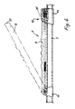
- eine Detaildarstellung der Klemmeinrichtung in Seitenansicht,
Figuren - in perspektivischer Teilansicht des Sitzes dessen Darstellung bei der Festlegung in der Anfangsphase, einer Zwischenphase und in der Endphase.
- Figure 1
- 2 shows a side view of the seat equipped with the clamping device according to the invention,
- Figure 2
- a section of the frame receiving the seat element with a view of a composite strut provided with the clamping device in the region of the back of the seat element,
- Figure 3
- 2 the clamping device according to FIG. 2 in the open state at the moment the diagonal belt is inserted,
- Figure 4
- a detailed view of the clamping device in side view,
- Figures 5, 6 and 7
- in a perspective partial view of the seat, the representation of the fixation in the initial phase, an intermediate phase and in the final phase.
Entsprechend Figur 1 besteht der vorgeschlagene Sicherheitssitz im wesentlichen aus einem Rahmengestell 1 mit einem an diesem befestigten Sitzelement 2. Das Rahmengestell 1 ist vorzugsweise als Rohrrahmen ausgebildet und besteht aus zwei stützenden Seitenteilen 3 und 4, die durch eine Anzahl Verbundstreben 5 miteinander verbunden sind. Das Sitzelement 2 ist auf geeignete Weise höhen- und neigungsverstellbar in dem Rahmengestell 1 angeordnet.According to Figure 1, the proposed safety seat consists essentially of a
Eine der Streben 5 ist in Höhe des Mittenbereichs der Rückenlehne 6 des Sitzelementes 2 vorgesehen. Sie geht hinter dem Sitzelement 2 frei und ist gemäß Figur 2 mit einer Klemmeinrichtung 7 versehen. Diese besteht aus einem Klemmbalken 8, der, wie aus Figur 3 ersichtlich, an seinem einen Ende 9 an einer schellenartigen Halterung 10 schwenkbar gelagert ist. Die Halterung ist mit der Verbundstrebe 5 unlösbar verbunden. Der Klemmbalken kann mit einem metallenen Verstärkungskern versehen sein.One of the
Der Klemmbalken 8 ist an seiner der Verbundstrebe 5 zugekehrten Seite in Anpassung an den Kreisquerschnitt derselben konkav ausgebildet und bildet in Anlagestellung an die Verbundstrebe 5 einen Klemmspalt 11. Die Anlagestellung wird durch ein Riegelelement 12 fixiert, das mit dem freien Ende 13 des Klemmbalkens 8 in Wirkverbindung tritt. Das Riegelelement 12 besteht aus einem Schloßteil 14, das gegen die Kraft einer Feder 15 über eine Weglänge verschiebbar ist, die einerseits ein ungehindertes Ausklappen des Klemmbalkens 8 und andererseits die Sicherung desselben ermöglicht. Dabei wird das Riegelelement 12 gegenüber der Verbundstrebe 5 drehsicher geführt. Die Länge der Klemmeinrichtung (7) kann ein Mehrfaches der Breite des mit ihr zu klemmenden Diagonalgurtes des fahrzeugeigenen Dreipunktgurtsystems betragen.The
Zwecks Betätigung des Riegelelementes 12 ist dieses mit einer geeigneten Handhabe 16, vorzugsweise in Form einer Fingeröse, versehen. Um den Klemmbalken 8 auch bei unbetätigtem Riegelelement 12 in die Klemmstellung bringen zu können, ist die Stirnfläche 17 an dem freien Ende 13 des Klemmbalkens 8 abgeschrägt ausgeführt, derart, daß das Schloßteil 14 beim Verbringen des Klemmbalkens 8 in die Klemmstellung gegen die Feder 17 verdrängt wird, bis es sich bei Erreichen der Klemmstellung durch Expansion der Feder 15 über das freie Ende 13 des Klemmbalkens 8 schiebt und diesen fixiert.For the purpose of actuating the
Zur Festlegung des Kindersitzes wird dieser auf dem Kraftfahrzeugsitz abgestellt und zur Anlage an der Rückenlehne desselben gebracht. Dann werden gemäß den Figuren 5, 6 und 7 die Gurtteile 18, 19 des fahrzeugeigenen Dreipunktgurtsystems im unteren Bereich des Rahmengestells 1 zwischen den aufragenden Streben der Seitenteile 3 und 4 und dem Sitzelement 2 hindurchgeführt und in einem Schloß 20 verriegelt (Figur 7). Anschließend wird die Klemmeinrichtung 7 durch Rückziehen des Schloßteiles 14 und Ausklappen des Klemmbalkens 8 geöffnet und der Diagonalgurt 19 eingelegt. Nachdem dieser durch Rückzug durch die Gurtsystem-Aufrollautomatik seine gestraffte Lage eingenommen hat, wird nun die Klemmeinrichtung 7 durch Einklappen des Klemmbalkens 8 in die Klemmstellung gebracht, in der dieser automatisch gegenüber dem Riegelelement 12 einrastet.To fix the child seat, it is parked on the motor vehicle seat and brought to bear against the backrest. Then, according to FIGS. 5, 6 and 7, the
Der Diagonalgurt 19 ist damit in dem Klemmspalt 11 zwischen Klemmbalken 8 und Verbundstrebe 5 eingeklemmt und in der Lage, den Sitz gemeinsam mit dem Beckengurt 18 unverrückbar zu fixieren.The
Ferner kann der dargestellte Kindersicherheitssitz zur wahlweisen Festlegung noch mit zusätzlichen Gurtklemmen für gesonderte Gurte ausgerüstet sein. Hierzu zeigt z.B. Figur 1, daß die Seitenteile 3,4 des Rahmengestells 1 mit schrägen Versteifungsstreben (21) versehen sind, an denen sich je eine zusätzliche Gurtklemme 22 befindet. Die beiden Gurtklemmen 22 können bekannter Bauart, aber auch gemäß der vorstehend beschriebenen Klemmeinrichtung 7 ausgebildet sein. Die in Verbindung mit den Klemmen 22 verwendeten, gesonderten und in an sich bekannter Weise am Fahrzeug befestigten Gurte (nicht gezeigt) bewirken eine zusätzliche Festlegung des Sicherheitssitzes. Alternativ werden sie verwendet, wenn das Fahrzeug hinten kein Diagonalgurtsystem aufweist oder wenn, wie schon angedeutet, der Sicherheitssitz zusätzlich festgelegt werden soll.Furthermore, the child safety seat shown can be equipped with additional belt clamps for separate belts for optional fixing. 1 shows that the
Claims (9)
Applications Claiming Priority (2)
| Application Number | Priority Date | Filing Date | Title |
|---|---|---|---|
| DE9004399U | 1990-04-18 | ||
| DE9004399U DE9004399U1 (en) | 1990-04-18 | 1990-04-18 |
Publications (3)
| Publication Number | Publication Date |
|---|---|
| EP0452804A2 true EP0452804A2 (en) | 1991-10-23 |
| EP0452804A3 EP0452804A3 (en) | 1993-03-03 |
| EP0452804B1 EP0452804B1 (en) | 1995-08-30 |
Family
ID=6852987
Family Applications (1)
| Application Number | Title | Priority Date | Filing Date |
|---|---|---|---|
| EP91105741A Expired - Lifetime EP0452804B1 (en) | 1990-04-18 | 1991-04-11 | Child's safety seat for motor vehicles |
Country Status (4)
| Country | Link |
|---|---|
| EP (1) | EP0452804B1 (en) |
| AT (1) | ATE127077T1 (en) |
| DE (2) | DE9004399U1 (en) |
| PT (2) | PT97401A (en) |
Cited By (3)
| Publication number | Priority date | Publication date | Assignee | Title |
|---|---|---|---|---|
| DE9208309U1 (en) * | 1992-06-22 | 1993-10-21 | Schraeder Margarete | Child safety seat with airbag for vehicles |
| EP0813992A2 (en) * | 1996-06-19 | 1997-12-29 | Margarete Schräder | Infant seat for passenger transport vehicles |
| EP1544026A1 (en) * | 2003-12-16 | 2005-06-22 | Play, S.A. | Fixing device for carrycots and the like |
Citations (4)
| Publication number | Priority date | Publication date | Assignee | Title |
|---|---|---|---|---|
| DE8306939U1 (en) * | 1983-03-10 | 1983-09-29 | Storchenmühle Kinderausstattungs-GmbH & Co, Textil- & Hartwarenwerk KG, 8654 Marktleugast | DEVICE FOR CLAMPING STRAPS |
| DE3505009A1 (en) * | 1985-02-14 | 1986-08-14 | Schräder, Margerete, 8606 Hirschaid | Child's car safety seat |
| FR2602409A1 (en) * | 1986-08-11 | 1988-02-12 | Ampafrance | Child's seat for a motor vehicle |
| EP0323334A1 (en) * | 1987-12-24 | 1989-07-05 | BABY RELAX Société en nom collectif | Apparatus for the safe attachment of an infant's vehicle seat to the rear seat of an automotive vehicle |
-
1990
- 1990-04-18 DE DE9004399U patent/DE9004399U1/de not_active Expired - Lifetime
-
1991
- 1991-04-11 DE DE59106340T patent/DE59106340D1/en not_active Expired - Fee Related
- 1991-04-11 AT AT91105741T patent/ATE127077T1/en active
- 1991-04-11 EP EP91105741A patent/EP0452804B1/en not_active Expired - Lifetime
- 1991-04-18 PT PT97401A patent/PT97401A/en active IP Right Grant
- 1991-10-02 PT PT8354U patent/PT8354U/en not_active IP Right Cessation
Patent Citations (4)
| Publication number | Priority date | Publication date | Assignee | Title |
|---|---|---|---|---|
| DE8306939U1 (en) * | 1983-03-10 | 1983-09-29 | Storchenmühle Kinderausstattungs-GmbH & Co, Textil- & Hartwarenwerk KG, 8654 Marktleugast | DEVICE FOR CLAMPING STRAPS |
| DE3505009A1 (en) * | 1985-02-14 | 1986-08-14 | Schräder, Margerete, 8606 Hirschaid | Child's car safety seat |
| FR2602409A1 (en) * | 1986-08-11 | 1988-02-12 | Ampafrance | Child's seat for a motor vehicle |
| EP0323334A1 (en) * | 1987-12-24 | 1989-07-05 | BABY RELAX Société en nom collectif | Apparatus for the safe attachment of an infant's vehicle seat to the rear seat of an automotive vehicle |
Cited By (4)
| Publication number | Priority date | Publication date | Assignee | Title |
|---|---|---|---|---|
| DE9208309U1 (en) * | 1992-06-22 | 1993-10-21 | Schraeder Margarete | Child safety seat with airbag for vehicles |
| EP0813992A2 (en) * | 1996-06-19 | 1997-12-29 | Margarete Schräder | Infant seat for passenger transport vehicles |
| EP0813992A3 (en) * | 1996-06-19 | 1999-10-27 | Margarete Schräder | Infant seat for passenger transport vehicles |
| EP1544026A1 (en) * | 2003-12-16 | 2005-06-22 | Play, S.A. | Fixing device for carrycots and the like |
Also Published As
| Publication number | Publication date |
|---|---|
| PT97401A (en) | 1991-12-31 |
| EP0452804A3 (en) | 1993-03-03 |
| ATE127077T1 (en) | 1995-09-15 |
| PT8354T (en) | 1992-03-31 |
| DE59106340D1 (en) | 1995-10-05 |
| EP0452804B1 (en) | 1995-08-30 |
| DE9004399U1 (en) | 1990-07-19 |
| PT8354U (en) | 1994-08-31 |
Similar Documents
| Publication | Publication Date | Title |
|---|---|---|
| DE69717923T3 (en) | Child safety seat | |
| DE19822473C2 (en) | Tongue arrangement for use with a seat belt system | |
| DE2537534A1 (en) | ARRANGEMENT FOR CREATING ANCHORING POINTS INSIDE A MOTOR VEHICLE | |
| DE19530445C2 (en) | Belt buckle holder made of stiffened webbing for a seat belt in a motor vehicle | |
| DE2947495C2 (en) | Mesh or chain-like anti-skid device for vehicle wheels | |
| DE10303619B4 (en) | Child safety seat for use in a motor vehicle | |
| DE4213917C2 (en) | Backrest frame for a vehicle seat | |
| DE4340337A1 (en) | Seat belt system adjustable to accommodate child - uses rod shaped extension to vary position of D-ring | |
| DE3505009C2 (en) | ||
| EP0452804B1 (en) | Child's safety seat for motor vehicles | |
| DE4409331C1 (en) | Vehicle seat with a child restraint | |
| DE4313855C2 (en) | Designed as a roller blind covering device for a loading compartment in a motor vehicle | |
| DE19832102A1 (en) | Organizing system for storing objects | |
| WO1997008017A1 (en) | Roof-mounted cycle-rack | |
| DE4412981C1 (en) | Child seat for road vehicle | |
| DE2931875C2 (en) | Seat belt device for the occupant of a vehicle | |
| DE2729877A1 (en) | Luggage securing frame for car - is clipped to back of rear seat and is adjustable in size | |
| DE102007048894A1 (en) | Detachable fastening system for cargo | |
| DE4229900C2 (en) | Draft lock device for the shoulder or lap belt of a vehicle seat belt on a child seat | |
| DE3235456A1 (en) | Device for securing pram bodies on vehicle seats | |
| DE2856167A1 (en) | SAFETY DEVICE FOR CHILDREN OR SMALL PERSONS IN VEHICLES | |
| DE2623102A1 (en) | CHILD SEAT | |
| DE7329938U (en) | SUN PROTECTION DEVICE FOR MOTOR VEHICLES | |
| DE19953723B4 (en) | Fastening device for a ram protection of motor vehicles | |
| DE19647805C1 (en) | Impact absorbing device for child or vehicle safety belt |
Legal Events
| Date | Code | Title | Description |
|---|---|---|---|
| PUAI | Public reference made under article 153(3) epc to a published international application that has entered the european phase |
Free format text: ORIGINAL CODE: 0009012 |
|
| AK | Designated contracting states |
Kind code of ref document: A2 Designated state(s): AT CH DE ES FR GB IT LI NL SE |
|
| PUAL | Search report despatched |
Free format text: ORIGINAL CODE: 0009013 |
|
| AK | Designated contracting states |
Kind code of ref document: A3 Designated state(s): AT CH DE ES FR GB IT LI NL SE |
|
| 17P | Request for examination filed |
Effective date: 19930831 |
|
| 17Q | First examination report despatched |
Effective date: 19940509 |
|
| GRAA | (expected) grant |
Free format text: ORIGINAL CODE: 0009210 |
|
| AK | Designated contracting states |
Kind code of ref document: B1 Designated state(s): AT CH DE ES FR GB IT LI NL SE |
|
| PG25 | Lapsed in a contracting state [announced via postgrant information from national office to epo] |
Ref country code: IT Free format text: LAPSE BECAUSE OF FAILURE TO SUBMIT A TRANSLATION OF THE DESCRIPTION OR TO PAY THE FEE WITHIN THE PRE;WARNING: LAPSES OF ITALIAN PATENTS WITH EFFECTIVE DATE BEFORE 2007 MAY HAVE OCCURRED AT ANY TIME BEFORE 2007. THE CORRECT EFFECTIVE DATE MAY BE DIFFERENT FROM THE ONE RECORDED.SCRIBED TIME-LIMIT Effective date: 19950830 Ref country code: NL Free format text: LAPSE BECAUSE OF FAILURE TO SUBMIT A TRANSLATION OF THE DESCRIPTION OR TO PAY THE FEE WITHIN THE PRESCRIBED TIME-LIMIT Effective date: 19950830 Ref country code: GB Effective date: 19950830 Ref country code: ES Free format text: THE PATENT HAS BEEN ANNULLED BY A DECISION OF A NATIONAL AUTHORITY Effective date: 19950830 Ref country code: FR Free format text: THE PATENT HAS BEEN ANNULLED BY A DECISION OF A NATIONAL AUTHORITY Effective date: 19950830 |
|
| REF | Corresponds to: |
Ref document number: 127077 Country of ref document: AT Date of ref document: 19950915 Kind code of ref document: T |
|
| REF | Corresponds to: |
Ref document number: 59106340 Country of ref document: DE Date of ref document: 19951005 |
|
| PG25 | Lapsed in a contracting state [announced via postgrant information from national office to epo] |
Ref country code: SE Effective date: 19951130 |
|
| EN | Fr: translation not filed | ||
| NLV1 | Nl: lapsed or annulled due to failure to fulfill the requirements of art. 29p and 29m of the patents act | ||
| GBV | Gb: ep patent (uk) treated as always having been void in accordance with gb section 77(7)/1977 [no translation filed] |
Effective date: 19950830 |
|
| PG25 | Lapsed in a contracting state [announced via postgrant information from national office to epo] |
Ref country code: AT Effective date: 19960411 |
|
| PG25 | Lapsed in a contracting state [announced via postgrant information from national office to epo] |
Ref country code: LI Effective date: 19960430 Ref country code: CH Effective date: 19960430 |
|
| PLBE | No opposition filed within time limit |
Free format text: ORIGINAL CODE: 0009261 |
|
| STAA | Information on the status of an ep patent application or granted ep patent |
Free format text: STATUS: NO OPPOSITION FILED WITHIN TIME LIMIT |
|
| 26N | No opposition filed | ||
| REG | Reference to a national code |
Ref country code: CH Ref legal event code: PL |
|
| PGFP | Annual fee paid to national office [announced via postgrant information from national office to epo] |
Ref country code: DE Payment date: 20000522 Year of fee payment: 10 |
|
| PG25 | Lapsed in a contracting state [announced via postgrant information from national office to epo] |
Ref country code: DE Free format text: LAPSE BECAUSE OF NON-PAYMENT OF DUE FEES Effective date: 20020201 |