EP0560331A1 - Positioning device for a part of the body for therapeutic treatment - Google Patents
Positioning device for a part of the body for therapeutic treatment Download PDFInfo
- Publication number
- EP0560331A1 EP0560331A1 EP93103855A EP93103855A EP0560331A1 EP 0560331 A1 EP0560331 A1 EP 0560331A1 EP 93103855 A EP93103855 A EP 93103855A EP 93103855 A EP93103855 A EP 93103855A EP 0560331 A1 EP0560331 A1 EP 0560331A1
- Authority
- EP
- European Patent Office
- Prior art keywords
- markings
- body part
- sensors
- sensor
- coordinate system
- Prior art date
- Legal status (The legal status is an assumption and is not a legal conclusion. Google has not performed a legal analysis and makes no representation as to the accuracy of the status listed.)
- Granted
Links
Images


Classifications
-
- A—HUMAN NECESSITIES
- A61—MEDICAL OR VETERINARY SCIENCE; HYGIENE
- A61B—DIAGNOSIS; SURGERY; IDENTIFICATION
- A61B6/00—Apparatus for radiation diagnosis, e.g. combined with radiation therapy equipment
- A61B6/08—Auxiliary means for directing the radiation beam to a particular spot, e.g. using light beams
-
- A—HUMAN NECESSITIES
- A61—MEDICAL OR VETERINARY SCIENCE; HYGIENE
- A61N—ELECTROTHERAPY; MAGNETOTHERAPY; RADIATION THERAPY; ULTRASOUND THERAPY
- A61N5/00—Radiation therapy
- A61N5/10—X-ray therapy; Gamma-ray therapy; Particle-irradiation therapy
- A61N5/1048—Monitoring, verifying, controlling systems and methods
- A61N5/1049—Monitoring, verifying, controlling systems and methods for verifying the position of the patient with respect to the radiation beam
-
- G—PHYSICS
- G05—CONTROLLING; REGULATING
- G05B—CONTROL OR REGULATING SYSTEMS IN GENERAL; FUNCTIONAL ELEMENTS OF SUCH SYSTEMS; MONITORING OR TESTING ARRANGEMENTS FOR SUCH SYSTEMS OR ELEMENTS
- G05B19/00—Programme-control systems
- G05B19/02—Programme-control systems electric
- G05B19/18—Numerical control [NC], i.e. automatically operating machines, in particular machine tools, e.g. in a manufacturing environment, so as to execute positioning, movement or co-ordinated operations by means of programme data in numerical form
- G05B19/408—Numerical control [NC], i.e. automatically operating machines, in particular machine tools, e.g. in a manufacturing environment, so as to execute positioning, movement or co-ordinated operations by means of programme data in numerical form characterised by data handling or data format, e.g. reading, buffering or conversion of data
- G05B19/4086—Coordinate conversions; Other special calculations
-
- A—HUMAN NECESSITIES
- A61—MEDICAL OR VETERINARY SCIENCE; HYGIENE
- A61B—DIAGNOSIS; SURGERY; IDENTIFICATION
- A61B90/00—Instruments, implements or accessories specially adapted for surgery or diagnosis and not covered by any of the groups A61B1/00 - A61B50/00, e.g. for luxation treatment or for protecting wound edges
- A61B90/10—Instruments, implements or accessories specially adapted for surgery or diagnosis and not covered by any of the groups A61B1/00 - A61B50/00, e.g. for luxation treatment or for protecting wound edges for stereotaxic surgery, e.g. frame-based stereotaxis
- A61B2090/101—Instruments, implements or accessories specially adapted for surgery or diagnosis and not covered by any of the groups A61B1/00 - A61B50/00, e.g. for luxation treatment or for protecting wound edges for stereotaxic surgery, e.g. frame-based stereotaxis for stereotaxic radiosurgery
-
- A—HUMAN NECESSITIES
- A61—MEDICAL OR VETERINARY SCIENCE; HYGIENE
- A61B—DIAGNOSIS; SURGERY; IDENTIFICATION
- A61B90/00—Instruments, implements or accessories specially adapted for surgery or diagnosis and not covered by any of the groups A61B1/00 - A61B50/00, e.g. for luxation treatment or for protecting wound edges
- A61B90/36—Image-producing devices or illumination devices not otherwise provided for
- A61B2090/363—Use of fiducial points
-
- A—HUMAN NECESSITIES
- A61—MEDICAL OR VETERINARY SCIENCE; HYGIENE
- A61B—DIAGNOSIS; SURGERY; IDENTIFICATION
- A61B90/00—Instruments, implements or accessories specially adapted for surgery or diagnosis and not covered by any of the groups A61B1/00 - A61B50/00, e.g. for luxation treatment or for protecting wound edges
- A61B90/36—Image-producing devices or illumination devices not otherwise provided for
- A61B90/37—Surgical systems with images on a monitor during operation
- A61B2090/371—Surgical systems with images on a monitor during operation with simultaneous use of two cameras
-
- A—HUMAN NECESSITIES
- A61—MEDICAL OR VETERINARY SCIENCE; HYGIENE
- A61B—DIAGNOSIS; SURGERY; IDENTIFICATION
- A61B90/00—Instruments, implements or accessories specially adapted for surgery or diagnosis and not covered by any of the groups A61B1/00 - A61B50/00, e.g. for luxation treatment or for protecting wound edges
- A61B90/36—Image-producing devices or illumination devices not otherwise provided for
- A61B90/37—Surgical systems with images on a monitor during operation
- A61B2090/373—Surgical systems with images on a monitor during operation using light, e.g. by using optical scanners
-
- A—HUMAN NECESSITIES
- A61—MEDICAL OR VETERINARY SCIENCE; HYGIENE
- A61B—DIAGNOSIS; SURGERY; IDENTIFICATION
- A61B90/00—Instruments, implements or accessories specially adapted for surgery or diagnosis and not covered by any of the groups A61B1/00 - A61B50/00, e.g. for luxation treatment or for protecting wound edges
- A61B90/39—Markers, e.g. radio-opaque or breast lesions markers
-
- A—HUMAN NECESSITIES
- A61—MEDICAL OR VETERINARY SCIENCE; HYGIENE
- A61N—ELECTROTHERAPY; MAGNETOTHERAPY; RADIATION THERAPY; ULTRASOUND THERAPY
- A61N5/00—Radiation therapy
- A61N5/10—X-ray therapy; Gamma-ray therapy; Particle-irradiation therapy
- A61N5/1048—Monitoring, verifying, controlling systems and methods
- A61N5/1049—Monitoring, verifying, controlling systems and methods for verifying the position of the patient with respect to the radiation beam
- A61N2005/1059—Monitoring, verifying, controlling systems and methods for verifying the position of the patient with respect to the radiation beam using cameras imaging the patient
Definitions
- the invention relates to a device for positioning a body part for treatment with a medical device, markings being attached to the body part in a precisely defined position and the positioning of the body part taking place in such a way that a precisely defined treatment point is held in a desired position.
- the invention relates to the irradiation of tumors in the brain by means of an irradiation device.
- the beam from the radiation device should hit the tumor with a fraction of a millimeter. This counteracts damage to healthy tissue and makes optimal use of the radiation. It has proven to be advantageous not to apply the entire dose at once in the case of such radiation. Rather, a number of smaller cans should be applied at intervals.
- the radiation doses should advantageously be irradiated from different directions. This distributes the radiation, which also affects the surrounding, healthy tissue, a larger area. The risk of irreparable damage to healthy tissue is therefore reduced.
- the rays emanating from the radiation device must intersect exactly in an isocenter in the area of the tumor to be irradiated when the different doses are applied. However, this presupposes that the patient's head is positioned and aligned reproducibly with appropriate accuracy.
- a stereotactic procedure is used: a metal ring is attached to the patient's head by screwing it onto the skull bone. An acrylic glass cylinder is connected to the metal ring. Metal wires are cast into the acrylic glass cylinder, which define a head-fixed coordinate system. From the patient's head with this ring and the acrylic cylinder and metal wires e.g. a computer tomogram was recorded. The metal wires are visible in the computer tomogram. The position of the tumor, which also appears in the computer tomogram, can then be determined with a fraction of a millimeter with respect to a coordinate system defined by the metal wires.
- the tumor (treatment point), the position of which was determined in this way, is then aligned by an optical alignment system precisely to the isocenter through which the beam of the radiation device always passes.
- the invention has for its object to provide a well-defined part of a patient's body for treatment purposes and maintain a reproducible position relative to a device.
- the object of the invention is to keep the patient's head in a precisely defined position relative to the beam of the radiation device during fractional radiation with a radiation device during successive treatments.
- the position of the head or other body part is determined by scanning the marking by means of the sensors.
- the correct position is maintained by a control loop. It has surprisingly been found that a higher positioning accuracy can be achieved in this way than by mechanical fixation.
- the beam can also be deflected. In the event of an emergency, the treatment device can be switched off in the event of a misalignment.
- the sensor advantageously contains means for generating a pixel matrix in which the markings appear as flat structures.
- the image processing means are designed as marking points for determining the focal points of the flat structures thus obtained.
- the markings can be formed by spheres which appear in the pixel matrix as circular structures regardless of the direction of observation. To simplify the Image processing is expedient if the spheres are deposited on contrasting surfaces.
- An illumination device for illuminating the balls from several sides can be provided.
- the device contains an irradiation table and a slide which can be displaced in the horizontal longitudinal direction on the irradiation table and on which the patient lies when using the device, and one from the radiation table separate headrest on which the patient's head rests when using the device.
- a first and a second of said actuators engage in the vertical direction and in the horizontal transverse direction on the headrest for movement thereof relative to the irradiation table.
- a third actuator acts on the slide in the horizontal longitudinal direction for the longitudinal displacement of the slide.
- the irradiation device for irradiating a brain tumor is shown schematically in FIG.
- the irradiation device is designated by 10. It generates a beam 12 of high-energy gamma secondary radiation.
- the cross section of the beam 12 is determined by an aperture 14.
- a patient lies on an irradiation table 16.
- the irradiation device 10 can be pivoted about an axis 18.
- the beam 12 intersects the axis 18 in an isocenter 20.
- the tumor must be brought into this isocenter by suitable adjustment of the radiation table. If this is the case, the beam always passes through the tumor even when the irradiation device 10 is pivoted about the axis 18, as indicated in FIG.
- the exact position of the tumor to be irradiated is determined in the patient's skull. This is a known technique and is therefore not shown here.
- a ring is attached to the patient's skull. Acrylic glass bodies with metal wires are attached to the ring. The metal wires serve as markings.
- a computer tomogram or a magnetic resonance tomogram is made from the patient's head with this ring, which reveals the position of the tumor and the metal wires. The position of the tumor is then given in a coordinate system defined by the metal wires.
- the body part to be irradiated is precisely aligned and fixed using stereotactic methods. Then the treatment point, i.e. a tumor, is located exactly in the isocenter of the device.
- the isocenter is a defined point in the fixed coordinate system.
- markings are placed on the patient prior to the first measurement, which have a reproducible position in relation to the patient's skull.
- these are dowels which are embedded in the bones of the skull.
- the markings can also be attached to a mouthpiece adapted to the patient's teeth.
- markings are observed by means of image signal-generating sensors 34, 36 in the manner of video cameras in the first orientation described above. This determines the starting position. During later irradiations, the markings are detected by the sensors 34, 36 which are held in a fixed position. An actual position is determined from the image information from the sensors. The patient's skull is moved back into the desired position by a control circuit with servomotors.
- FIG. A total of four markings are provided here.
- Four of these markings 22, 24, 26 and 28 lie approximately in the corners of a symmetrical trapezoid. At 30, the focus of the four markings 22, 24, 26, 28 is designated.
- the markings are formed by light balls which are located against a dark background 32.
- the markings 22, 24, 26 and 28 are observed by two image signal generating sensors 34 and 36.
- Lamps 38 and 40 illuminate the markings as uniformly as possible from all sides.
- the two sensors are arranged in a vertical plane 44 at a horizontal distance of approximately 500 mm and approximately 600 mm above the horizontal plane containing the marking 30. With their optical axes 44 and 46, they are essentially aligned with the center of gravity 30. This center of gravity 30 lies at a distance of approximately 500 mm from the vertical plane containing the sensors 34 and 36 in the vertical plane of symmetry, perpendicular to this vertical plane, between the sensors 34 and 36.
- the processing of the image information obtained from the sensors 34 and 36 is shown schematically in a diagram in FIG.
- the sensors 34 and 36 provide a pixel matrix 50 and 52, respectively. Each picture element of the image captured by the relevant sensor 34 or 36 supplies a brightness value. 6 shows an example of the pixel matrices 50 and 52 supplied by the sensors 34 and 36.
- circular structures 54A, 56A, 58A, 60A and 54B, 56B, 58B, 60B can be seen as images of the Markers 22, 24, 26, 28.
- the markers are spheres. Circles are therefore created as images, regardless of the direction of observation.
- Image processing now includes the following steps: First the images of the markings are identified. This identification operation consists in assigning the different images of markings, for example 54A, to specific markings, for example 22.
- the pixels represent a relatively coarse grid.
- the dimensions of a pixel projected into the plane of the markings are greater than the required positioning accuracy.
- the dimensions of the markings themselves are much larger than the required positioning accuracy.
- the next step is therefore to focus on one area.
- the focal points of the objects identified as images of the markings are formed.
- the coordinates of the centers of gravity can be determined with much greater accuracy than a pixel length or height.
- points 80 are now defined in the image plane 78 of the sensor, which correspond to the focal points of the images of the markings. From the points 80 and the imaging properties of the optics 82 of the sensor 34 and 36 (including the imaging errors), the beam 84 is calculated, which extends from the sensor 34 or 36 to the center of gravity of the marking (e.g. 22).
- the calculation of the rays is represented by blocks 86 and 88 in FIG.
- the calculation of the position of the body part is shown in FIG. 4 by block 90.
- the location and the alignment of all sensors in the coordinate system of the radiation device must be determined in short time intervals (daily).
- a reference body with its center is brought into the isocenter 20.
- the marked axes of the reference body are aligned parallel to the axes of the spatially fixed coordinate system related to the irradiation device 10.
- the reference body has five markings. These markings are also formed by spheres against a contrasting background.
- the position of the markings to the center of the reference body is known exactly.
- the position of the sensor with three Cartesian coordinates and three position angles with respect to the coordinate system of the reference body is then calculated from the centers of gravity of the markings shown.
- the center of gravity coordinates of the images are calculated for a given, estimated position of the camera. These focal coordinates generally differ from the focal coordinates of the images that are actually observed.
- the quadratic distance sum between the calculated and observed center of gravity coordinates is then formed. This quadratic distance sum is minimized by correcting the estimated position of the sensor.
- a nonlinear system of equations results for these corrections. This system of equations is solved by linearization and iteration. This results in the best possible values for the position of the sensor in the coordinate system fixed to the device and to the reference body.
- the body part to be irradiated is aligned and fixed using stereotactic methods, as described. Then the treatment point (tumor) is located exactly in the isocenter 20. In this position, the positions of the markings made on the body part are determined by means of the sensors 34 and 36 in the coordinate system fixed to the device as follows: From the position of the sensors determined in the manner described and the markings made on the body part of the patient, the rays to the centers of gravity of the markings are calculated. This is done using the information obtained with the test body about the image that is produced by the sensor. The calculated rays may not intersect exactly. The point that is then selected as the position of a marking is at a minimal distance from the two beams that result for the two sensors 34 and 36.
- the coordinates of the markings 22, 24, 26, 28 determined in this way by means of the sensors 34 and 36 define the desired position of the body part.
- the positional deviation from the target position is continuously calculated from the current center of gravity coordinates of the markings shown.
- the position deviation is described by a shift with three translation sizes and a rotation with three angles of rotation.
- the calculation again uses the inverse function: the focal points of the images of the markings 22, 24, 26, 28 in the image coordinate systems of the sensors 34 and 36 are calculated as a function of the six degrees of freedom of the positional deviation.
- the minimization of the quadratic distance sum between the calculated and measured center of gravity coordinates again leads to a non-linear system of equations.
- This system of equations is solved by linearization and iteration. This results in the best possible values for the positional deviation of the body part in the coordinate system fixed to the device and in particular for the displacement of the treatment point from the target position.
- the coordinates of the four markings provide the actual position of a "patient-fixed" coordinate system. This actual position is compared with the “target position”, which was determined during the first precise positioning and was stored in a memory 92.
- a controller 94 determines the control deviation of the actual position and the target position and generates control signals at outputs 96, 98, 100. The control signals are applied to actuators, which are symbolized by block 102 in FIG.
- the procedure is as follows: First, the imaging properties of each individual sensor are determined. This will be explained with reference to FIGS. 6 and 7.
- a sensor e.g. 34
- the imaging sensor 34 has the form of a camera with a camera housing 110 and a lens 112.
- the lens 112 images a flat test object 114 onto a two-dimensional arrangement 116 of sensor elements.
- the test object contains a pattern, e.g. a pattern of concentric circles with a center 118.
- the test object 114 is arranged in relation to the sensor 34 such that the central axis 120 of the sensor 34 essentially passes through the center 118.
- a corresponding pattern is created on the two-dimensional arrangement 116 of sensor elements.
- the image is somewhat distorted due to aberrations of the lens 112. This is exaggerated in Fig. 7.
- the center point 118 may not be exactly in the middle of the arrangement 116 of sensor elements due to alignment errors.
- the center 118 is mapped to a base 122.
- the image of the pattern captured by the arrangement 116 of sensor elements is related to this base point 122. It is assumed that the distortion of the lens 112 is rotationally symmetrical, that is to say it only depends on the radius related to the base point 122. In an ideal imaging, the characteristic of Figure 7 would be a less than 45 ° to the r gem -. And r should coordinate axes extending straight line 124.
- the measured radius r gem is somewhat smaller than it should be for an ideal image.
- a point 128 of the pattern is imaged by the lens 112 in point 130 on the array 116 of sensor elements, instead of in point 132, which results from the straight line 136 passing through the main point 134 of the lens 112. Point 130 would be assigned to point 140 with beam 138.
- the ratio of beam angle to pixel coordinates can also be taken into account by a factor sk y or sk z . There is such a factor for each coordinate direction. The result is a representation that faithfully reproduces the position of the points in the object plane. The same procedure is followed with the sensor 36.
- the coefficients a3 and a5 and the aforementioned factor represent "internal camera parameters" for the two sensors 34 and 36. They are determined once and entered into the computer for signal processing. A corresponding line of sight can thus be assigned to each sensor element.
- the next step is the initialization of the position, that is to say the position and orientation of the two sensors 34 and 36.
- the position and orientation of the sensors 34 and 36 are measured in a coordinate system which is fixedly aligned with the irradiation device 10.
- the origin of the coordinate system is expediently placed in the isocenter 20.
- a coordinate axis x I is aligned with the pivot axis 18 of the radiation device, a coordinate axis z I is vertical, and the third coordinate axis y I is perpendicular to the coordinate axes x I and z I. This is shown in Fig. 1.
- FIG. 8 shows the coordinate system x I , y I and z I.
- a reference body 144 is arranged such that it is fully detected by the sensors 34 and 36.
- the reference body 144 has five markings 145, 146, 148, 150 and 152.
- the markings 145, 146, 148, 150 and 152 are formed by spheres, which are viewed by the sensors 34 and 36 as circular structures regardless of the direction of observation.
- the position of the reference body 144 and the positions of the markings 145 to 152 in the coordinate system x I , y I , z I are exactly known. These positions of the markings are entered into the computer.
- the images captured by the sensor elements appear immediately on a monitor.
- sensors 34 and 36 can be aligned so that each sensor 34 and 36 detects all five markings 145 to 152.
- the markings are identified on the basis of the images on the monitor and a cursor on the images of the markings 145 to 152 using a mouse and numbered (preliminary instruction).
- the pixel values for the focal points of the images of the markings can also be roughly determined.
- Each of the sensors 34 and 36 now provides an image in which the five markings 145 to 152 appear as circular structures.
- the three rotations can be described by three transformation matrices or direction cosine matrices R z ( ⁇ ), R y ( ⁇ ) and R x ( ⁇ ).
- R m R e.g. ( ⁇ m ) R y ( ⁇ m R x ( ⁇ m )
- the vector difference M i - ⁇ m is the vector from the main point 134 of the objective 112 to a marking "i" of the reference body 144.
- the scalar multiplication of this vector difference by the unit vector in the y s direction provides the component of this vector difference in the y s direction .
- the scalar multiplication of the vector difference M i - S m by the unit vector E s xm provides the component of the vector difference in the direction of the optical axis 120 of the sensor 34 or 35.
- the ratio of the scalar products is approximately the angle which the vector difference forms with the optical axis 120 of the sensor 34 or 36.
- Multiplied by the factor sk y the y s coordinate y i of the pixel calculated from the estimated position of the sensor 34 or 36 results.
- the coordinate z i is calculated accordingly.
- coordinates y i corr and z i corr are observed. These are the coordinates of the sensor elements corresponding to the centers of the images of the markings 145 to 152, corrected - as explained above - with regard to the internal camera parameters.
- the assumed position (position S m and orientation R m ) of the sensor 34 or 36 generally does not initially correspond to the true position.
- the error vectors mentioned occur.
- the vector v sought has six components.
- the error vectors provide a total of ten errors. It is now important to vary the components of the vector v , for example the coordinates x I2, y I2, z I2 and the Euler angles ⁇ , ⁇ , ⁇ in such a way that the errors disappear. This can be done using the well-known Newtonian iteration.
- the error vectors become an error function educated. This error function should be minimized. This corresponds to a "least square fit”.
- degree F O ⁇ , where O is the zero vector.
- the result is a "Jacobi matrix" D, which in the present case is a 10 x 6 matrix.
- v (n + 1) and v (n) are the approximations for the vector v resulting from the (n + 1) th or nth iteration step.
- D T is the transposed Jacobi matrix D, i.e. a matrix in which rows and columns are interchanged with the matrix D.
- the sign ⁇ 1 means the inverse matrix.
- f (n) is the error vector after the nth iteration step.
- the iteration continues until the error vector f (n) falls below a predetermined threshold value. Then the position of the relevant sensor 34 or 36 is known with sufficient accuracy. The described method is carried out separately for the two sensors 34 and 36.
- the data obtained about the position of the sensors 34 and 36 are stored. This data is then used to position patients. The position of the sensors is determined at regular intervals, e.g. daily, repeated.
- spherical markings 22, 24, 26, 28 are attached to the patient's head in a defined position.
- the patient's head is brought into such a position by means of stereotactic methods that a tumor to be irradiated is precisely located isocenter 20.
- the four markings 22, 24, 26 and 28 are measured by the two sensors 34 and 36.
- the focal points of the images of these markings 22, 24, 26 and 28 are first determined. These focal points are corrected in accordance with the internal camera parameters (FIG. 7), as has already been described above in connection with the markings 145, 146, 148, 150 and 152 of the reference body.
- Each of the corrected focal points determined in this way includes a “line of sight” which runs from this focal point through the main point 134 of the objective 112. This line of sight should go through the center of the marking.
- the absolute position in space in the fixed coordinate system x I , y I , z I is determined independently for each of the markings 22, 24, 26 and 28.
- a starting value is first determined as the “intersection” of the visual rays directed by the two sensors 34 and 36 onto one and the same marking. Due to measurement inaccuracies, the visual rays generally do not have an exact intersection in space. Therefore, the center of the distance between the visual rays is selected as the "intersection".
- the exact position of the markings 22, 24, 26 and 28 in the fixed coordinate system x I , y I , z I is now determined individually for each marking using a Newton iteration, starting from the starting values.
- S 1 and S 2 position vectors of the sensors 34 and 36 and y mkorr and z mkorr are the coordinates observed and corrected with respect to the internal camera parameters
- the errors are again known functions of the estimated position coordinates x j , y j , and z j (P 1, P 2, P3).
- the errors can result in an error vector for each of the markers be summarized.
- a Jacobi matrix D * with the elements can then be used be formed.
- the Jacobi matrix is a 4x3 matrix here.
- a "self-coordinate system" x E , y E , z E is defined from the positions of the four markings 22, 24, 26, 28 thus obtained.
- the origin of this self-coordinate system lies in the center of gravity 30 of the four markings 22, 24, 26 and 28.
- the unit vector pointing in the z E direction is the normalized vector product of the two vectors 154 and 156, which connect the focal points of the markings 24 and 26 or 28 and 22 to one another (FIG. 9).
- This unit vector and the z E axis are thus perpendicular to the paper plane of FIG. 9 and are directed into this paper plane.
- the unit vector pointing in the direction of the y E axis runs parallel to the connecting line 158 between the centers of gravity of the markings 22 and 28.
- the y E axis points to the left in FIG. 9.
- the unit vector pointing in the direction of the x E axis forms a legal system with the unit vectors of the y E and z E axes and
- the data P j thus obtained are stored. If the marks 22, 24, 26 and 28 are in this position, then the tumor is located exactly in the isocenter 20.
- this vector ( ⁇ X k , ⁇ Y k , ⁇ Z k , ⁇ k , ⁇ k , ⁇ k ) searched.
- Components of this vector are the deviations of the position of the head-fixed self-coordinate system, determined by the markings 22, 24, 26 and 28, from the position, which was determined and stored in the manner described above and in which the patient's head was held in the position determined by stereotactic methods with the tumor in the isocenter 20.
- R k P j represents the location vector of the j-th mark (22, 24, 26 or 28) rotated by the angles ⁇ k , ⁇ k , ⁇ k .
- the translation t is also superimposed on the location vector thus rotated. With an estimated direction cosine matrix and an estimated translation vector t , this results in an estimate for the position of each of the markings 22, 24, 26 or 28.
- the difference with the vector S 1 or S 2 gives the vector from the main point 134 of the lens 112 the marking "j", that is 22, 24, 26 or 28.
- This difference vector is multiplied by the unit vectors E ym or E zm and the unit vector E xm .
- the ratios provide angles which, with a scale factor sk ym or sk zm, provide the calculated coordinates of the images of the markings 22, 24, 26 or 28 on the arrangement 116 of sensor elements in the sensor-fixed coordinate system.
- the errors provide the difference to the images actually observed (with correction with regard to the internal camera parameters).
- the error vector f has sixteen components each with two coordinates.
- the sixteen Components of the error vector f are known functions of the six components of the vector k .
- a Jacobi matrix D ' can again be formed from the partial derivatives of the components of the error vector f after each component of the vector k .
- Such a Jacobi matrix is a 16 x 6 matrix.
- Estimates for the positions of the markings 22, 24, 26 and 28 are now ascertained first for carrying out the Newtonian iteration as a section of two visual rays.
- the origin and coordinate directions of the self-coordinate system x E , y E , z E of the markings 22, 24, 26 and 28 result from these estimated values.
- the current self-coordinate system thus determined and the stored self-coordinate system determined in the original position become rotation and translation of the change in position determined, i.e. the mapping that maps the self-coordinate system of the starting position to the current self-coordinate system. This provides components of the vector k as starting values.
- the actual components of the vector k are then calculated from the starting values of the vector k using the Newtonian iteration described above.
- the patient lies on a carriage 15 which is guided so as to be displaceable in the horizontal longitudinal direction on an irradiation table 16.
- the patient's head rests on a headrest 108.
- the headrest 108 is relative to that Carriage can be moved vertically and transversely.
- the headrest 108 is adjustable in the transverse direction by an actuator 160.
- the headrest 108 is adjustable in the vertical direction by an actuator 162.
- An adjustment of the headrest 108 in the longitudinal direction relative to the slide 15 or radiation table 16 is not provided, since then the neck of the patient would have to be stretched or compressed during an adjustment.
- the carriage 15 is adjusted in the longitudinal direction by an actuator 164.
- the patient's head can be fixed on the headrest 108 using conventional means. Any movements are regulated by the control loops.
- the "tumor point" in the patient's head remains in the isocenter 20 with high accuracy.
- the arrangement described can be modified in various ways. Instead of two sensors 34 and 36, three sensors can be provided. In the event of overdetermination, the coordinates can then be calculated from the calculated rays 44, 46 .. using the method of least squares.
Abstract
Description
Die Erfindung betrifft eine Vorrichtung zur Positionierung eines Körperteils zur Behandlung mit einem medizinischen Gerät, wobei an dem Körperteil Markierungen in genau definierter Position angebracht sind und die Positionierung des Körperteils so erfolgt, daß ein genau definierter Behandlungspunkt in einer Sollposition gehalten wird.The invention relates to a device for positioning a body part for treatment with a medical device, markings being attached to the body part in a precisely defined position and the positioning of the body part taking place in such a way that a precisely defined treatment point is held in a desired position.
Insbesondere bezieht sich die Erfindung auf die Bestrahlung von Tumoren im Gehirn mittels eines Bestrahlungsgerätes. Dabei sollte der Strahl des Bestrahlungsgerätes auf Bruchteile eines Millimeters genau auf den Tumor treffen. Dadurch wird einer Beschädigung gesunden Gewebes entgegengewirkt und die Strahlung optimal ausgenutzt. Es hat sich als vorteilhaft erwiesen, bei einer solchen Bestrahlung nicht die gesamte Dosis auf einmal zur Einwirkung zu bringen. Vielmehr sollten eine Anzahl von kleineren Dosen in zeitlichen Abständen aufgebracht werden. Weiterhin sollten die Strahlendosen vorteilhafterweise aus verschiedenen Richtungen eingestrahlt werden. Dadurch verteilt sich die Strahlung, die auch auf das umliegende, gesunde Gewebe trifft, auf einen größeren Bereich. Die Gefahr der irreparablen Schädigung von gesundem Gewebe wird daher vermindert. Die Strahlen, die von dem Bestrahlungsgerät ausgehen, müssen sich bei der Aufbringung der verschiedenen Dosen genau in einem Isozentrum im Bereich des zu bestrahlenden Tumors schneiden. Das setzt aber voraus, daß der Kopf des Patienten mit entsprechender Genauigkeit reproduzierbar positioniert und ausgerichtet wird.In particular, the invention relates to the irradiation of tumors in the brain by means of an irradiation device. The beam from the radiation device should hit the tumor with a fraction of a millimeter. This counteracts damage to healthy tissue and makes optimal use of the radiation. It has proven to be advantageous not to apply the entire dose at once in the case of such radiation. Rather, a number of smaller cans should be applied at intervals. Furthermore, the radiation doses should advantageously be irradiated from different directions. This distributes the radiation, which also affects the surrounding, healthy tissue, a larger area. The risk of irreparable damage to healthy tissue is therefore reduced. The rays emanating from the radiation device must intersect exactly in an isocenter in the area of the tumor to be irradiated when the different doses are applied. However, this presupposes that the patient's head is positioned and aligned reproducibly with appropriate accuracy.
In der Praxis wird dazu ein stereotaktisches Verfahren angewandt: An dem Kopf des Patienten wird ein Metallring durch Festschrauben am Schädelknochen befestigt. Mit dem Metallring ist ein Acrylglaszylinder verbunden. In den Acrylglaszylinder sind Metalldrähte eingegossen, die ein kopffestes Koordinatensystem definieren. Vom Kopf des Patienten mit diesem Ring und dem Acrylglaszylinder und Metalldrähten wird z.B. ein Computertomogramm aufgenommen. In dem Computertomogramm sind die Metalldrähte sichtbar. Die Lage des ebenfalls in dem Computertomogramm erscheinenden Tumors kann dann in bezug auf ein durch die Metalldrähte definiertes Koordinatensystem auf Bruchteile eines Millimeters genau bestimmt werden.In practice, a stereotactic procedure is used: a metal ring is attached to the patient's head by screwing it onto the skull bone. An acrylic glass cylinder is connected to the metal ring. Metal wires are cast into the acrylic glass cylinder, which define a head-fixed coordinate system. From the patient's head with this ring and the acrylic cylinder and metal wires e.g. a computer tomogram was recorded. The metal wires are visible in the computer tomogram. The position of the tumor, which also appears in the computer tomogram, can then be determined with a fraction of a millimeter with respect to a coordinate system defined by the metal wires.
Der Tumor (Behandlungspunkt), dessen Lage so bestimmt wurde, wird dann durch ein optisches Ausrichtsystem genau zu dem Isozentrum ausgerichtet, durch das der Strahl des Bestrahlungsgerätes stets hindurchgeht.The tumor (treatment point), the position of which was determined in this way, is then aligned by an optical alignment system precisely to the isocenter through which the beam of the radiation device always passes.
Das bekannte Verfahren zur Vermessung und Festlegung des Kopfes des Patienten ist zu zeitaufwendig und daher nicht für mehrfache Anwendung geeignet.The known method for measuring and fixing the patient's head is too time-consuming and is therefore not suitable for multiple use.
Der Erfindung liegt die Aufgabe zugrunde, einen Körperteil eines Patienten zu Behandlungszwecken in einer wohldefinierten und reproduzierbaren Position relativ zu einem Gerät zu halten.The invention has for its object to provide a well-defined part of a patient's body for treatment purposes and maintain a reproducible position relative to a device.
Insbesondere liegt der Erfindung die Aufgabe zugrunde, den Kopf des Patienten bei einer fraktionierten Bestrahlung mit einem Bestrahlungsgerät bei aufeinanderfolgenden Behandlungen in einer genau definierten Position relativ zu dem Strahl des Bestrahlungsgerätes zu halten.In particular, the object of the invention is to keep the patient's head in a precisely defined position relative to the beam of the radiation device during fractional radiation with a radiation device during successive treatments.
Erfindungsgemäß wird diese Aufgabe gelöst durch
- (a) wenigstens zwei bildsignalerzeugende Sensoren, die zur Beobachtung der Markierungen ausgerichtet sind,
- (b) bildverarbeitende Mittel zur Verarbeitung der Bilder der Markierungen zum Festlegen von Markierungspunkten, die durch die Markierungen bestimmt sind und die Istposition des Körperteils definieren,
- (c) Signalverarbeitungs- und Reglermittel
- zum Berechnen der Istposition des Körperteils aus der beobachteten Lage der Markierungspunkte,
- zum Vergleich der Istposition mit einer Sollposition und
- zur Erzeugung von Stellsignalen, die von der Regelabweichung zwischen Istposition und Sollposition abhängen,
- (d) Mittel die von den Stellsignalen beaufschlagt sind, zur Verhinderung einer Behandlung bei Fehlausrichtung zwischen Gerät und Körperteil.
- (a) at least two image signal-generating sensors which are aligned for observing the markings,
- (b) image processing means for processing the images of the markings in order to determine marking points which are determined by the markings and define the actual position of the body part,
- (c) signal processing and control means
- to calculate the actual position of the body part from the observed position of the marking points,
- to compare the actual position with a target position and
- to generate control signals that depend on the control deviation between the actual position and the target position,
- (d) means which are acted upon by the control signals to prevent treatment in the event of misalignment between device and body part.
Nach der Erfindung wird die Position des Kopfes oder sonstigen Körperteils durch Abtastung der Markierung mittels der Sensoren bestimmt. Durch einen Regelkreis wird die richtige Position aufrechterhalten. Es hat sich überraschenderweise gezeigt, daß auf diese Weise eine höhere Genauigkeit der Positionierung erzielbar ist als durch mechanische Fixierung. Statt einer Nachführung des Kopfes zur Ausrichtung des Behandlungspunktes nach dem Isozentrum kann auch eine Ablenkung des Strahls erfolgen. Im Notfall kann bei einer Fehlausrichtung das Behandlungsgerät abgeschaltet werden.According to the invention, the position of the head or other body part is determined by scanning the marking by means of the sensors. The correct position is maintained by a control loop. It has surprisingly been found that a higher positioning accuracy can be achieved in this way than by mechanical fixation. Instead of tracking the head to align the treatment point with the isocenter, the beam can also be deflected. In the event of an emergency, the treatment device can be switched off in the event of a misalignment.
Vorteilhafterweise enthält der Sensor Mittel zur Erzeugung einer Pixelmatrix, in welcher die Markierungen als flächige Gebilde erscheinen. Die bildverarbeitenden Mittel sind zur Bestimmung der Schwerpunkte der so erhaltenen flächigen Gebilde als Markierungspunkte ausgelegt.The sensor advantageously contains means for generating a pixel matrix in which the markings appear as flat structures. The image processing means are designed as marking points for determining the focal points of the flat structures thus obtained.
Das Auflösungsvermögen üblicher Sensoren dieser Art ist geringer als die geforderte Positioniergenauigkeit. Wenn man aber den Schwerpunkt eines von diesen Sensoren erfaßten flächigen Gebildes mit üblichen Mitteln der Mustererkennung bildet, also gewissermaßen über das relativ grobe Raster mittelt, dann ist dieser Schwerpunkt mit der erforderlichen Genauigkeit definiert. Es können so durch die Abtastung der relativ ausgedehnten Markierungen sub-pixelgenaue "Markierungspunkte" bestimmt werden. Diese legen die Istposition des zu behandelnden Körperteils mit hinreichender Genauigkeit fest.The resolution of conventional sensors of this type is lower than the required positioning accuracy. If, however, the center of gravity of a flat structure detected by these sensors is formed using the usual means of pattern recognition, that is to say to a certain extent averaged over the relatively coarse grid, then this center of gravity is defined with the required accuracy. Sub-pixel-precise "marking points" can thus be determined by scanning the relatively extensive markings. These determine the actual position of the body part to be treated with sufficient accuracy.
Die Markierungen können von Kugeln gebildet sein, die in der Pixelmatrix unabhängig von der Beobachtungsrichtung als kreisförmige Gebilde erscheinen. Zur Vereinfachung der Bildverarbeitung ist es dabei zweckmäßig, wenn die Kugeln von kontrastierenden Flächen hinterlegt sind. Es kann eine Beleuchtungseinrichtung zur Beleuchtung der Kugeln von mehreren Seiten vorgesehen sein.The markings can be formed by spheres which appear in the pixel matrix as circular structures regardless of the direction of observation. To simplify the Image processing is expedient if the spheres are deposited on contrasting surfaces. An illumination device for illuminating the balls from several sides can be provided.
Zur genauen Positionierung des Kopfes eines Patienten relativ zu einer Bestrahlungseinrichtung, wobei der Behandlungspunkt in einem zu bestrahlenden Tumor liegt, enthält die Vorrichtung einen Bestrahlungstisch und einen auf dem Bestrahlungstisch in waagerechter Längsrichtung verschiebbaren Schlitten, auf welchem der Patient bei Benutzung der Vorrichtung liegt, und eine von dem Bestrahlungstisch gesonderte Kopfauflage, auf welcher bei Benutzung der Vorrichtung der Kopf des Patienten feststellbar aufliegt. Ein erstes und ein zweites der besagten Stellglieder greifen in vertikaler Richtung und in waagerechter Querrichtung an der Kopfauflage an zur Bewegung derselben relativ zu dem Bestrahlungstisch. Ein drittes Stellglied greift in der waagerechten Längsrichtung an dem Schlitten an zur Längsverschiebung des Schlittens.For the exact positioning of a patient's head relative to an irradiation device, the treatment point being in a tumor to be irradiated, the device contains an irradiation table and a slide which can be displaced in the horizontal longitudinal direction on the irradiation table and on which the patient lies when using the device, and one from the radiation table separate headrest on which the patient's head rests when using the device. A first and a second of said actuators engage in the vertical direction and in the horizontal transverse direction on the headrest for movement thereof relative to the irradiation table. A third actuator acts on the slide in the horizontal longitudinal direction for the longitudinal displacement of the slide.
Auf diese Weise wird der Kopf des Patienten auf und ab und seitlich bewegt. Es erfolgt aber keine Streckung in Längsrichtung.In this way, the patient's head is moved up and down and sideways. However, there is no longitudinal stretching.
Ein Ausführungsbeispiel der Erfindung ist nachstehend unter Bezugnahme auf die zugehörigen Zeichnungen näher erläutert.
- Fig.1
- ist eine schematisch-perspektivische Darstellung einer Bestrahlungsvorrichtung zur Bestrahlung eines Gehirntumors mittels eines Linearbeschleunigers, wobei die Strahlendosis fraktioniert aus verschiedenen Richtungen zur Einwirkung gebracht wird.
- Fig.2
- veranschaulicht die verschiedenen Richtungen des Strahls, wobei der Strahl jedesmal durch ein in dem Tumor liegendes Isozentrum geht.
- Fig.3
- zeigt schematisch eine Anordnung mit zwei bildsignalerzeugenden Sensoren (Kameras), durch welche mittels am Patienten anzubringender Markierungen eine definierte, einmal genau vermessene Lage des Patienten zu der Bestrahlungsvorrichtung wiederherstellbar ist, derart, daß der Strahl der Bestrahlungsvorrichtung bei späteren Bestrahlungen wieder genau den Tumor trifft.
- Fig.4
- ist ein Diagramm das schematisch die einzelnen Schritte der Bild- und Signalverarbeitung bei der Anordnung von Fig.3 veranschaulicht.
- Fig.5
- ist eine schematische Darstellung der von den Sensoren gelieferten Pixelmatrix und veranschaulicht die Bildverarbeitung.
- Fig.6
- ist eine schematische Darstellung eines Sonsors im Längsschnitt.
- Fig.7
- veranschaulicht in übertriebener Darstellung die Charakteristik der bei der Abbildung in dem Sensor auftretenden Abbildungsfehler.
- Fig.8
- veranschaulicht die Bestimmung der Lage der Sensoren anhand eines Referenzkörpers.
- Fig.9
- zeigt die am Kopf des Patienten angebrachten Markierungen.
- Fig.10
- zeigt die Stellglieder, durch welche der Kopf des Patienten in eine gewünschte Soll-Lage gebracht wird.
- Fig. 1
- is a schematic perspective view of an irradiation device for irradiating a brain tumor by means of a linear accelerator, the radiation dose being applied in a fractional manner from different directions.
- Fig. 2
- illustrates the different directions of the beam, each time passing through an isocenter in the tumor.
- Fig. 3
- shows schematically an arrangement with two image signal-generating sensors (cameras), by means of which markings to be applied to the patient can be used to restore a defined, precisely measured position of the patient to the radiation device, such that the beam of the radiation device hits the tumor again precisely in the case of later radiation.
- Fig. 4
- is a diagram schematically illustrating the individual steps of image and signal processing in the arrangement of Fig.3.
- Fig. 5
- is a schematic representation of the pixel matrix provided by the sensors and illustrates the image processing.
- Fig. 6
- is a schematic representation of a sensor in longitudinal section.
- Fig. 7
- illustrates in an exaggerated representation the characteristic of the imaging errors occurring in the imaging in the sensor.
- Fig. 8
- illustrates the determination of the position of the sensors using a reference body.
- Fig. 9
- shows the markings on the patient's head.
- Fig. 10
- shows the actuators by which the patient's head is brought into a desired target position.
In Fig.1 ist schematisch eine Bestrahlungsvorrichtung zum Bestrahlen eines Gehirntumors dargestellt. Die Bestrahlungsvorrichtung ist mit 10 bezeichnet. Sie erzeugt einen Strahl 12 hochenergetischer Gamma-Sekundärstrahlung. Der Querschnitt des Strahls 12 ist durch eine Blende 14 bestimmt. Ein Patient liegt auf einem Bestrahlungstisch 16.An irradiation device for irradiating a brain tumor is shown schematically in FIG. The irradiation device is designated by 10. It generates a
Um einen Tumor nacheinander aus verschiedenen Richtungen bestrahlen zu können und damit die Belastung des vom Strahl durchsetzten gesunden Gewebes gering zu halten, ist die Bestrahlungsvorrichtung 10 um eine Achse 18 verschwenkbar. Der Strahl 12 schneidet die Achse 18 in einem Isozentrum 20. Der Tumor muß durch geeignete Einstellung des Bestrahlungstisches in dieses Isozentrum gebracht werden. Wenn das der Fall ist, dann geht der Strahl auch bei einer Schwenkung der Bestrahlungsvorrichtung 10 um die Achse 18 stets durch den Tumor, wie in Fig.2 angedeutet ist.In order to be able to irradiate a tumor in succession from different directions and thus keep the load on the healthy tissue penetrated by the beam low, the
Zunächst wird die genaue Position des zu bestrahlenden Tumors im Schädel des Patienten bestimmt. Das ist eine bekannte und daher hier nicht dargestellte Technik. Dabei wird am Schädel des Patienten ein Ring befestigt. An dem Ring sind Acrylglaskörper mit Metalldrähten angebracht. Die Metalldrähte dienen als Markierungen. Von dem Kopf des Patienten mit diesem Ring wird ein Computertomogramm oder ein Kernspin-Tomogramm erstellt, welches die Lage des Tumors und der Metalldrähte erkennen läßt. Die Lage des Tumors ist dann in einem durch die Metalldrähte definierten Koordinatensystem gegeben.First, the exact position of the tumor to be irradiated is determined in the patient's skull. This is a known technique and is therefore not shown here. A ring is attached to the patient's skull. Acrylic glass bodies with metal wires are attached to the ring. The metal wires serve as markings. A computer tomogram or a magnetic resonance tomogram is made from the patient's head with this ring, which reveals the position of the tumor and the metal wires. The position of the tumor is then given in a coordinate system defined by the metal wires.
Bei der ersten Bestrahlung wird der zu bestrahlende Körperteil mittels stereotaktischer Verfahren genau ausgerichtet und fixiert. Dann befindet sich der Behandlungspunkt, also etwa ein Tumor, genau im Isozentrum des Gerätes. Das Isozentrum ist ein definierter Punkt in dem gerätefesten Koordinatensystem.During the first irradiation, the body part to be irradiated is precisely aligned and fixed using stereotactic methods. Then the treatment point, i.e. a tumor, is located exactly in the isocenter of the device. The isocenter is a defined point in the fixed coordinate system.
Es gilt nun, bei späteren Bestrahlungen den Körperteil wieder genau in diese einmal vermessene Lage zu bringen. Das sollte ohne die geschilderten stereotaktischen Hilfsmittel und in wesentlich kürzerer Zeit geschehen.It is now important to bring the part of the body back into exactly this position once it has been irradiated. This should be done without the described stereotactic aids and in a much shorter time.
Zu diesem Zweck werden an dem Patienten vor der ersten Vermessung Markierungen angebracht, die eine reproduzierbare Position in bezug auf den Schädel des Patienten haben. Das sind bei dem beschriebenen Ausführungsbeispiel Dübel, die in den Knochen des Schädels eingelassen sind. Die Markierungen können aber auch an einem an das Gebiß des Patienten angepaßten Mundstück angebracht sein.For this purpose, markings are placed on the patient prior to the first measurement, which have a reproducible position in relation to the patient's skull. In the exemplary embodiment described, these are dowels which are embedded in the bones of the skull. The markings can also be attached to a mouthpiece adapted to the patient's teeth.
Diese Markierungen werden mittels bildsignalerzeugender Sensoren 34, 36 nach Art von Videokameras bei der vorstehend beschriebenen ersten Ausrichtung beobachtet. Dadurch wird die Ausgangsposition bestimmt. Bei späteren Bestrahlungen werden die Markierungen von den raumfest gehalterten Sensoren 34, 36 erfaßt. Aus den Bildinformationen der Sensoren wird eine Ist-Lage bestimmt. Durch einen Regelkreis mit Stellmotoren wird der Schädel des Patienten wieder in die Soll-Lage bewegt.These markings are observed by means of image signal-generating
In Fig.3 ist ein Beispiel für solche Markierungen dargestellt. Es sind hier insgesammt vier Markierungen vorgesehen. Davon liegen vier Markierungen 22, 24, 26 und 28 etwa in den Ecken eines symmetrischen Trapezes. Mit 30 ist der Schwerpunkt der vier Markierungen 22, 24, 26, 28 bezeichnet. Die Markierungen sind von hellen Kugeln gebildet, die sich vor einem dunkelen Hintergrund 32 befinden.An example of such markings is shown in FIG. A total of four markings are provided here. Four of these
Die Markierungen 22, 24, 26 und 28 werden von zwei bildsignalerzeugenden Sensoren 34 und 36 beobachtet. Durch Lampen 38 und 40 erfolgt eine möglichst gleichmäßige Beleuchtung der Markierungen von allen Seiten. Bei der dargestellten Ausführung sind die beiden Sensoren in einer vertikalen Ebene 44 in einem horizontalen Abstand von etwa 500 mm und etwa 600 mm oberhalb der die Markierung 30 enthaltenden Horizontalebene angeordnet. Sie sind mit ihren optischen Achsen 44 bzw. 46 im wesentlichen auf den Schwerpunkt 30 ausgerichtet. Dieser Schwerpunkt 30 liegt in einem Abstand von etwa 500 mm von der die Sensoren 34 und 36 enthaltenen Vertikalebene in der zu dieser Vertikalebene senkrechten, vertikalen Symmetrieebene zwischen den Sensoren 34 und 36.The
Die vorstehend angegebene Geometrie und die Maßangaben sind nicht kritisch. Sie geben einen Anhalt dafür, mit welcher Anordnung in der Praxis eine hinreichend genaue Ausrichtung des Patienten erfolgen kann.The geometry given above and the dimensions are not critical. They provide an indication of the arrangement with which a sufficiently precise alignment of the patient can take place in practice.
Die Verarbeitung der von den Sensoren 34 und 36 erhaltenen Bildinformationen ist in Fig.4 schematisch in einem Diagramm dargestellt.The processing of the image information obtained from the
Die Sensoren 34 und 36 liefern eine Pixelmatrix 50 bzw. 52. Jedes Bildelement des von dem betreffenden Sensor 34 oder 36 erfaßten Bildes liefert einen Helligkeitswert. Fig.6 zeigt ein Beispiel für die von den Sensoren 34 und 36 gelieferten Pixelmatrizen 50 bzw. 52. Man erkennt in den Pixelmatrizen 50 und 52 kreisförmige Gebilde 54A, 56A, 58A, 60A bzw. 54B, 56B, 58B, 60B als Abbilder der Markierungen 22, 24, 26, 28. Die Markierungen sind Kugeln. Als Abbilder ergeben sich daher unabhängig von der Beobachtungsrichtung im wesentlichen Kreise.The
Die Bildverarbeitung umfaßt nun folgende Schritte:
Es werden zunächst die Abbilder der Markierungen identifiziert. Diese Identifizierungs-Operation besteht darin, die verschiedenen Abbilder von Markierungen z.B. 54A bestimmten Markierungen z.B. 22 zuzuordnen.Image processing now includes the following steps:
First the images of the markings are identified. This identification operation consists in assigning the different images of markings, for example 54A, to specific markings, for example 22.
Die Pixel stellen ein relativ grobes Raster dar. Die Abmessungen eines Pixels projiziert in die Ebene der Markierungen sind größer als die geforderte Positioniergenauigkeit. Natürlich sind auch die Abmessungen der Markierungen selbst wesentlich größer als die geforderte Positioniergenauigkeit. Der nächste Schritt besteht daher in einer Schwerpunktbildung. Es werden die Schwerpunkte der als Abbilder der Markierungen identifizierten Objekte gebildet. Die Koordinaten der Schwerpunkte können mit wesentlich größerer Genauigkeit als eine Pixellänge oder -höhe bestimmt werden.The pixels represent a relatively coarse grid. The dimensions of a pixel projected into the plane of the markings are greater than the required positioning accuracy. Of course, the dimensions of the markings themselves are much larger than the required positioning accuracy. The next step is therefore to focus on one area. The focal points of the objects identified as images of the markings are formed. The coordinates of the centers of gravity can be determined with much greater accuracy than a pixel length or height.
Es ist also zur Erzielung einer Genauigkeit der Positionierung von Bruchteilen eines Millimeters weder erforderlich, entsprechend kleine Markierungen vorzusehen und abzutasten, noch ist es erforderlich, die Abtastung mit einer der geforderten Genauigkeit der Positionierung entsprechenden Auflösung vorzunehmen. Es genügen relativ große Markierungen, die allerdings definierte, regelmäßige Gestalt haben sollten, und Sensoren, welche das Bild mit einem relativ groben Raster erfassen.It is therefore neither necessary to provide and scan correspondingly small markings in order to achieve an accuracy of the positioning of fractions of a millimeter, nor is it necessary to carry out the scanning with a resolution corresponding to the required accuracy of the positioning. It is sufficient to have relatively large markings, which, however, should have a defined, regular shape, and sensors, which record the image with a relatively coarse grid.
Die Schwerpunktbildung ist in Fig.4 durch Blöcke 74 und 76 angedeutet.The focus formation is indicated in Figure 4 by
Es sind jetzt in der Bildebene 78 des Sensors 34 oder 36 Punkte 80 definiert, die den Schwerpunkten der Abbilder der Markierungen entsprechen. Aus den Punkten 80 und den Abbildungseigenschaften der Optik 82 des Sensors 34 bzw. 36 (einschließlich der Abbildungsfehler) der Strahl 84 berechnet werden, der vom Sensor 34 oder 36 zu dem Schwerpunkt der Markierung (z.B. 22) verläuft.34 or 36
Die Berechnung der Strahlen ist in Fig.4 durch die Blöcke 86 und 88 dargestellt. Die Berechnung der Lage des Körperteils ist in Fig.4 durch den Block 90 dargestellt.The calculation of the rays is represented by blocks 86 and 88 in FIG. The calculation of the position of the body part is shown in FIG. 4 by
Um die erforderliche hohe Genauigkeit zu erreichen, ist es notwendig, zunächst die individuellen Abbildungseigenschaften jedes Sensors zu ermitteln. Dies geschieht durch einmalige Vermessung der Abbildung eines genau bekannten Testkörpers.To achieve the required high accuracy, it is first necessary to determine the individual imaging properties of each sensor. This is done by measuring the image of a well-known test specimen once.
Weiterhin müssen der Ort und die Ausrichtung aller Sensoren im Koordinatensystem des Bestrahlungsgerätes in kleinen Zeitabständen (täglich) genau ermittelt werden. Dazu wird ein Referenzkörper mit seinem Mittelpunkt in das Isozentrum 20 gebracht. Die markierten Achsen des Referenzkörpers werden parallel zu den Achsen des auf das Bestrahlungsgerät 10 bezogenen, raumfesten Koordinatensystems ausgerichtet. Der Referenzkörper trägt fünf Markierungen. Diese Markierungen sind ebenfalls von Kugeln vor einem kontrastierenden Hintergrund gebildet. Die Lage der Markierungen zum Mittelpunkt des Referenzkörpers ist genau bekannt. Es wird dann die Lage des Sensors mit drei kartesischen Koordinaten und drei Lagewinkeln in bezug auf das Koordinatensystem des Referenzkörpers aus den Schwerpunkten der abgebildeten Markierungen berechnet.Furthermore, the location and the alignment of all sensors in the coordinate system of the radiation device must be determined in short time intervals (daily). For this purpose, a reference body with its center is brought into the
Mathematisch ist es vorteilhaft, die Berechnung der Lage des Sensors mittels der inversen Funktion vorzunehmen: Es werden für eine vorgegebene, geschätzte Lage der Kamera die Schwerpunktkoordinaten der Abbilder berechnet. Diese Schwerpunktkoordinaten weichen in der Regel von den tatsächlich beobachteten Schwerpunktkoordinaten der Abbilder ab. Es wird dann die quadratische Abstandssumme zwischen berechneten und beobachteten Schwerpunktkoordinaten gebildet. Diese quadratische Abstandssumme wird durch Korrekturen der geschätzten Lage des Sensors minimiert. Für diese Korrekturen ergibt sich ein nichtlineares Gleichungssystem. Dieses Gleichungssystem wird durch Linearisierung und Iteration gelöst. Dadurch ergeben sich bestmögliche Werte für die Lage des Sensors im gerätefesten und referenzkörperfesten Koordinatensystem.Mathematically, it is advantageous to calculate the position of the sensor using the inverse function: the center of gravity coordinates of the images are calculated for a given, estimated position of the camera. These focal coordinates generally differ from the focal coordinates of the images that are actually observed. The quadratic distance sum between the calculated and observed center of gravity coordinates is then formed. This quadratic distance sum is minimized by correcting the estimated position of the sensor. A nonlinear system of equations results for these corrections. This system of equations is solved by linearization and iteration. This results in the best possible values for the position of the sensor in the coordinate system fixed to the device and to the reference body.
Bei der ersten Bestrahlung wird der zu bestrahlende Körperteil mittels stereotaktischer Verfahren, wie beschrieben, ausgerichtet und fixiert. Dann befindet sich der Behandlungspunkt (Tumor) genau im Isozentrum 20. In dieser Position werden die Positionen der am Körperteil angebrachten Markierungen mittels der Sensoren 34 und 36 im gerätefesten Koordinatensystem wie folgt ermittelt:
Aus der in der beschriebenen Weise bestimmten Lage der Sensoren und den an dem Körperteil des Patienten angebrachten Markierungen werden die Strahlen zu den Schwerpunkten der Markierungen berechnet. Das geschieht unter Benutzung der mit dem Testkörper gewonnenen Informationen über die durch den Sensor erfolgende Abbildung. Die berechneten Strahlen schneiden sich u.U. nicht exakt. Als Position einer Markierung wird dann der Punkt gewählt, der zu den beiden Strahlen, die sich für die beiden Sensoren 34 und 36 ergeben, einen minimalen Abstand hat.During the first irradiation, the body part to be irradiated is aligned and fixed using stereotactic methods, as described. Then the treatment point (tumor) is located exactly in the
From the position of the sensors determined in the manner described and the markings made on the body part of the patient, the rays to the centers of gravity of the markings are calculated. This is done using the information obtained with the test body about the image that is produced by the sensor. The calculated rays may not intersect exactly. The point that is then selected as the position of a marking is at a minimal distance from the two beams that result for the two
Die so mittels der Sensoren 34 und 36 bestimmten Koordinaten der Markierungen 22, 24, 26, 28 definieren die Soll-Lage des Körperteils.The coordinates of the
Bei jeder späteren Bestrahlung, bei welcher der zu bestrahlende Körperteil nicht exakt ausgerichtet und nicht starr fixiert ist, wird laufend die Lageabweichung von der Soll-Lage aus den momentanen Schwerpunktkoordinaten der abgebildeten Markierungen berechnet. Die Lageabweichung wird durch eine Verschiebung mit drei Translationsgrößen und eine Drehung mit drei Rotationswinkeln beschrieben.With every subsequent irradiation, in which the body part to be irradiated is not exactly aligned and not rigidly fixed, the positional deviation from the target position is continuously calculated from the current center of gravity coordinates of the markings shown. The position deviation is described by a shift with three translation sizes and a rotation with three angles of rotation.
Die Berechnung benutzt wieder wie bei der Vermessung der Sensoren die inverse Funktion: Es werden die Schwerpunkte der Abbilder der Markierungen 22, 24, 26, 28 in den Bildkoordinatensystemen der Sensoren 34 und 36 als Funktion der sechs Freiheitsgrade der Lageabweichung berechnet. Die Minimierung der quadratischen Abstandssumme zwischen berechneten und gemessenen Schwerpunktkoordinaten führt wieder zu einem nichtlinearen Gleichungssystem. Dieses Gleichungssystem wird durch Linearisierung und Iteration gelöst. Dadurch ergeben sich bestmögliche Werte für die Lageabweichung des Körperteils im gerätefesten Koordinatensystem und insbesondere für die Verschiebung des Behandlungspunktes aus der Soll-Lage.As with the measurement of the sensors, the calculation again uses the inverse function: the focal points of the images of the
Die Koordinaten der vier Markierungen liefern die Istlage eines "patientenfesten" Koordinatensystems. Diese Istlage wird mit der "Soll-Lage" verglichen, die bei der ersten genauen Positionierung bestimmt und in einem Speicher 92 gespeichert wurde. Ein Regler 94 ermittelt die Regelabweichung von Istlage und Soll-Lage und erzeugt Stellsignale an Ausgängen 96, 98, 100. Die Stellsignale sind auf Stellglieder aufgeschaltet, welche in Fig.4 durch Block 102 symbolisiert sind.The coordinates of the four markings provide the actual position of a "patient-fixed" coordinate system. This actual position is compared with the “target position”, which was determined during the first precise positioning and was stored in a
Im einzelnen wird folgendermassen vorgegangen:
Zunächst werden die Abbildungseigenschaften jedes einzelnen Sensors bestimmt. Das wird anhand der Fig. 6 und 7 erläutert.The procedure is as follows:
First, the imaging properties of each individual sensor are determined. This will be explained with reference to FIGS. 6 and 7.
In Fig. 6 ist schematisch ein Sensor, z.B.34, dargestellt. Der bilderzeugende Sensor 34 hat die Form einer Kamera mit einem Kameragehäuse 110 und einem Objektiv 112. Das Objektiv 112 bildet ein ebenes Testobjekt 114 auf eine zweidimensionale Anordnung 116 von Sensorelementen ab. Das Testobjekt enthält ein Muster, z.B. ein Muster von konzentrischen Kreisen mit einem Mittelpunkt 118. Das Testobjekt 114 wird so zu dem Sensor 34 angeordnet, dass die Mittelachse 120 des Sensors 34 im wesentlichen durch den Mittelpunkt 118 geht. Es entsteht ein entsprechendes Muster auf der zweidimensionalen Anordnung 116 von Sensorelementen.A sensor, e.g. 34, is shown schematically in FIG. The
Durch Abbildungsfehler des Objektivs 112 ist die Abbildung etwas verzerrt. Das ist in Fig. 7 übertrieben dargestellt. Der Mittelpunkt 118 liegt u.U. durch Ausrichtfehler nicht genau in der Mitte der Anordnung 116 von Sensorelementen. Der Mittelpunkt 118 wird auf einen Fusspunkt 122 abgebildet. Auf diesen Fusspunkt 122 wird das von der Anordnung 116 von Sensorelementen erfasste Bild des Musters bezogen. Es wird angenommen, dass die Verzeichnung des Objektivs 112 rotationssymmetrisch ist, also nur von dem auf den Fusspunkt 122 bezogenen Radius abhängt. Bei idealer Abbildung wäre die Charakteristik von Fig. 7 eine unter 45° zu den rgem- und rsoll-Koordinatenachsen verlaufende Gerade 124. Dabei ist "rgem" der von den Sensorelementen "gemessene" Radius eines Bildpunktes des Musters des Testobjektes 114. Mit rsoll ist der Radius bezeichnet, der sich bei idealer Abbildung ergeben sollte. Tatsächlich ist die Charakteristik 126 in Fig. 7 etwas nach oben gekrümmt.The image is somewhat distorted due to aberrations of the
Der gemessene Radius rgem ist etwas kleiner als er für eine ideale Abbildung sein sollte. Die Charakteristik 126 ist durch eine Gleichung von der Form
![]()
darstellbar. Ein Punkt 128 des Musters wird durch das Objektiv 112 in Punkt 130 auf der Anordnung 116 von Sensorelementen abgebildet, statt in dem Punkt 132, der sich aus der durch den Hauptpunkt 134 des Objektivs 112 gehenden Geraden 136 ergibt. Der Punkt 130 würde mit dem Strahl 138 einem Punkt 140 zugeordnet.The measured radius r gem is somewhat smaller than it should be for an ideal image. The characteristic 126 is in the form of an equation
![]()
representable. A
Bei der Berechnung des Sehstrahls zu dem zugehörigen "Objektelement" werden diese Korrekturen berücksichtigt. Ein Helligkeitswert, der z.B. bei rgem= 4 von dem entsprechenden Sensorelement gemessen wird, wird für die Berechnung des Sehstrahls einem Pixel mit rsoll=5 zugeordnet, wie in Fig. 7 längs der Linie 142 - stark übertrieben - dargestellt ist.These corrections are taken into account when calculating the line of sight for the associated “object element”. A brightness value, which is measured, for example, at r gem = 4 by the corresponding sensor element, is assigned to a pixel with r target = 5 for the calculation of the visual beam, as is shown in FIG. 7 along the line 142 - greatly exaggerated -.
Durch einen Faktor sky bzw. skz kann weiterhin das Verhältnis von Strahlwinkel zu Bildpunktkoordinaten berücksichtigt werden. Es gibt für jede Koordinatenrichtung einen solchen Faktor. Es ergibt sich dann eine Darstellung, welche die Position der Punkte in der Gegenstandsebene getreu wiedergibt. In gleicher Weise wird mit dem Sensor 36 verfahren.The ratio of beam angle to pixel coordinates can also be taken into account by a factor sk y or sk z . There is such a factor for each coordinate direction. The result is a representation that faithfully reproduces the position of the points in the object plane. The same procedure is followed with the
Die Koeffizienten a₃ und a₅ und der vorerwähnte Faktor stellen "innere Kamera-Parameter" für die beiden Sensoren 34 und 36 dar. Sie werden einmal bestimmt und in den Rechner für die Signalverarbeitung eingegeben. Es kann damit jedem Sensorelement ein entsprechender Sehstrahl zugeordnet werden.The coefficients a₃ and a₅ and the aforementioned factor represent "internal camera parameters" for the two
Der nächste Schritt ist die Initialisierung der Lage, also der Position und Orientierung der beiden Sensoren 34 und 36. Position und Orientierung der Sensoren 34 und 36 werden in einem Koordinatensystem gemessen, das fest zu der Bestrahlungsvorrichtung 10 ausgerichtet ist. Zweckmässigerweise wird der Ursprung des Koordinatensystems in das Isozentrum 20 gelegt. Eine Koordinatenachse xI fluchtet mit der Schwenkachse 18 der Bestrahlungsvorrichtung, eine Koordinatenachse zI ist vertikal, und die dritte Koordinatenachse yI verläuft senkrecht zu den Koordinatenachsen xI und zI. Das ist in Fig. 1 dargestellt.The next step is the initialization of the position, that is to say the position and orientation of the two
In Fig. 8 ist das Koordinatensystem xI, yI und zI dargestellt. Im Bereich des Isozentrums 20 ist ein Referenzkörper 144 derart angeordnet, dass er von den Sensoren 34 und 36 voll erfasst wird. Der Referenzkörper 144 weist fünf Markierungen 145, 146, 148, 150 und 152 auf. Die Markierungen 145, 146, 148, 150 und 152 sind ähnlich wie die Markierungen 122 bis 128 von Kugeln gebildet, die von den Sensoren 34 und 36 unabhängig von der Beobachtungsrichtung als kreisförmige Gebilde gesehen werden. Die Lage des Referenzkörpers 144 und die Positionen der Markierungen 145 bis 152 in dem Koordinatensystem xI, yI, zI sind genau bekannt. Diese Positionen der Markierungen werden in den Rechner eingegeben.8 shows the coordinate system x I , y I and z I. In the area of the
Es erfolgt dann eine Umschaltung auf "Livebilder". Die von den Sensorelementen erfassten Bilder erscheinen unmittelbar auf einem Monitor. Anhand dieser Bilder können die Sensoren 34 und 36 so ausgerichtet werden, dass jeder Sensor 34 und 36 alle fünf Markierungen 145 bis 152 erfasst. Anhand der Bilder auf dem Monitor und eines mittels einer Maus auf die Bilder der Markierungen 145 bis 152 geführten Cursors werden die Markierungen identifiziert und numeriert (Voreinweisung). Es können auch grob die Pixelwerte für die Schwerpunkte der Bilder der Markierungen bestimmt werden.There is then a switch to "live images". The images captured by the sensor elements appear immediately on a monitor. Using these images,
Jeder der Sensoren 34 und 36 liefert jetzt ein Bild, in dem die fünf Markierungen 145 bis 152 als kreisförmige Gebilde erscheinen.Each of the
Dazu werden ausgehend von dem Pixel, das bei der Voreinweisung der Markierungen 145 bis 152 für eine solche Markierung bestimmt wurde und im Inneren des Bildes der Markierung liegt, in beiden Koordinatenrichtungen des sensorfesten Koordinatensystems Zeile für Zeile und Spalte für Spalte anhand der Grauwerte des Bildes die Orte der Übergänge von den z.B. weissen Markierungen zu dem dunklen Hintergrund gesucht. Das geschieht mittels einer Grauwertschwelle und einer subpixelgenauen Grauwert-Interpolation. Aus den so gefundenen Rändern wird dann für jede Koordinatenrichtung getrennt der Schwerpunkt oder Mittelpunkt des Bildes der Markierung z.B. 145 gebildet.For this purpose, starting from the pixel that was determined for such a marking during the pre-instruction of the
Das ist bekannte Bildverarbeitungstechnik und daher hier nicht im einzelnen beschrieben.This is known image processing technology and is therefore not described in detail here.
Es ergeben sich somit für jeden Sensor 34 und 36 fünf Mittelpunkte der Bilder der Markierungen 145 bis 152 mit je zwei Koordinaten in dem sensorfesten Koordinatensystem. In diesem Koordinatensystem liegen zwei Koordinatenachsen ys und zs in der Ebene der zweidimensionalen Anordnung 116 (Fig. 6) von Sensorelementen und jeweils parallel zu deren Zeilen bzw. Spalten. Die dritte Koordinatenachse xs verläuft in Richtung der optischen Achse 120 des Sensors 34 bzw. 36. Das ist in Fig. 8 angedeutet.This results in five centers of the images of the
Die so erhaltenen Mittelpunkte der Bilder der Markierungen mit den Koordinaten ysi zsi (i=1...5) werden mittels der inneren Kamera-Parameter korrigiert.The center points of the images of the markings with the coordinates y si z si (i = 1 ... 5) thus obtained are corrected by means of the internal camera parameters.
Die Lage der Sensoren 34 und 36 ist durch je sechs Lageparameter bestimmt, nämlich durch die drei kartesischen Koordinaten xI1, yI1, zI1 bzw. xI2, yI2, und zI2 und drei Eulerwinkel ψ₁, ϑ₁, ρ₁ bzw. ψ₂, ϑ₂, ρ₂.
Die kartesischen Koordinaten der beiden Sensoren 34 und 36 sind in Fig. 8 eingezeichnet. Als kartesischen Koordinaten eines Sensors 34 oder 36 werden dabei die Koordinaten des Hauptpunktes 134 des Objektivs 112 jedes Sensors 34 oder 36 verwendet. Die kartesischen Koordinaten der Sensoren 34 und 36 können zu Ortsvektoren
![]()
zusammengefasst werden. Die jeweils sechs Lageparameter liefern Lagevektoren
![]()
bzw.
![]()
Dabei ist jeweils (mit m = 1,2)
- ρm
- die Rotation um die Achse xI des ortsfesten Koordinatensystems
- ϑm
- die Rotation um die Achse yI des ortsfesten Koordinatensystems
- ψm
- die Rotation um die Achse zI des ortsfesten Koordinatensystems
The Cartesian coordinates of the two
be summarized. The six location parameters each provide location vectors
respectively.
In each case (with m = 1.2)
- ρ m
- the rotation around the axis x I of the fixed coordinate system
- ϑ m
- the rotation around the axis y I of the fixed coordinate system
- ψ m
- the rotation about the axis z I of the fixed coordinate system
Die drei Rotationen können durch drei Transformationsmatrizen oder Richtungskosinus-Matrizen Rz(ψ), Ry(ϑ) und Rx(ρ) beschrieben werden.The three rotations can be described by three transformation matrices or direction cosine matrices R z (ψ), R y (ϑ) and R x (ρ).
Es ist
Die Gesamtrotation wird dargestellt durch eine Matrix
![]()
Das sind die Transformationen, welche Koordinaten aus dem jeweiligen Sensorkoordinatensystem xs1, ys1, zs1 für den Sensor 34 bzw. xs2, ys2, zs2 für den Sensor 36 in das ortsfeste Koordinatensystem transformieren. Das Sensorkoordinatensystem z.B. des Sensors 36 kann durch drei Einheitsvektoren E x2, E y2, E z2 in Richtung der drei Koordinatenachsen xs2, ys2, xs2 definiert werden. In dem Sensorkoordinatensystem haben diese drei Einheitsvektoren die Form
Entsprechendes gilt für das Koordinatensystem des Sensors 34. In dem ortsfesten Koordinatensystem xI, yI, zI wird dann
Mit M i (i = 1...5) sei in dem ortsfesten Koordinatensystem der Ortsvektor des Mittelpunktes der i-ten Markierung 145 bis 152 bezeichnet. Dieser Ortsvektor ist genau bekannt. S m (m = 1; 2) ist der geschätzte, also nicht genau bekannte Ortsvektor des Sensors 34 oder 36. Auch die Matrix R mit den Winkelfunktionen der Euler-Winkel
ist geschätzt, also nicht genau bekannt, und das gilt dann natürlich auch für die Einheitsvektoren E ![]()
![]()
![]()


Die Vektordifferenz M i - Ø m ist der Vektor von dem Hauptpunkt 134 des Objektivs 112 zu einer Markierung "i" des Referenzkörpers 144. Die skalare Multiplikation dieser Vektordifferenz mit dem Einheitsvektor in ys-Richtung liefert die Komponente dieser Vektordifferenz in ys-Richtung. Die skalare Multiplikation der Vektordifferenz M i -S m mit dem Einheitsvektor E ![]()
The total rotation is represented by a matrix
![]()
These are the transformations which transform coordinates from the respective sensor coordinate system x s1 , y s1 , z s1 for the
The same applies to the coordinate system of the
M i (i = 1 ... 5) in the fixed coordinate system denotes the location vector of the center of the i-th marking 145 to 152. This location vector is well known. S m (m = 1; 2) is the estimated, ie not exactly known, location vector of
is estimated, i.e. not exactly known, and of course this also applies to the unit vectors E. ![]()
![]()
![]()
The vector difference M i - Ø m is the vector from the ![]()
Entsprechend erfolgt die Berechnung der Koordinate zi.The coordinate z i is calculated accordingly.
Beobachtet werden aber Koordinaten yi korr und zi korr. Das sind die Koordinaten der den Mittelpunkten der Bilder der Markierungen 145 bis 152 entsprechenden Sensorelemente, korrigiert - wie oben erläutert - hinsichtlich der inneren Kamera-Parameter.However, coordinates y i corr and z i corr are observed. These are the coordinates of the sensor elements corresponding to the centers of the images of the
Es ergeben sich für jeden Sensor 34 und 36 Fehler-Vektoren mit den Komponeten: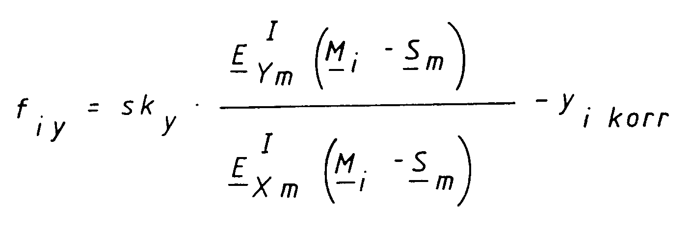

Die angenommene Lage (Position S m und Orientierung R m) des Sensors 34 bzw. 36 entspricht im allgemeinen zunächst nicht der wahren Lage. Es treten die genannten Fehlervektoren auf. Im vorliegenden Fall hat der gesuchte Vektor v sechs Komponenten. Die Fehlervektoren liefern insgesamt zehn Fehler. Es gilt nun, die Komponenten des Vektors v, also z.B. für Sensor 36 die Koordinaten xI2, yI2, zI2 und die Euler-Winkel ψ, ϑ, ρ gezielt so zu variieren, dass die Fehler verschwinden. Das kann mittels der bekannten Newtonschen Iteration geschehen.For each sensor there are 34 and 36 error vectors with the components:
The assumed position (position S m and orientation R m ) of the
Es wird aus den Fehlervektoren eine Fehlerfunktion
gebildet. Diese Fehlerfunktion soll minimiert werden. Das entspricht einem "Least-Square-Fit".The error vectors become an error function
educated. This error function should be minimized. This corresponds to a "least square fit".
Für das gesuchte Minimum gilt:
![]()
wobei O der Nullvektor ist. Die Komponenten der Fehlervektoren fiy und fiz hängen jede von allen Komponenten des Vektors S nach bekannten Funktionen ab. Es können daher die partiellen Ableitungen
gebildet werden,wobei vl die l-te Komponente des Vektors v ist. Es ist also etwa für Sensor 36 ![]()
![]()
Darin sind v (n+1) und v (n) die sich aus dem (n+1)ten oder n-ten Iterationsschritt ergebenden Näherungen für den Vektor v. DT ist die transponierte Jacobi-Matrix D, also eine Matrix, bei welcher gegenüber der Matrix D Zeilen und Spalten vertauscht sind. Das Zeichen ⁻¹ bedeutet die inverse Matrix. Und f (n) ist der Fehlervektor nach dem n-ten Iterationsschritt.For the minimum searched, the following applies:
![]()
where O is the zero vector. The components of the error vectors f iy and f iz each depend on all components of the vector S according to known functions. It can therefore be the partial derivatives
are formed, where v l is the lth component of the vector v . So it's about ![]()
![]()
Here v (n + 1) and v (n) are the approximations for the vector v resulting from the (n + 1) th or nth iteration step. D T is the transposed Jacobi matrix D, i.e. a matrix in which rows and columns are interchanged with the matrix D. The sign ⁻¹ means the inverse matrix. And f (n) is the error vector after the nth iteration step.
Die Iteration wird fortgesetzt, bis der Fehlervektor f (n) einen vorgegebenen Schwellwert unterschreitet. Dann ist die Lage des betreffenden Sensors 34 oder 36 hinreichend genau bekannt. Das beschriebene Verfahren wird für die beiden Sensoren 34 und 36 getrennt durchgeführt.The iteration continues until the error vector f (n) falls below a predetermined threshold value. Then the position of the
Die erhaltenen Daten über die Lage der Sensoren 34 und 36 werden gespeichert. Diese Daten werden anschliessend für die Positionierung von Patienten benutzt. Die Bestimmung der Lage der Sensoren wird in regelmässigen Zeitabständen, z.B. täglich, wiederholt.The data obtained about the position of the
Bei der Positionierung eines Patienten sind z.B. an dem Kopf des Patienten vier kugelförmige Markierungen 22, 24, 26, 28 in definierter Lage angebracht. Bei der ersten Vermessung ist der Kopf des Patienten, wie beschrieben, mittels stereotaktischer Verfahren in eine solche Lage gebracht, dass sich ein zu bestrahlender Tumor genau in dem Isozentrum 20 befindet. In dieser Lage werden die vier Markierungen 22, 24, 26 und 28 durch die beiden Sensoren 34 und 36 vermessen.When positioning a patient, for example, four
Zu diesem Zweck werden ähnlich wie bei den Markierungen 145, 146, 148, 150 und 152 des Referenzkörpers 144 zunächst die Schwerpunkte der Bilder dieser Markierungen 22, 24, 26 und 28 bestimmt. Diese Schwerpunkte werden nach Massgabe der inneren Kamera-Parameter (Fig. 7) korrigiert, wie dies oben im Zusammenhang mit den Markierungen 145, 146, 148, 150 und 152 des Referenzkörpers schon beschrieben wurde. Zu jedem der so bestimmten, korrigierten Schwerpunkte gehört ein "Sehstrahl", der von diesem Schwerpunkt durch den Hauptpunkt 134 des Objektivs 112 verläuft. Dieser Sehstrahl sollte durch den Mittelpunkt der Markierung hindurchgehen.For this purpose, similarly to the
Zunächst wird für jede der Markierungen 22, 24, 26 und 28 unabhängig die absolute Position im Raum in dem ortsfesten Koordinatensystem xI, yI, zI bestimmt. Zu diesem Zweck wird zunächst ein Startwert ermittelt als "Schnittpunkt" der von den beiden Sensoren 34 und 36 auf ein und dieselbe Markierung gerichteten Sehstrahlen. Aufgrund von Messungenauigkeiten haben die Sehstrahlen im Raum im allgemeinen keinen exakten Schnittpunkt. Daher wird als "Schnittpunkt" jeweils der Mittelpunkt der Abstandsstrecke zwischen den Sehstrahlen gewählt.First, the absolute position in space in the fixed coordinate system x I , y I , z I is determined independently for each of the
Es wird nun wieder ausgehend von den Startwerten die genaue Position der Markierungen 22, 24, 26 und 28 im ortsfesten Koordinatensystem xI, yI, zI für jede Markierung einzeln mittels einer Newton-Iteration bestimmt. Der als Schnittpunkt der Sehstrahlen geschätzte Positionsvektor P j der j-ten Markierung 22, 24, 26 oder 28 (j = 1...4) im Koordinatensystem xI, yI, zI ist
![]()
The exact position of the
![]()
Es ergeben sich dann im sensorfesten Koordinatensystem für den ersten Sensor 34 (m=1) die Fehler, also Abweichungen zwischen berechneter und beobachteter Lage des Bildes der Markierung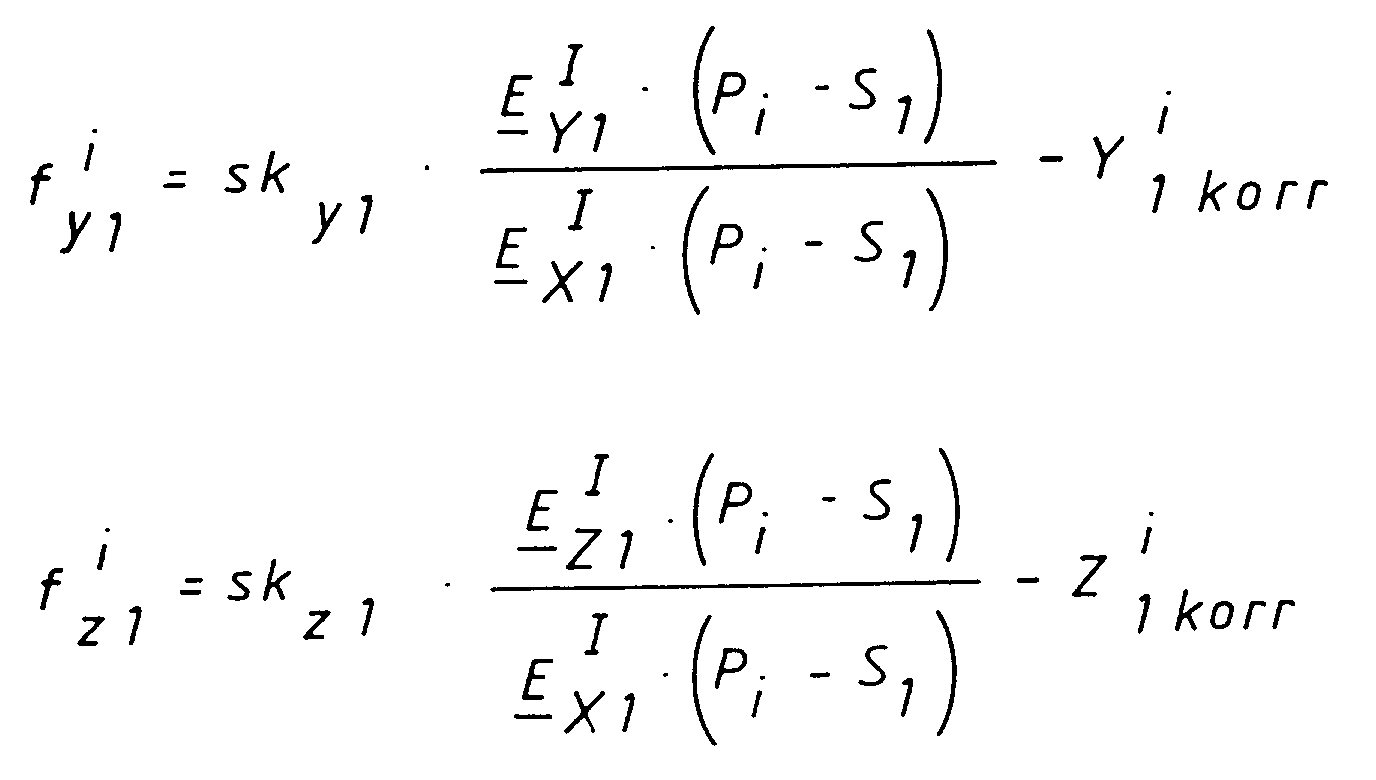
Ebenso ergeben sich im sensorfesten Koordinatensystem für den zweiten Sensor (m=2) die Fehler
Dabei sind - ähnlich wie bei der Messung der Lage der Sensoren 34 und 36 mittels des Testkörpers 144 - S₁ und S₂ Lagevektoren der Sensoren 34 bzw. 36 und ymkorr und zmkorr die beobachteten und hinsichtlich der inneren Kamera-Parameter korrigierten Koordinaten der Bilder der Markierungen 145 bis 152 im sensorfesten Koordinatensystem. Die Fehler sind wieder bekannte Funktionen der geschätzten Positionskoordinaten xj, yj, und zj (P1,P2,P₃). Die Fehler können für jede der Markierungen zu einem Fehlervektor
zusammengefasst werden. Es kann dann eine Jacobi-Matrix D* mit den Elemten
gebildet werden. Die Jacobi-Matrix ist hier eine 4x3-Matrix.The errors then arise in the sensor-fixed coordinate system for the first sensor 34 (m = 1), that is to say deviations between the calculated and observed position of the image of the marking
The errors also result in the sensor-fixed coordinate system for the second sensor (m = 2)
Here - similar to the measurement of the position of the
be summarized. A Jacobi matrix D * with the elements can then be used
be formed. The Jacobi matrix is a 4x3 matrix here.
Mit einer Newtonschen Iteration
![]()
ergeben sich die Ortsvektoren der Markierungen 22, 24, 26 und 28 in dem ortsfesten Koordinatensystem xI, yI, xI.With a Newtonian iteration
![]()
the location vectors of the
Aus den so erhaltenen Positionen der vier Markierungen 22, 24, 26, 28 wird ein "Eigenkoordinatensystem" xE, yE, zE definiert. Der Ursprung dieses Eigenkoordinatensystems liegt im Schwerpunkt 30 der vier Markierungen 22, 24, 26 und 28. Der in zE-Richtung zeigende Einheitsvektor ist das normierte Vektorprodukt der beiden Vektoren 154 und 156, welche die Schwerpunkte der Markierungen 24 und 26 bzw. 28 und 22 miteinander verbinden (Fig. 9). Dieser Einheitsvektor und die zE-Achse stehen somit senkrecht auf der Papierebene von Fig. 9 und sind in diese Papierebene hinein gerichtet. Der in Richtung der yE-Achse zeigende Einheitsvektor läuft parallel zu der Verbindungslinie 158 zwischen den Schwerpunkten der Markierungen 22 und 28. Die yE-Achse zeigt dabei nach links in Fig. 9. Der in Richtung der xE-Achse zeigende Einheitsvektor bildet mit den Einheitsvektoren der yE- und zE-Achsen ein Rechtssystem und zeigt nach unten in Fig. 9.A "self-coordinate system" x E , y E , z E is defined from the positions of the four
Die so erhaltenen Daten P j werden gespeichert. Wenn sich die Markierungen 22, 24, 26 und 28 in dieser Position befinden, dann befindet sich der Tumor genau im Isozentrum 20.The data P j thus obtained are stored. If the
Bei einer nachfolgenden Bestrahlung liegen die bei stereotaktischer Ausrichtung des Kopfes einmal gespeicherten Koordinaten der Markierungen 22, 24, 26 und 28 vor. Es muss jetzt die Lage des Kopfes relativ zu diesen festen Koordinaten laufend bestimmt werden. Dies geschieht wieder mittels einer Newtonschen Iteration.In the case of a subsequent irradiation, the coordinates of the
In diesem Fall ist ein Vektor
![]()
gesucht. Komponenten dieses Vektors sind die Abweichungen der Lage des kopffesten, durch die Markierungen 22, 24, 26 und 28 bestimmten Eigenkoordinatensystems von der Lage, die in der oben beschriebenen Weise bestimmt und gespeichert wurde und bei welcher der Kopf des Patienten in der durch stereotaktische Methoden festgelegten Lage mit dem Tumor im Isozentrum 20 gehalten wurde.In this case it is a vector
![]()
searched. Components of this vector are the deviations of the position of the head-fixed self-coordinate system, determined by the
Man kann die Position des Kopfes bzw. des kopffesten Eigenkoordinatensystems durch einen Translationsvektor t = (Δxk, Δyk, Δzk) angeben. Die Orientierung des Kopfes bzw. des kopffesten Eigenkoordinatensystems xE, yE, zE relativ zu dem ortsfesten Koordinatensystem xI, yI, zI kann durch eine Richtungskosinusmatrix Rk als Funktion der Euler-Winkel Δψk, Δϑk, Δρk angegeben werden. Es ist wieder
![]()
analog zu der oben angegebenen Richtungskosinusmatrix für die Festlegung der Orientierung des Sensors 36.The position of the head or the head-fixed self-coordinate system can be specified by a translation vector t = (Δx k , Δy k , Δz k ). The orientation of the head or the head-fixed coordinate system x E , y E , z E relative to the stationary coordinate system x I , y I , z I can be determined by a direction cosine matrix R k as a function of the Euler angles Δψ k , Δϑ k , Δρ k can be specified. It is again
![]()
analogous to the direction cosine matrix given above for determining the orientation of the
Für die Fehler in den sensorfesten Koordinatensystemen ergibt sich für die vier Markierungen 22, 24, 26 und 28 (j = 1...4) für den Sensor 34 (m = 1)
Für den Sensor 36 (m = 2) ergibt sich dementsprechend:
Darin stellt Rk P j den um die Winkel Δψk, Δϑk, Δρk gedrehten Ortsvektor der j-ten Markierung (22, 24, 26 oder 28) dar. Dem so verdrehten Ortsvektor ist noch die Translation t überlagert. Es ergibt sich daraus mit einer geschätzten Richtungskosinusmatrix und einem geschätzten Translationsvektor t ein Schätzwert für die Lage jeder der Markierungen 22, 24, 26 oder 28. Die Differenz mit dem Vektor S₁ oder S₂ ergibt den Vektor von dem Hauptpunkt 134 des Objektivs 112 zu der Markierung "j", also 22, 24, 26 oder 28. Dieser Differenzvektor wird mit den Einheitsvektoren E ym bzw. E zm und dem Einheitsvektor E xm skalar multipliziert. Die Verhältnisse liefern Winkel, die mit einem Skalenfaktor skym bzw. skzm die berechneten Koordinaten der Bilder der Markierungen 22, 24, 26 oder 28 auf der Anordnung 116 von Sensorelementen in dem sensorfesten Koordinatensystem liefert. Die Differenz zu den tatsächlich beobachteten Bildern (mit Korrektur hinsichtlich der inneren Kamera-Parameter) liefern die Fehler.For the errors in the sensor-fixed coordinate systems, the four
Accordingly, for sensor 36 (m = 2):
In it, R k P j represents the location vector of the j-th mark (22, 24, 26 or 28) rotated by the angles Δψ k , Δϑ k , Δρ k . The translation t is also superimposed on the location vector thus rotated. With an estimated direction cosine matrix and an estimated translation vector t , this results in an estimate for the position of each of the
Der Fehlervektor f hat bei zwei Sensoren 34 und 36 (m=1;2) und vier Markierungen 22, 24, 26, 28 (j = 1...4) mit je zwei Koordinaten sechzehn Komponenten. Die sechzehn Komponenten des Fehlervektors f sind bekannte Funktionen der sechs Komponeten des Vektors k. Man kann wieder eine Jacobi-Matrix D' aus den partiellen Ableitungen der Komponenten des Fehlervektors f nach jeweils einer Komponente des Vektors k bilden. Eine solche Jacobi-Matrix ist eine 16 x 6 - Matrix.With two
Es werden nun zunächst zur Durchführung der Newtonschen Iteration als Schnitt zweier Sehstrahlen Schätzwerte für die Positionen der Markierungen 22, 24, 26 und 28 ermittelt. Aus diesen Schätzwerten ergeben sich Ursprung und Koordinatenrichtungen des Eigenkoordinatensystems xE, yE, zE der Markierungen 22, 24, 26 und 28. Aus diesem so ermittelten, aktuellen Eigenkoordinatensystem und dem in der Ursprungslage bestimmten, gespeicherten Eigenkoordinatensystem werden Rotation und Translation der Lageänderung ermittelt, also die Abbildung, welche das Eigenkoordinatensystem der Ausgangslage auf das aktuelle Eigenkoordinatensystem abbildet. Das liefert als Startwerte Komponenten des Vektors k.Estimates for the positions of the
Es werden dann ausgehend von den Startwerten des Vektors k mittels der oben beschriebenen Newtonschen Iteration die tatsächlichen Komponenten des Vektors k berechnet.The actual components of the vector k are then calculated from the starting values of the vector k using the Newtonian iteration described above.
Die vorstehend beschriebenen Operationen werden zyklisch wiederholt, so dass ständig der aktuelle Vektor k zur Verfügung steht. Dabei bildet dann das Resultat jedes Zyklus die Startwerte für den nächstfolgenden Zyklus.The operations described above are repeated cyclically so that the current vector k is constantly available. The result of each cycle then forms the start values for the next cycle.
Wie in Fig.1 schematisch dargestellt ist, liegt der Patient auf einem Schlitten 15, der in waagerechter Längsrichtung auf einem Bestrahlungstisch 16 verschiebbar geführt ist. Der Kopf des Patienten liegt auf einer Kopfauflage 108. Die Kopfauflage 108 ist relativ zu dem Schlitten in Vertikal- und in Querrichtung beweglich. In Querrichtung ist die Kopfauflage 108 durch ein Stellglied 160 verstellbar. In Vertikalrichtung ist die Kopfauflage 108 durch ein Stellglied 162 verstellbar. Eine Verstellung der Kopfauflage 108 in Längsrichtung relativ zu dem Schlitten 15 oder Bestrahlungstisch 16 ist nicht vorgesehen, da dann der Hals des Patienten bei einer Verstellung gedehnt oder gestaucht werden müßte. Stattdessen erfolgt in Längsrichtung eine Verstellung des Schlittens 15 durch ein Stellglied 164. Der Kopf des Patienten kann mit üblichen Mitteln auf der Kopfauflage 108 fixiert sein. Eventuelle Bewegungen werden aber durch die Regelkreise herausgeregelt. Der "Tumorpunkt" im Kopf des Patienten bleibt mit hoher Genauigkeit im Isozentrum 20.As is shown schematically in FIG. 1, the patient lies on a
Die beschriebene Anordnung kann in verschiedener Weise abgewandelt werden. Statt zweier Sensoren 34 und 36 können drei Sensoren vorgesehen werden. Bei Überbestimmung können dann die Koordinaten aus den berechneten Strahlen 44,46.. nach der Methode der kleinsten Fehlerquadrate berechnet werden.The arrangement described can be modified in various ways. Instead of two
Claims (13)
gekennzeichnet durch
marked by
gekennzeichnet durch
marked by
gekennzeichnet durch die Verfahrensschritte:
characterized by the process steps:
Applications Claiming Priority (2)
| Application Number | Priority Date | Filing Date | Title |
|---|---|---|---|
| DE4207632A DE4207632C2 (en) | 1992-03-11 | 1992-03-11 | Device and method for positioning a body part for treatment purposes |
| DE4207632 | 1992-03-11 |
Publications (2)
| Publication Number | Publication Date |
|---|---|
| EP0560331A1 true EP0560331A1 (en) | 1993-09-15 |
| EP0560331B1 EP0560331B1 (en) | 1999-02-17 |
Family
ID=6453718
Family Applications (1)
| Application Number | Title | Priority Date | Filing Date |
|---|---|---|---|
| EP93103855A Expired - Lifetime EP0560331B1 (en) | 1992-03-11 | 1993-03-10 | Device and method for positioning a part of the body for therapeutic treatment |
Country Status (6)
| Country | Link |
|---|---|
| US (1) | US5315630A (en) |
| EP (1) | EP0560331B1 (en) |
| JP (1) | JPH067335A (en) |
| CN (1) | CN1076791A (en) |
| AT (1) | ATE176750T1 (en) |
| DE (2) | DE4207632C2 (en) |
Cited By (10)
| Publication number | Priority date | Publication date | Assignee | Title |
|---|---|---|---|---|
| US5446548A (en) * | 1993-10-08 | 1995-08-29 | Siemens Medical Systems, Inc. | Patient positioning and monitoring system |
| EP0804943A2 (en) * | 1996-05-03 | 1997-11-05 | Siemens Medical Systems, Inc. | System and method for verifying the amount of radiation delivered to an object |
| WO1998017349A1 (en) * | 1996-10-24 | 1998-04-30 | Nomos Corporation | Planning method and apparatus for radiation dosimetry |
| FR2765009A1 (en) * | 1997-06-23 | 1998-12-24 | Ch & U Lille | Automatic configuration of stereotactic radio surgical helmet |
| EP0910989A1 (en) * | 1997-10-17 | 1999-04-28 | Siemens Aktiengesellschaft | Radiographic apparatus |
| WO1999040846A1 (en) * | 1998-02-13 | 1999-08-19 | Mueller Reinhold G | Reproducible position or location identification of deformable bodies |
| US6393096B1 (en) | 1998-05-27 | 2002-05-21 | Nomos Corporation | Planning method and apparatus for radiation dosimetry |
| WO2007072356A2 (en) * | 2005-12-21 | 2007-06-28 | Koninkijke Philips Electronics N.V. | Positioning system for patient monitoring sensors |
| DE19639615C5 (en) * | 1996-09-26 | 2008-11-06 | Brainlab Ag | Reflector referencing system for surgical and medical instruments |
| DE102008062030A1 (en) * | 2008-12-12 | 2010-06-17 | Siemens Aktiengesellschaft | Arrangement and method for positioning objects to be imaged |
Families Citing this family (134)
| Publication number | Priority date | Publication date | Assignee | Title |
|---|---|---|---|---|
| US6331180B1 (en) | 1988-05-03 | 2001-12-18 | Sherwood Services Ag | Target-centered stereotaxtic surgical arc system with reorientatable arc axis |
| FR2652928B1 (en) | 1989-10-05 | 1994-07-29 | Diadix Sa | INTERACTIVE LOCAL INTERVENTION SYSTEM WITHIN A AREA OF A NON-HOMOGENEOUS STRUCTURE. |
| US6405072B1 (en) | 1991-01-28 | 2002-06-11 | Sherwood Services Ag | Apparatus and method for determining a location of an anatomical target with reference to a medical apparatus |
| US6006126A (en) | 1991-01-28 | 1999-12-21 | Cosman; Eric R. | System and method for stereotactic registration of image scan data |
| US5603318A (en) | 1992-04-21 | 1997-02-18 | University Of Utah Research Foundation | Apparatus and method for photogrammetric surgical localization |
| WO1994004938A1 (en) | 1992-08-14 | 1994-03-03 | British Telecommunications Public Limited Company | Position location system |
| US5541856A (en) * | 1993-11-08 | 1996-07-30 | Imaging Systems International | X-ray inspection system |
| DE69531994T2 (en) | 1994-09-15 | 2004-07-22 | OEC Medical Systems, Inc., Boston | SYSTEM FOR POSITION DETECTION BY MEANS OF A REFERENCE UNIT ATTACHED TO A PATIENT'S HEAD FOR USE IN THE MEDICAL AREA |
| US5622187A (en) * | 1994-09-30 | 1997-04-22 | Nomos Corporation | Method and apparatus for patient positioning for radiation therapy |
| DE19506197A1 (en) * | 1995-02-23 | 1996-09-05 | Aesculap Ag | Method and device for determining the location of a body part |
| DE19508228B4 (en) * | 1995-03-08 | 2005-12-29 | Brainlab Ag | Method for irradiating a target point located in a target object |
| DE19515748A1 (en) * | 1995-04-28 | 1996-10-31 | Siemens Ag | Device for treatment with acoustic waves |
| ES2136808T3 (en) * | 1995-06-07 | 1999-12-01 | Inductotherm Corp | VIDEO POSITIONING SYSTEM FOR A SPILL CONTAINER. |
| US5592939A (en) | 1995-06-14 | 1997-01-14 | Martinelli; Michael A. | Method and system for navigating a catheter probe |
| DE19530013C1 (en) * | 1995-08-16 | 1997-03-06 | Werner Dipl Phys Brenneisen | Correcting position of target e.g. tumour in target region of radiation treatment device |
| US6351659B1 (en) * | 1995-09-28 | 2002-02-26 | Brainlab Med. Computersysteme Gmbh | Neuro-navigation system |
| CN1051724C (en) * | 1995-09-28 | 2000-04-26 | 深圳奥沃国际科技发展有限公司 | Stereo directional radiotherapy apparatus |
| DE19614643A1 (en) * | 1996-04-13 | 1997-10-16 | Werner Dipl Phys Brenneisen | Stereotaxial targetted irradiation process for brain tumours |
| US5820553A (en) * | 1996-08-16 | 1998-10-13 | Siemens Medical Systems, Inc. | Identification system and method for radiation therapy |
| US5745545A (en) * | 1996-08-16 | 1998-04-28 | Siemens Medical Systems, Inc. | Alignment system and method for intra-operative radiation therapy |
| US5784431A (en) * | 1996-10-29 | 1998-07-21 | University Of Pittsburgh Of The Commonwealth System Of Higher Education | Apparatus for matching X-ray images with reference images |
| US6226548B1 (en) | 1997-09-24 | 2001-05-01 | Surgical Navigation Technologies, Inc. | Percutaneous registration apparatus and method for use in computer-assisted surgical navigation |
| US5923727A (en) * | 1997-09-30 | 1999-07-13 | Siemens Corporate Research, Inc. | Method and apparatus for calibrating an intra-operative X-ray system |
| US6021343A (en) | 1997-11-20 | 2000-02-01 | Surgical Navigation Technologies | Image guided awl/tap/screwdriver |
| US6348058B1 (en) | 1997-12-12 | 2002-02-19 | Surgical Navigation Technologies, Inc. | Image guided spinal surgery guide, system, and method for use thereof |
| DE69937286D1 (en) * | 1998-01-14 | 2007-11-22 | Leonard Reiffel | ARRANGEMENT FOR STABILIZING BODY INTERNAL RADIATION GROUNDING SURFACES |
| US6118845A (en) | 1998-06-29 | 2000-09-12 | Surgical Navigation Technologies, Inc. | System and methods for the reduction and elimination of image artifacts in the calibration of X-ray imagers |
| US6477400B1 (en) | 1998-08-20 | 2002-11-05 | Sofamor Danek Holdings, Inc. | Fluoroscopic image guided orthopaedic surgery system with intraoperative registration |
| DE19841859A1 (en) * | 1998-09-14 | 2000-04-06 | Deutsches Krebsforsch | Method of positioning a body part for treatment on a medical device |
| US6937696B1 (en) | 1998-10-23 | 2005-08-30 | Varian Medical Systems Technologies, Inc. | Method and system for predictive physiological gating |
| US6973202B2 (en) | 1998-10-23 | 2005-12-06 | Varian Medical Systems Technologies, Inc. | Single-camera tracking of an object |
| US7158610B2 (en) * | 2003-09-05 | 2007-01-02 | Varian Medical Systems Technologies, Inc. | Systems and methods for processing x-ray images |
| US6621889B1 (en) | 1998-10-23 | 2003-09-16 | Varian Medical Systems, Inc. | Method and system for predictive physiological gating of radiation therapy |
| CA2347944A1 (en) | 1998-10-23 | 2000-05-04 | Varian Medical Systems, Inc. | Method and system for physiological gating of radiation therapy |
| US6279579B1 (en) | 1998-10-23 | 2001-08-28 | Varian Medical Systems, Inc. | Method and system for positioning patients for medical treatment procedures |
| US6980679B2 (en) * | 1998-10-23 | 2005-12-27 | Varian Medical System Technologies, Inc. | Method and system for monitoring breathing activity of a subject |
| JP4101951B2 (en) | 1998-11-10 | 2008-06-18 | オリンパス株式会社 | Surgical microscope |
| US6138302A (en) * | 1998-11-10 | 2000-10-31 | University Of Pittsburgh Of The Commonwealth System Of Higher Education | Apparatus and method for positioning patient |
| US6720988B1 (en) * | 1998-12-08 | 2004-04-13 | Intuitive Surgical, Inc. | Stereo imaging system and method for use in telerobotic systems |
| DE19908844C2 (en) * | 1999-03-01 | 2001-06-07 | Aesculap Ag & Co Kg | Method and device for correlating the actual position of a marking element with the position data obtained by an imaging method |
| DE19908903C2 (en) | 1999-03-02 | 2001-04-26 | Deutsches Krebsforsch | Localization unit for imaging and positioning devices, their use and adapter module |
| US6470207B1 (en) | 1999-03-23 | 2002-10-22 | Surgical Navigation Technologies, Inc. | Navigational guidance via computer-assisted fluoroscopic imaging |
| DE19915720A1 (en) * | 1999-04-08 | 2000-11-16 | Deutsches Krebsforsch | Stereotactic localization method and measurement phantom for medical use |
| US6491699B1 (en) | 1999-04-20 | 2002-12-10 | Surgical Navigation Technologies, Inc. | Instrument guidance method and system for image guided surgery |
| DE19917867B4 (en) * | 1999-04-20 | 2005-04-21 | Brainlab Ag | Method and device for image support in the treatment of treatment objectives with integration of X-ray detection and navigation system |
| US6711433B1 (en) | 1999-09-30 | 2004-03-23 | Siemens Corporate Research, Inc. | Method for providing a virtual contrast agent for augmented angioscopy |
| US8239001B2 (en) | 2003-10-17 | 2012-08-07 | Medtronic Navigation, Inc. | Method and apparatus for surgical navigation |
| US6381485B1 (en) | 1999-10-28 | 2002-04-30 | Surgical Navigation Technologies, Inc. | Registration of human anatomy integrated for electromagnetic localization |
| US6747539B1 (en) | 1999-10-28 | 2004-06-08 | Michael A. Martinelli | Patient-shielding and coil system |
| US8644907B2 (en) | 1999-10-28 | 2014-02-04 | Medtronic Navigaton, Inc. | Method and apparatus for surgical navigation |
| US6235038B1 (en) | 1999-10-28 | 2001-05-22 | Medtronic Surgical Navigation Technologies | System for translation of electromagnetic and optical localization systems |
| US7366562B2 (en) | 2003-10-17 | 2008-04-29 | Medtronic Navigation, Inc. | Method and apparatus for surgical navigation |
| US11331150B2 (en) | 1999-10-28 | 2022-05-17 | Medtronic Navigation, Inc. | Method and apparatus for surgical navigation |
| US6499488B1 (en) | 1999-10-28 | 2002-12-31 | Winchester Development Associates | Surgical sensor |
| US6493573B1 (en) | 1999-10-28 | 2002-12-10 | Winchester Development Associates | Method and system for navigating a catheter probe in the presence of field-influencing objects |
| WO2001031466A1 (en) | 1999-10-28 | 2001-05-03 | Winchester Development Associates | Coil structures and methods for generating magnetic fields |
| US6474341B1 (en) | 1999-10-28 | 2002-11-05 | Surgical Navigation Technologies, Inc. | Surgical communication and power system |
| US20030206614A1 (en) * | 2000-01-31 | 2003-11-06 | Kendrick Lance A. | Method and apparatus for alignment of medical radiation beams using a body frame |
| US6725080B2 (en) | 2000-03-01 | 2004-04-20 | Surgical Navigation Technologies, Inc. | Multiple cannula image guided tool for image guided procedures |
| US6535756B1 (en) | 2000-04-07 | 2003-03-18 | Surgical Navigation Technologies, Inc. | Trajectory storage apparatus and method for surgical navigation system |
| US7085400B1 (en) | 2000-06-14 | 2006-08-01 | Surgical Navigation Technologies, Inc. | System and method for image based sensor calibration |
| DE10051370A1 (en) * | 2000-10-17 | 2002-05-02 | Brainlab Ag | Method and appliance for exact positioning of patient for radiation therapy and radio surgery with which only one camera is used to determine and compensate for positional error |
| US6636757B1 (en) | 2001-06-04 | 2003-10-21 | Surgical Navigation Technologies, Inc. | Method and apparatus for electromagnetic navigation of a surgical probe near a metal object |
| US7769430B2 (en) * | 2001-06-26 | 2010-08-03 | Varian Medical Systems, Inc. | Patient visual instruction techniques for synchronizing breathing with a medical procedure |
| DE10161152B4 (en) * | 2001-12-12 | 2014-02-13 | Medical Intelligence Medizintechnik Gmbh | Positioning the treatment beam of a radiation therapy system by means of a hexapod |
| US7016522B2 (en) * | 2002-01-15 | 2006-03-21 | Siemens Medical Solutions Usa, Inc. | Patient positioning by video imaging |
| US6947786B2 (en) | 2002-02-28 | 2005-09-20 | Surgical Navigation Technologies, Inc. | Method and apparatus for perspective inversion |
| US6990368B2 (en) | 2002-04-04 | 2006-01-24 | Surgical Navigation Technologies, Inc. | Method and apparatus for virtual digital subtraction angiography |
| US7998062B2 (en) | 2004-03-29 | 2011-08-16 | Superdimension, Ltd. | Endoscope structures and techniques for navigating to a target in branched structure |
| US7620444B2 (en) * | 2002-10-05 | 2009-11-17 | General Electric Company | Systems and methods for improving usability of images for medical applications |
| US7366333B2 (en) * | 2002-11-11 | 2008-04-29 | Art, Advanced Research Technologies, Inc. | Method and apparatus for selecting regions of interest in optical imaging |
| US7599730B2 (en) | 2002-11-19 | 2009-10-06 | Medtronic Navigation, Inc. | Navigation system for cardiac therapies |
| US7697972B2 (en) | 2002-11-19 | 2010-04-13 | Medtronic Navigation, Inc. | Navigation system for cardiac therapies |
| US7660623B2 (en) | 2003-01-30 | 2010-02-09 | Medtronic Navigation, Inc. | Six degree of freedom alignment display for medical procedures |
| US7542791B2 (en) | 2003-01-30 | 2009-06-02 | Medtronic Navigation, Inc. | Method and apparatus for preplanning a surgical procedure |
| EP1653853B1 (en) * | 2003-08-08 | 2015-10-14 | Koninklijke Philips N.V. | Using magnetic resonance images for locating anatomical targets |
| US7313430B2 (en) * | 2003-08-28 | 2007-12-25 | Medtronic Navigation, Inc. | Method and apparatus for performing stereotactic surgery |
| US8571639B2 (en) * | 2003-09-05 | 2013-10-29 | Varian Medical Systems, Inc. | Systems and methods for gating medical procedures |
| US20050053267A1 (en) * | 2003-09-05 | 2005-03-10 | Varian Medical Systems Technologies, Inc. | Systems and methods for tracking moving targets and monitoring object positions |
| EP2316328B1 (en) | 2003-09-15 | 2012-05-09 | Super Dimension Ltd. | Wrap-around holding device for use with bronchoscopes |
| ATE438335T1 (en) | 2003-09-15 | 2009-08-15 | Super Dimension Ltd | SYSTEM OF ACCESSORIES FOR USE WITH BRONCHOSCOPES |
| US7835778B2 (en) | 2003-10-16 | 2010-11-16 | Medtronic Navigation, Inc. | Method and apparatus for surgical navigation of a multiple piece construct for implantation |
| US7840253B2 (en) | 2003-10-17 | 2010-11-23 | Medtronic Navigation, Inc. | Method and apparatus for surgical navigation |
| US8764725B2 (en) | 2004-02-09 | 2014-07-01 | Covidien Lp | Directional anchoring mechanism, method and applications thereof |
| US7567834B2 (en) | 2004-05-03 | 2009-07-28 | Medtronic Navigation, Inc. | Method and apparatus for implantation between two vertebral bodies |
| GB2418495B (en) * | 2004-09-24 | 2010-04-28 | Vision Rt Ltd | Image processing system for use with a patient positioning device |
| US20060074305A1 (en) * | 2004-09-30 | 2006-04-06 | Varian Medical Systems Technologies, Inc. | Patient multimedia display |
| US9119541B2 (en) * | 2005-08-30 | 2015-09-01 | Varian Medical Systems, Inc. | Eyewear for patient prompting |
| US7835784B2 (en) | 2005-09-21 | 2010-11-16 | Medtronic Navigation, Inc. | Method and apparatus for positioning a reference frame |
| US9168102B2 (en) | 2006-01-18 | 2015-10-27 | Medtronic Navigation, Inc. | Method and apparatus for providing a container to a sterile environment |
| US8112292B2 (en) | 2006-04-21 | 2012-02-07 | Medtronic Navigation, Inc. | Method and apparatus for optimizing a therapy |
| US20090209846A1 (en) * | 2006-06-28 | 2009-08-20 | Roland Bammer | Apparatus and method for real-time motion-compensated magnetic resonance imaging |
| US8660635B2 (en) | 2006-09-29 | 2014-02-25 | Medtronic, Inc. | Method and apparatus for optimizing a computer assisted surgical procedure |
| US7953247B2 (en) | 2007-05-21 | 2011-05-31 | Snap-On Incorporated | Method and apparatus for wheel alignment |
| WO2009021447A1 (en) * | 2007-08-10 | 2009-02-19 | Chunhui Wu | A method and an equipment of human body's center of gravity in x light image formation real-time demarcation. |
| US8905920B2 (en) | 2007-09-27 | 2014-12-09 | Covidien Lp | Bronchoscope adapter and method |
| EP2211721B1 (en) | 2007-11-19 | 2019-07-10 | Pyronia Medical Technologies, Inc. | Patient positioning system and methods for diagnostic radiology and radiotherapy |
| US9575140B2 (en) | 2008-04-03 | 2017-02-21 | Covidien Lp | Magnetic interference detection system and method |
| US8473032B2 (en) | 2008-06-03 | 2013-06-25 | Superdimension, Ltd. | Feature-based registration method |
| US8218847B2 (en) | 2008-06-06 | 2012-07-10 | Superdimension, Ltd. | Hybrid registration method |
| US7938709B2 (en) * | 2008-06-26 | 2011-05-10 | Vladimir Leonov | Steering mechanism for a toy vehicle |
| DE102008032295B4 (en) * | 2008-07-09 | 2014-12-24 | Siemens Aktiengesellschaft | X-ray equipment |
| US8932207B2 (en) | 2008-07-10 | 2015-01-13 | Covidien Lp | Integrated multi-functional endoscopic tool |
| US20100061596A1 (en) * | 2008-09-05 | 2010-03-11 | Varian Medical Systems Technologies, Inc. | Video-Based Breathing Monitoring Without Fiducial Tracking |
| US10667727B2 (en) * | 2008-09-05 | 2020-06-02 | Varian Medical Systems, Inc. | Systems and methods for determining a state of a patient |
| US8165658B2 (en) | 2008-09-26 | 2012-04-24 | Medtronic, Inc. | Method and apparatus for positioning a guide relative to a base |
| US8175681B2 (en) | 2008-12-16 | 2012-05-08 | Medtronic Navigation Inc. | Combination of electromagnetic and electropotential localization |
| US8611984B2 (en) | 2009-04-08 | 2013-12-17 | Covidien Lp | Locatable catheter |
| US8494613B2 (en) | 2009-08-31 | 2013-07-23 | Medtronic, Inc. | Combination localization system |
| US8494614B2 (en) | 2009-08-31 | 2013-07-23 | Regents Of The University Of Minnesota | Combination localization system |
| GB201007580D0 (en) | 2010-05-06 | 2010-06-23 | Im Sense Ltd | Making robust images |
| US10582834B2 (en) | 2010-06-15 | 2020-03-10 | Covidien Lp | Locatable expandable working channel and method |
| RU2567265C2 (en) * | 2010-12-21 | 2015-11-10 | Конинклейке Филипс Электроникс Н.В. | Light therapy device |
| DE102011050201A1 (en) * | 2011-05-07 | 2012-11-08 | Benedikt Hieronimi | System for the evaluation of identification marks, identification marks and their use |
| US20150025548A1 (en) | 2012-03-08 | 2015-01-22 | Neutar, Llc | Patient and Procedure Customized Fixation and Targeting Devices for Stereotactic Frames |
| US9200899B2 (en) | 2012-03-22 | 2015-12-01 | Virtek Vision International, Inc. | Laser projection system and method |
| US9788810B2 (en) * | 2015-06-25 | 2017-10-17 | Portavision Medical Llc | System and method for X-ray imaging alignment |
| US10952593B2 (en) | 2014-06-10 | 2021-03-23 | Covidien Lp | Bronchoscope adapter |
| US10426555B2 (en) | 2015-06-03 | 2019-10-01 | Covidien Lp | Medical instrument with sensor for use in a system and method for electromagnetic navigation |
| US9962134B2 (en) | 2015-10-28 | 2018-05-08 | Medtronic Navigation, Inc. | Apparatus and method for maintaining image quality while minimizing X-ray dosage of a patient |
| US10478254B2 (en) | 2016-05-16 | 2019-11-19 | Covidien Lp | System and method to access lung tissue |
| US10792106B2 (en) | 2016-10-28 | 2020-10-06 | Covidien Lp | System for calibrating an electromagnetic navigation system |
| US10446931B2 (en) | 2016-10-28 | 2019-10-15 | Covidien Lp | Electromagnetic navigation antenna assembly and electromagnetic navigation system including the same |
| US10638952B2 (en) | 2016-10-28 | 2020-05-05 | Covidien Lp | Methods, systems, and computer-readable media for calibrating an electromagnetic navigation system |
| US10418705B2 (en) | 2016-10-28 | 2019-09-17 | Covidien Lp | Electromagnetic navigation antenna assembly and electromagnetic navigation system including the same |
| US10517505B2 (en) | 2016-10-28 | 2019-12-31 | Covidien Lp | Systems, methods, and computer-readable media for optimizing an electromagnetic navigation system |
| US10615500B2 (en) | 2016-10-28 | 2020-04-07 | Covidien Lp | System and method for designing electromagnetic navigation antenna assemblies |
| US10722311B2 (en) | 2016-10-28 | 2020-07-28 | Covidien Lp | System and method for identifying a location and/or an orientation of an electromagnetic sensor based on a map |
| US10751126B2 (en) | 2016-10-28 | 2020-08-25 | Covidien Lp | System and method for generating a map for electromagnetic navigation |
| US11219489B2 (en) | 2017-10-31 | 2022-01-11 | Covidien Lp | Devices and systems for providing sensors in parallel with medical tools |
| CN114430670A (en) * | 2019-09-27 | 2022-05-03 | 西安大医集团股份有限公司 | Patient position detection method and device, radiation medical equipment and readable storage medium |
| CN110779442B (en) * | 2019-10-18 | 2021-05-11 | 北京东软医疗设备有限公司 | ISO precision testing method and system for multi-axis medical interventional therapy equipment |
| CN111467174B (en) * | 2019-12-20 | 2023-02-17 | 联影(常州)医疗科技有限公司 | Head fixing device, blood vessel subtraction angiography system and transmission method |
| CN114028739A (en) * | 2021-11-17 | 2022-02-11 | 上海伽玛星科技发展有限公司 | Control method for multiple reduction of head radiotherapy |
Citations (6)
| Publication number | Priority date | Publication date | Assignee | Title |
|---|---|---|---|---|
| US3861807A (en) * | 1972-08-17 | 1975-01-21 | Charles Lescrenier | Position locating and maintaining method and means |
| US4146924A (en) * | 1975-09-22 | 1979-03-27 | Board Of Regents For Education Of The State Of Rhode Island | System for visually determining position in space and/or orientation in space and apparatus employing same |
| US4396945A (en) * | 1981-08-19 | 1983-08-02 | Solid Photography Inc. | Method of sensing the position and orientation of elements in space |
| EP0114505A1 (en) * | 1982-12-28 | 1984-08-01 | Diffracto Ltd. | Apparatus and method for robot calibration |
| US4705955A (en) * | 1985-04-02 | 1987-11-10 | Curt Mileikowsky | Radiation therapy for cancer patients |
| EP0480035A1 (en) * | 1989-06-30 | 1992-04-15 | Yokogawa Medical Systems, Ltd | Radiotherapeutic system |
Family Cites Families (5)
| Publication number | Priority date | Publication date | Assignee | Title |
|---|---|---|---|---|
| JPS5496323A (en) * | 1978-01-17 | 1979-07-30 | Canon Inc | Television camera |
| DE3340482C2 (en) * | 1983-11-09 | 1986-04-24 | Fritsch Orthopädie-Technik Inh. Norbert Fritsch, 8501 Fürth | Process for the production of a transparent and radiolucent mask for applying markings necessary for the precise irradiation of human body parts |
| DE3436444A1 (en) * | 1984-10-04 | 1986-04-10 | Peter Dr. 7915 Elchingen Blank | Method and device for the reproducible, three-dimensional positioning of a patient, especially for irradiation |
| US4730351A (en) * | 1985-06-11 | 1988-03-08 | Siemens Aktiengesellschaft | X-ray diagnostics installation |
| DE3844716C2 (en) * | 1987-08-24 | 2001-02-22 | Mitsubishi Electric Corp | Ionised particle beam therapy device |
-
1992
- 1992-03-11 DE DE4207632A patent/DE4207632C2/en not_active Expired - Fee Related
-
1993
- 1993-03-10 AT AT93103855T patent/ATE176750T1/en not_active IP Right Cessation
- 1993-03-10 DE DE59309373T patent/DE59309373D1/en not_active Expired - Fee Related
- 1993-03-10 EP EP93103855A patent/EP0560331B1/en not_active Expired - Lifetime
- 1993-03-10 US US08/029,015 patent/US5315630A/en not_active Expired - Lifetime
- 1993-03-11 JP JP5050506A patent/JPH067335A/en active Pending
- 1993-03-11 CN CN93102650A patent/CN1076791A/en active Pending
Patent Citations (6)
| Publication number | Priority date | Publication date | Assignee | Title |
|---|---|---|---|---|
| US3861807A (en) * | 1972-08-17 | 1975-01-21 | Charles Lescrenier | Position locating and maintaining method and means |
| US4146924A (en) * | 1975-09-22 | 1979-03-27 | Board Of Regents For Education Of The State Of Rhode Island | System for visually determining position in space and/or orientation in space and apparatus employing same |
| US4396945A (en) * | 1981-08-19 | 1983-08-02 | Solid Photography Inc. | Method of sensing the position and orientation of elements in space |
| EP0114505A1 (en) * | 1982-12-28 | 1984-08-01 | Diffracto Ltd. | Apparatus and method for robot calibration |
| US4705955A (en) * | 1985-04-02 | 1987-11-10 | Curt Mileikowsky | Radiation therapy for cancer patients |
| EP0480035A1 (en) * | 1989-06-30 | 1992-04-15 | Yokogawa Medical Systems, Ltd | Radiotherapeutic system |
Cited By (14)
| Publication number | Priority date | Publication date | Assignee | Title |
|---|---|---|---|---|
| US5446548A (en) * | 1993-10-08 | 1995-08-29 | Siemens Medical Systems, Inc. | Patient positioning and monitoring system |
| EP0804943A2 (en) * | 1996-05-03 | 1997-11-05 | Siemens Medical Systems, Inc. | System and method for verifying the amount of radiation delivered to an object |
| EP0804943A3 (en) * | 1996-05-03 | 1998-08-26 | Siemens Medical Systems, Inc. | System and method for verifying the amount of radiation delivered to an object |
| DE19639615C5 (en) * | 1996-09-26 | 2008-11-06 | Brainlab Ag | Reflector referencing system for surgical and medical instruments |
| WO1998017349A1 (en) * | 1996-10-24 | 1998-04-30 | Nomos Corporation | Planning method and apparatus for radiation dosimetry |
| US6038283A (en) * | 1996-10-24 | 2000-03-14 | Nomos Corporation | Planning method and apparatus for radiation dosimetry |
| FR2765009A1 (en) * | 1997-06-23 | 1998-12-24 | Ch & U Lille | Automatic configuration of stereotactic radio surgical helmet |
| US6044126A (en) * | 1997-06-23 | 2000-03-28 | Ch&U De Lille | Process for automatically determining the configuration of a stereotactic radiosurgery helmet to which can be fitted a plurality of collimators focused on an irradiation isocenter |
| EP0910989A1 (en) * | 1997-10-17 | 1999-04-28 | Siemens Aktiengesellschaft | Radiographic apparatus |
| WO1999040846A1 (en) * | 1998-02-13 | 1999-08-19 | Mueller Reinhold G | Reproducible position or location identification of deformable bodies |
| US6393096B1 (en) | 1998-05-27 | 2002-05-21 | Nomos Corporation | Planning method and apparatus for radiation dosimetry |
| WO2007072356A2 (en) * | 2005-12-21 | 2007-06-28 | Koninkijke Philips Electronics N.V. | Positioning system for patient monitoring sensors |
| WO2007072356A3 (en) * | 2005-12-21 | 2007-11-15 | Koninkl Philips Electronics Nv | Positioning system for patient monitoring sensors |
| DE102008062030A1 (en) * | 2008-12-12 | 2010-06-17 | Siemens Aktiengesellschaft | Arrangement and method for positioning objects to be imaged |
Also Published As
| Publication number | Publication date |
|---|---|
| JPH067335A (en) | 1994-01-18 |
| DE4207632A1 (en) | 1993-09-23 |
| ATE176750T1 (en) | 1999-03-15 |
| EP0560331B1 (en) | 1999-02-17 |
| CN1076791A (en) | 1993-09-29 |
| DE4207632C2 (en) | 1995-07-20 |
| US5315630A (en) | 1994-05-24 |
| DE59309373D1 (en) | 1999-03-25 |
Similar Documents
| Publication | Publication Date | Title |
|---|---|---|
| EP0560331B1 (en) | Device and method for positioning a part of the body for therapeutic treatment | |
| EP2082687B1 (en) | Overlaid presentation of exposures | |
| EP2119397B1 (en) | Determining calibration information for an x-ray machine | |
| DE19950793B4 (en) | X-ray device and method for determining imaging parameters | |
| DE102006004793B4 (en) | Method for the intraoperative determination of the coordinate transformations in navigation-guided interventions | |
| EP1923015B1 (en) | Navigation system with markers for obtaining and depicting said markers' position | |
| DE3831278A1 (en) | STEREOTACTICAL DEVICE | |
| DE102006024242A1 (en) | X-ray system`s deviation detecting method for e.g. medical examination device, involves recording current image of actual position of measuring object by x-ray system, and comparing current image with provided reference image of object | |
| DE19807884C2 (en) | Method for calibrating a recording device for determining spatial coordinates of anatomical target objects and device for carrying out the method | |
| DE102010020781A1 (en) | Determination and verification of the coordinate transformation between an X-ray system and a surgical navigation system | |
| DE102010018627A1 (en) | X-ray system and method for generating 3D image data | |
| DE202019105838U1 (en) | Arrangement with a coordinate measuring machine or microscope | |
| WO2005039417A1 (en) | Method for fluoroscopy-based neuronavigation | |
| EP3687627A2 (en) | Method for epid-based verification, correction and minimisation of the isocentre of a radiotherapy device | |
| DE102017203438A1 (en) | A method for image support of a minimally invasive intervention with an instrument in an intervention area of a patient performing person, X-ray device, computer program and electronically readable data carrier | |
| DE19536180A1 (en) | Three=dimensional location of instruments in stereotaxia | |
| EP2111814A1 (en) | Method of registering a 2D image data recorded with fan-shaped mapping rays for medicine and associated computer program product and method and system to automatically register a body based on 2D image data for use in medical navigation systems | |
| EP1054623B1 (en) | Reproducible position or location identification of deformable bodies | |
| EP1305565B1 (en) | Determining the position of an axis of rotation (patient positioning table, radiation therapy) on the basis of an angle of rotation and a chord through a movable mark | |
| EP2926734B1 (en) | Method for setting up a patient irradiation device | |
| DE102004040629B4 (en) | Adjusting a relative position of an irradiation device and a patient | |
| EP1177773B1 (en) | Method and device for determination and calibration of coordinates of a surgical instrument | |
| DE102006051963B4 (en) | Method for calibrating an X-ray diagnostic device with a C-arm | |
| DE102021126484A1 (en) | Calibration procedure for the automated calibration of camera to medical robot and surgical assistance system | |
| DE102021202997A1 (en) | Method to support the implementation of a minimally invasive procedure, magnetic resonance device, computer program and electronically readable data carrier |
Legal Events
| Date | Code | Title | Description |
|---|---|---|---|
| PUAI | Public reference made under article 153(3) epc to a published international application that has entered the european phase |
Free format text: ORIGINAL CODE: 0009012 |
|
| AK | Designated contracting states |
Kind code of ref document: A1 Designated state(s): AT BE CH DE DK ES FR GB GR IE IT LI LU MC NL PT SE |
|
| 17P | Request for examination filed |
Effective date: 19931005 |
|
| 17Q | First examination report despatched |
Effective date: 19961031 |
|
| GRAG | Despatch of communication of intention to grant |
Free format text: ORIGINAL CODE: EPIDOS AGRA |
|
| GRAG | Despatch of communication of intention to grant |
Free format text: ORIGINAL CODE: EPIDOS AGRA |
|
| GRAH | Despatch of communication of intention to grant a patent |
Free format text: ORIGINAL CODE: EPIDOS IGRA |
|
| RAP1 | Party data changed (applicant data changed or rights of an application transferred) |
Owner name: DEUTSCHES KREBSFORSCHUNGSZENTRUM |
|
| GRAH | Despatch of communication of intention to grant a patent |
Free format text: ORIGINAL CODE: EPIDOS IGRA |
|
| GRAA | (expected) grant |
Free format text: ORIGINAL CODE: 0009210 |
|
| AK | Designated contracting states |
Kind code of ref document: B1 Designated state(s): AT BE CH DE DK ES FR GB GR IE IT LI LU MC NL PT SE |
|
| PG25 | Lapsed in a contracting state [announced via postgrant information from national office to epo] |
Ref country code: NL Free format text: LAPSE BECAUSE OF FAILURE TO SUBMIT A TRANSLATION OF THE DESCRIPTION OR TO PAY THE FEE WITHIN THE PRESCRIBED TIME-LIMIT Effective date: 19990217 Ref country code: IT Free format text: LAPSE BECAUSE OF FAILURE TO SUBMIT A TRANSLATION OF THE DESCRIPTION OR TO PAY THE FEE WITHIN THE PRESCRIBED TIME-LIMIT;WARNING: LAPSES OF ITALIAN PATENTS WITH EFFECTIVE DATE BEFORE 2007 MAY HAVE OCCURRED AT ANY TIME BEFORE 2007. THE CORRECT EFFECTIVE DATE MAY BE DIFFERENT FROM THE ONE RECORDED. Effective date: 19990217 Ref country code: GR Free format text: LAPSE BECAUSE OF NON-PAYMENT OF DUE FEES Effective date: 19990217 Ref country code: ES Free format text: THE PATENT HAS BEEN ANNULLED BY A DECISION OF A NATIONAL AUTHORITY Effective date: 19990217 |
|
| REF | Corresponds to: |
Ref document number: 176750 Country of ref document: AT Date of ref document: 19990315 Kind code of ref document: T |
|
| REG | Reference to a national code |
Ref country code: CH Ref legal event code: EP |
|
| GBT | Gb: translation of ep patent filed (gb section 77(6)(a)/1977) |
Effective date: 19990217 |
|
| PG25 | Lapsed in a contracting state [announced via postgrant information from national office to epo] |
Ref country code: LU Free format text: LAPSE BECAUSE OF NON-PAYMENT OF DUE FEES Effective date: 19990310 Ref country code: AT Free format text: LAPSE BECAUSE OF NON-PAYMENT OF DUE FEES Effective date: 19990310 |
|
| REG | Reference to a national code |
Ref country code: IE Ref legal event code: FG4D Free format text: GERMAN |
|
| REF | Corresponds to: |
Ref document number: 59309373 Country of ref document: DE Date of ref document: 19990325 |
|
| PG25 | Lapsed in a contracting state [announced via postgrant information from national office to epo] |
Ref country code: BE Free format text: LAPSE BECAUSE OF NON-PAYMENT OF DUE FEES Effective date: 19990331 |
|
| ET | Fr: translation filed | ||
| PG25 | Lapsed in a contracting state [announced via postgrant information from national office to epo] |
Ref country code: PT Free format text: LAPSE BECAUSE OF FAILURE TO SUBMIT A TRANSLATION OF THE DESCRIPTION OR TO PAY THE FEE WITHIN THE PRESCRIBED TIME-LIMIT Effective date: 19990517 Ref country code: DK Free format text: LAPSE BECAUSE OF FAILURE TO SUBMIT A TRANSLATION OF THE DESCRIPTION OR TO PAY THE FEE WITHIN THE PRESCRIBED TIME-LIMIT Effective date: 19990517 |
|
| NLV1 | Nl: lapsed or annulled due to failure to fulfill the requirements of art. 29p and 29m of the patents act | ||
| BERE | Be: lapsed |
Owner name: DEUTSCHES KREBSFORSCHUNGSZENTRUM Effective date: 19990331 |
|
| PG25 | Lapsed in a contracting state [announced via postgrant information from national office to epo] |
Ref country code: MC Free format text: LAPSE BECAUSE OF NON-PAYMENT OF DUE FEES Effective date: 19990930 |
|
| REG | Reference to a national code |
Ref country code: CH Ref legal event code: PL |
|
| REG | Reference to a national code |
Ref country code: IE Ref legal event code: FD4D |
|
| REG | Reference to a national code |
Ref country code: CH Ref legal event code: AEN Free format text: DAS PATENT IST AUFGRUND DES WEITERBEHANDLUNGSANTRAGS VOM 17.11.1999 REAKTIVIERT WORDEN. |
|
| PLBE | No opposition filed within time limit |
Free format text: ORIGINAL CODE: 0009261 |
|
| STAA | Information on the status of an ep patent application or granted ep patent |
Free format text: STATUS: NO OPPOSITION FILED WITHIN TIME LIMIT |
|
| PG25 | Lapsed in a contracting state [announced via postgrant information from national office to epo] |
Ref country code: DE Free format text: LAPSE BECAUSE OF NON-PAYMENT OF DUE FEES Effective date: 20000101 |
|
| REG | Reference to a national code |
Ref country code: CH Ref legal event code: NV Representative=s name: DIPL.-ING. ETH H. R. WERFFELI PATENTANWALT |
|
| 26N | No opposition filed | ||
| REG | Reference to a national code |
Ref country code: GB Ref legal event code: IF02 |
|
| PGFP | Annual fee paid to national office [announced via postgrant information from national office to epo] |
Ref country code: GB Payment date: 20050308 Year of fee payment: 13 |
|
| PGFP | Annual fee paid to national office [announced via postgrant information from national office to epo] |
Ref country code: SE Payment date: 20050316 Year of fee payment: 13 Ref country code: FR Payment date: 20050316 Year of fee payment: 13 |
|
| PGFP | Annual fee paid to national office [announced via postgrant information from national office to epo] |
Ref country code: CH Payment date: 20050321 Year of fee payment: 13 |
|
| PG25 | Lapsed in a contracting state [announced via postgrant information from national office to epo] |
Ref country code: GB Free format text: LAPSE BECAUSE OF NON-PAYMENT OF DUE FEES Effective date: 20060310 |
|
| PG25 | Lapsed in a contracting state [announced via postgrant information from national office to epo] |
Ref country code: SE Free format text: LAPSE BECAUSE OF NON-PAYMENT OF DUE FEES Effective date: 20060311 |
|
| PG25 | Lapsed in a contracting state [announced via postgrant information from national office to epo] |
Ref country code: LI Free format text: LAPSE BECAUSE OF NON-PAYMENT OF DUE FEES Effective date: 20060331 Ref country code: CH Free format text: LAPSE BECAUSE OF NON-PAYMENT OF DUE FEES Effective date: 20060331 |
|
| REG | Reference to a national code |
Ref country code: CH Ref legal event code: PL |
|
| EUG | Se: european patent has lapsed | ||
| GBPC | Gb: european patent ceased through non-payment of renewal fee |
Effective date: 20060310 |
|
| REG | Reference to a national code |
Ref country code: FR Ref legal event code: ST Effective date: 20061130 |
|
| PG25 | Lapsed in a contracting state [announced via postgrant information from national office to epo] |
Ref country code: FR Free format text: LAPSE BECAUSE OF NON-PAYMENT OF DUE FEES Effective date: 20060331 |