EP1088695A2 - Locking clip - Google Patents
Locking clip Download PDFInfo
- Publication number
- EP1088695A2 EP1088695A2 EP00121611A EP00121611A EP1088695A2 EP 1088695 A2 EP1088695 A2 EP 1088695A2 EP 00121611 A EP00121611 A EP 00121611A EP 00121611 A EP00121611 A EP 00121611A EP 1088695 A2 EP1088695 A2 EP 1088695A2
- Authority
- EP
- European Patent Office
- Prior art keywords
- locking clip
- seat
- belt section
- belt
- ratchet wheel
- Prior art date
- Legal status (The legal status is an assumption and is not a legal conclusion. Google has not performed a legal analysis and makes no representation as to the accuracy of the status listed.)
- Withdrawn
Links
- 230000007935 neutral effect Effects 0.000 claims description 6
- 230000000452 restraining effect Effects 0.000 claims description 2
- 230000006835 compression Effects 0.000 description 18
- 238000007906 compression Methods 0.000 description 18
- 230000000717 retained effect Effects 0.000 description 4
- 238000000034 method Methods 0.000 description 3
- 238000005452 bending Methods 0.000 description 2
- 229910000831 Steel Inorganic materials 0.000 description 1
- 238000005299 abrasion Methods 0.000 description 1
- 238000010276 construction Methods 0.000 description 1
- 230000000694 effects Effects 0.000 description 1
- 238000004049 embossing Methods 0.000 description 1
- 230000004048 modification Effects 0.000 description 1
- 238000012986 modification Methods 0.000 description 1
- 239000007787 solid Substances 0.000 description 1
- 239000010959 steel Substances 0.000 description 1
Images


Classifications
-
- B—PERFORMING OPERATIONS; TRANSPORTING
- B60—VEHICLES IN GENERAL
- B60N—SEATS SPECIALLY ADAPTED FOR VEHICLES; VEHICLE PASSENGER ACCOMMODATION NOT OTHERWISE PROVIDED FOR
- B60N2/00—Seats specially adapted for vehicles; Arrangement or mounting of seats in vehicles
- B60N2/24—Seats specially adapted for vehicles; Arrangement or mounting of seats in vehicles for particular purposes or particular vehicles
- B60N2/26—Seats specially adapted for vehicles; Arrangement or mounting of seats in vehicles for particular purposes or particular vehicles for children
- B60N2/28—Seats readily mountable on, and dismountable from, existing seats or other parts of the vehicle
- B60N2/2803—Adaptations for seat belts
- B60N2/2806—Adaptations for seat belts for securing the child seat to the vehicle
-
- Y—GENERAL TAGGING OF NEW TECHNOLOGICAL DEVELOPMENTS; GENERAL TAGGING OF CROSS-SECTIONAL TECHNOLOGIES SPANNING OVER SEVERAL SECTIONS OF THE IPC; TECHNICAL SUBJECTS COVERED BY FORMER USPC CROSS-REFERENCE ART COLLECTIONS [XRACs] AND DIGESTS
- Y10—TECHNICAL SUBJECTS COVERED BY FORMER USPC
- Y10T—TECHNICAL SUBJECTS COVERED BY FORMER US CLASSIFICATION
- Y10T24/00—Buckles, buttons, clasps, etc.
- Y10T24/21—Strap tighteners
- Y10T24/2143—Strap-attached folding lever
- Y10T24/2151—Seat belts
-
- Y—GENERAL TAGGING OF NEW TECHNOLOGICAL DEVELOPMENTS; GENERAL TAGGING OF CROSS-SECTIONAL TECHNOLOGIES SPANNING OVER SEVERAL SECTIONS OF THE IPC; TECHNICAL SUBJECTS COVERED BY FORMER USPC CROSS-REFERENCE ART COLLECTIONS [XRACs] AND DIGESTS
- Y10—TECHNICAL SUBJECTS COVERED BY FORMER USPC
- Y10T—TECHNICAL SUBJECTS COVERED BY FORMER US CLASSIFICATION
- Y10T24/00—Buckles, buttons, clasps, etc.
- Y10T24/21—Strap tighteners
- Y10T24/2164—Midline
Definitions
- the present invention relates to a locking clip and, more specifically, to a locking clip connected to a seat belt fastening a child car seat to a seat of a vehicle to lock the seat belt.
- Fig. 9 is a perspective view of a child car seat 4 placed on a seat 2 of a vehicle.
- the child car seat 4 is fastened to the seat 2 of the vehicle by a seat belt 1 of the vehicle as shown in Fig. 9.
- the seat belt 1 includes a waist belt section 1a and a shoulder belt section 1b.
- One end of the waist belt section 1a is secured to a position under a seat cushion 3 of the seat 2, and one end of the shoulder belt section 1b is secured to a position above a seat back of the seat 2 through a retractor, not shown.
- a tongue 1c is connected to the other ends of the waist belt section 1a and the shoulder belt section 1b.
- the child car seat 4 is placed on the seat 2, the tongue 1c connected to the seat belt 1 is passed through a belt slot 6 formed in one side wall of a base 5 included in the child car seat 4 and another belt slot formed in the other side wall of the base 5 and is engaged with a buckle 7 (Figs. 10A and 10B) disposed beside the seat cushion 3 of the seat 2.
- the child car seat 4 may be set on the seat 2 so that a child car seated on the child car seat faces either forward or rearward.
- Figs. 10A and 10B are partly sectional front elevations of the seat 2 of the vehicle and the child car seat 4 mounted on the seat 2 and fastened to the seat 2 with the seat belt 1.
- the seat belt 1 is passed across the base 5 of the child car seat 2 and simply holding the child car seat 2 in place.
- Fig. 10B the seat belt 1 passed across the base 5 of the child car seat 2 is tightened by a locking clip.
- the tongue 1c is engaged with the buckle 7, a portion 1b' of the shoulder belt section 1b of the seat belt 1 extending near the belt slot 6 is separated from the waist belt section 1a of the seat belt 1 and hence the child car seat 4 cannot be securely held on the seat 2.
- the locking clip 9 is, for example, a comblike plate provided with bars.
- the superposed portions of the waist belt section 1a and the shoulder belt section 1b are passed alternately above and below the alternate bars to hold frictionally together the superposed portions of the waist belt section 1a and the shoulder belt section 1b.
- the shoulder belt section 1b must be further pulled toward the retractor for tightening.
- a portion of the seat belt 1 extending between the bars of the comblike locking clip 9 must be released from the comblike locking clip 9, a slack in the seat belt 1 must be pulled into the retractor and the locking clip 9 must be put on the seat belt 1 again, which requires troublesome work.
- a locking clip to be attached to a portion of a seat belt having a waist belt section securely fastening a child car seat to a seat of a vehicle and a shoulder belt section, at which the waist belt section and the shoulder belt section diverge from each other.
- the locking clip includes: a belt clamping mechanism for clamping together the waist belt section and the shoulder belt section; and a ratchet mechanism for permitting the shoulder belt section clamped by the belt clamping mechanism to be pulled only in one direction.
- the seat belt fastening the child car seat to the seat of the vehicle can be further tightened simply by pulling the shoulder belt section of the seat belt toward a belt retractor to fasten the child car seat more firmly and securely to the seat of the vehicle.
- the belt clamping mechanism includes a casing, and a rotating member disposed in the casing so as to clamp the waist belt section and the shoulder belt section between the casing and the rotating member.
- the ratchet mechanism includes a ratchet wheel fixedly connected to the rotating member, and a holding link biased toward the ratchet wheel so as to be engaged with the ratchet wheel to permit the ratchet wheel to rotate only in one direction.
- the ratchet mechanism is simple in construction, is easy to operate and operates with reliability.
- the rotating member has a circumference of an antislip shape capable of ensuring a firm grip. It is preferred that the antislip shape has a plurality of circumferentially arranged, elongate, axial ridges. Also, it is preferred that the antislip shape has a plurality of fine knobs.
- the antislip shape of the circumference of the rotating member ensures a firm grip of the seat belt by the rotating member and ensures the effect of the ratchet mechanism.
- the ratchet mechanism includes a ratchet wheel fixedly connected to the rotating member, a pair of holding links biased toward the ratchet wheel so as to be engaged with the ratchet wheel to permit the ratchet wheel to rotate only in one direction, with one of the hold links to permit the ratchet wheel to rotate in a direction and the other hold link to permit the ratchet wheel to rotate in a direction opposite the former, and a selector lever capable of being turned from a neutral position to a first position to disengage one of the holding links from the ratchet wheel and of being turned from the neutral position to a second position to disengage the other holding link from the ratchet wheel.
- the child car seat can be fastened to either the right or the left seat of the vehicle.
- the ratchet mechanism may include a base, and a pressing member extended parallel to the base so as to clamp the waist belt section and the shoulder belt section between the base and the pressing member.
- the ratchet mechanism includes a toothed cam shaft supported for turning on the pressing member and biased toward the base so as to engage teeth of the toothed cam shaft with the shoulder belt section clamped between the base and the pressing member to permit the shoulder belt section to move only in one direction.
- the ratchet mechanism further includes a locking member for restraining the toothed cam shaft from turning.
- the toothed cam shaft is provided with two grooves differing from each other in width, the toothed cam shaft is able to turn when the locking member is inserted in one of the grooves, and the toothed cam shaft is unable to turn when the locking member is inserted in the other groove.
- the seat belt can be surely locked after being pulled for tightening.
- the ratchet mechanism is provided with a guide roller spaced a predetermined distance in the direction of travel of the seat belt from the toothed cam shaft to guide at least the shoulder belt section in its moving direction.
- the toothed cam shaft can be positively engaged with and disengaged from the shoulder belt section, and the tightness of the seat belt can be easily increased.
- the locking clip 10 has a casing 11, a cap 16 attached to one end of the casing 11, a cover 17 fastened to the other end of the casing 11 with bolts B 1 to B 3 and nuts N 1 to N 3 .
- a roller assembly 12 formed by uniting together a clamping roller 12a (rotating member) and a ratchet wheel 12b, a selector lever 13, first and second pawls 14 (holding links), first and second compression coil springs 15 and a retaining spring 18 (Fig. 4B) are contained in the casing 11.
- the casing 11 and the clamping roller 12a constitute a belt clamping mechanism.
- the ratchet wheel 12b, the selector lever 13, the pawls 14 and the compression springs 15 constitute a ratchet mechanism.
- the casing 11 has upper and lower semicylindrical parts 11a having a substantially semicylindrical shape and extending opposite to each other with a space of a width t 1 (Fig. 3) twice the thickness of a seat belt 1 therebetween, and a base part 11b defining a space for containing parts.
- the semicylindrical parts 11a extend from the base part 11b in a cantilever fashion.
- Flanges 11c are formed on the free ends of the semicylindrical parts 11a, respectively.
- the flanges 11c are inserted through recesses 16c formed in the cap 16 into the cap 16.
- the clamping roller 12a of the roller assembly 12 is extended in a cylindrical space defined by the two semicylindrical parts 11a.
- the space defined by the base part 11b of the casing 11 has a cylindrical section in which the ratchet wheel 12b of the roller assembly 12 is placed, and two parallelepipedic sections having the shape substantially resembling a rectangular solid in which the first and the second pawls 14 and the first and the second compression coil spring 15 are placed.
- the parallelepipedic sections open into the cylindrical section.
- Combinations of the pawls 14 and the compression coil springs 15 are placed in the two parallelepipedic sections, respectively.
- the pawls 14 are biased toward the cylindrical space by the compression coil springs 15.
- Each pawl 14 has pivots respectively projecting from the opposite sides of a lower end portion thereof.
- One of the pivots is fitted in a hole, not shown, formed in the inner surface of the cover 17 and the other pivot is fitted in a hole, not shown, formed in the base part 11b to support the pawl 14 for turning on the pivots so that an upper end portion of the pawl 14 can be advanced into and retracted from the cylindrical space of the casing 11b.
- the roller assembly 12 is formed by uniting together the clamping roller 12a having a knurled circumference capable of exerting frictional resistance against the movement of the seat belt 1, and the ratchet wheel 12b having teeth on its circumference.
- the knurled circumference may have any suitable shape capable of exerting high frictional resistance against the movement of the seat belt 1, such as a shape having longitudinal ridges formed by knurling or a shape having fine knobs formed by embossing.
- the clamping roller 12a is provided in one end portion thereof with an axial cylindrical bore 12d as shown in Fig. 2.
- a shaft 16a coaxially projecting from the inner surface of the cap 16 is fitted in the cylindrical bore 12d of the clamping roller 12a.
- the ratchet wheel 12b has a cylindrical center hole 12c.
- An annular ridge 13b formed on one surface of the selector lever 13 is fitted in the center hole 12c of the ratchet wheel 12b.
- the clamping roller 12a of the roller assembly 12 is inserted in the casing 11 through the cylindrical space of the base part 11b so that the clamping roller 12a is extended in the cylindrical space defined by the semicylindrical parts 11a, and the ratchet wheel 12b is set in the cylindrical space of the base part 11b.
- the selector lever 13 has a body having the shape of a circular, thin plate, a selector lug 13a projecting radially outward from a portion of the body, an operating part 13d projecting radially outward from a portion of the body diametrically opposite to the portion from which the selector lug 13a projects, and the annular ridge 13b.
- the selector lever 13 is provided with a center hole 13c.
- the selector lever 13 is put on the ratchet wheel 12b with the annular ridge 13b thereof fitted in the center bore 12c of the ratchet wheel 12b so that the selector lug 13a extends upward.
- the pawls 14 are placed in the parallelepipedic spaces, being biased toward the cylindrical space by the compression coil springs 15 so as to be engaged with the teeth of the ratchet wheel 12b, respectively.
- the cover 17 is fastened closely to the base part 11b with the bolts B 1 to B 3 and the nuts N 1 to N 3 . More specifically, the bolts B 1 , B 2 and B 3 are inserted in through holes formed in the base part 11b of the casing 11 and through holes formed in the cover 17, and the nuts N 1 , N 2 and N 3 are screwed on the bolts B 1 , B 2 and B 3 to fasten the cover 17 to the casing 11.
- Fig. 2 is a perspective view of the locking clip 10 as viewed from the side of the cap 16 in Fig. 1.
- the clamping roller 12a is extended in the cylindrical space defined by the semicylindrical parts 11a of the casing 11 and substantially annular space of a thickness corresponding to the thickness of the seat belt 1 are formed between the clamping roller 12a and the semicylindrical parts 11a.
- a shoulder belt section (an upper belt section) and a waist belt section (lower belt section) of the seat belt 1 are inserted in upper and lower portions of the annular space formed in the locking clip 10, respectively, and the cap 16 is put on the free ends of the semicylindrical parts 11a of the housing 11 to keep the shoulder belt section and the waist belt section in the locking clip 10.
- the shaft 16a of the cap 16 is fitted in the cylindrical bore 12d of the clamping roller 12a, the cap 16 is pressed against the free ends of the semicylindrical parts 11a of the casing 11 and the cap 16 is turned to receive the flanges 11c of the casing 11 through the recesses 16c (Fig. 1) of the cap 16 in the cap 16. Then, the cap 16 is turned through a small angle. Consequently, the flanges 11c of the casing 11 are moved into spaces between the end wall of the cap 16 and inner flanges 16b formed on the open end of the cap 16. Thus, the cap 16 is fastened to the casing 11. The locking clip 10 is thus assembled.
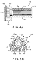
- Figs. 4A and 4B are a longitudinal sectional view and a cross-sectional view, respectively, of the locking clip 10.
- the cover 17 is removed.
- the selector lug 13a of the selector lever 13 is operated to turn the selector lever 13 from a neutral position indicated by solid lines in the direction of the arrow B (clockwise direction) to a first position indicated by two-dot chain lines
- the operating part 13d of the selector lever 13 turns the second pawl 14 (left pawl) counterclockwise against the resilience of the compression coil spring 15 to disengage the second pawl from the ratchet wheel 12b. Consequently, the roller assembly 12 is allowed to rotate counterclockwise.
- the first pawl 14 (right pawl) is kept engaged with the ratchet wheel 12b by the compression coil spring 15 because the operating part 13d of the selector lever 13 does not act on the first pawl 14.
- the roller assembly 12 is restrained from clockwise rotation, as viewed in Fig. 4B, by the first pawl 14 (right pawl) engaged with the ratchet wheel 12b and is allowed to rotate counterclockwise.
- the first pawl 14 (right pawl) is turned clockwise on its pivots and is disengaged from the ratchet wheel 12b against the resilience of the compression coil spring 15 by the teeth of the ratchet wheel 12b.
- the retaining spring 18 is in elastic contact with the operating part 13d of the selector lever 13.
- the selector lug 13a When the selector lug 13a is operated to turn the selector lever 13 to the first position, the retaining spring 18 comes into light contact with a first end, i.e., a right end as viewed in Fig. 4B, of the operating part 13d to retain the selector lever 13 at the first position. Consequently, the second compression coil spring 15 (left compression coil spring) is unable to turn the selector lever 13 counterclockwise and the selector lever 13 is retained at the first position even if the selector lug 13a is released free.
- the roller assembly 12 is restrained from counterclockwise rotation, as viewed in Fig. 4B, by the second pawl 14 (left pawl) engaged with the ratchet wheel 12b and is allowed to rotate clockwise.
- the second pawl 14 (left pawl) is turned counterclockwise on its pivots and is disengaged from the ratchet wheel 12b against the resilience of the second compression coil spring 15 by the teeth of the ratchet wheel 12b.
- the selector lever 13 is turned to the first or the second position to enable the roller assembly 12 to rotate counterclockwise or clockwise.
- the retaining spring 18 kept in elastic contact with the operating part 13d of the selector lever 13 comes into light contact with a second end, i.e., a left end as viewed in Fig. 4B, of the operating part 13d of the selector lever 13 when the selector lug 13a is operated to turn the selector lever 13 to the second position to retain the selector lever 13 at the second position. Consequently, the first compression coil spring 15 (right compression coil spring) is unable to turn the selector lever 13 clockwise and the selector lever 13 is retained at the second position even if the selector lug 13a is released free.
- Fig. 3 shows the locking clip 10 used in combination with the seat belt 1 for the right seat of the vehicle.
- the locking clip 10 is put on the seat belt 1 in a direction opposite the direction in which the locking clip 10 is put on the seat belt 1 in Fig. 3, the selector lever 13 of the ratchet mechanism is turned in the opposite direction to set the selector lever 13.
- the portions of the waist belt section 1a and the shoulder belt section 1b of the seat belt 1 in the vicinity of the belt slot are clamped together by the locking clip 10.
- the waist belt section 1a holding down the child car seat can be further tightened simply by pulling the shoulder belt section 1b and the waist belt section 1a is prevented from loosening by the locking clip 10.
- Figs. 5 to 7 show a locking clip 20 in a second embodiment of the present invention.
- the locking clip 20 can be divided into two parts, i.e., a base 30 and a belt pressing unit 40 mounted on the base 30.
- the base 30 is a member having a U-shaped cross section formed by bending a comparatively thick, substantially rectangular plate.
- the base 30 has a bottom wall 34 and side walls 32.
- Each side wall 32 is provided with an L-shaped slot 35 opening in the upper edge of the side wall 32, and a keyhole-shaped slot 36 opening in the rear end edge (right end edge as viewed in Fig. 5) of the side wall 32.
- the slot 36 has a narrow, straight section and a round end section.
- the bottom wall 34 is provided in a front portion thereof (left end portion as viewed in Fig. 5) with a T-shaped belt slot 37 opening in the front edge thereof.
- the bottom wall 34 may be provided with a belt groove similar to the belt slot 37 in a rear portion thereof. It is effective in keeping a seat belt 1 tight particularly when collision occurs to the bottom wall 34 provided with belt slots 37 in the opposite end portions thereof.
- Opposite flat end portions 63 of a support shaft 62 supporting a guide roller 64 are inserted in the narrow straight sections of the slots 36 with their flat surfaces extended in parallel to the narrow straight sections, and the support shaft 62 is turned after the flat end portions 63 have reached the round end sections so that the flat end portions 63 are retained in the round sections of the slots 36.
- the belt pressing unit 40 of the locking clip 20 has a support member 41 (pressing member) formed by processing a steel plate, a toothed cam shaft 50 extended between the opposite side walls of the support member 41, a guide roller 64 extended between the opposite side walls of the support member 41, and a locking pin 70 projecting from the support member 41.
- the base 30 and the support member 41 of the belt pressing unit 40 constitute a belt clamping mechanism.
- the toothed cam shaft 50, the locking pin 70 and the guide roller 64 constitute a ratchet mechanism.
- the support member 41 has, in an integral structure, a U-shaped part 42 (Fig. 7B) opening downward and having side portions 43, side parts 44 extending from the side portions 43 of the U-shaped part 42, and an upright part 46 extending upward from one of the side parts 44 and having a U-shaped portion 47 (Figs. 6 and 7B) formed by bending an upper end portion thereof.
- the toothed cam shaft 50 and the guide roller 64 are extended between and supported on the side parts 44 of the support member 41.
- the toothed cam shaft 50 is supported for rotation on the support shaft 52.
- the toothed cam shaft 50 is provided with teeth 58 in a region of its lower surface extending from a lowermost portion of the lower surface in a direction in which the seat belt 1 is pulled for tightening.
- the toothed cam shaft 50 has an arm 56 projecting upward from a portion thereof. In a state where the belt pressing unit 40 is combined with the base 30, a gap of a thickness twice the thickness of the seat belt 1 is formed between the teeth 58 of the toothed cam shaft 50 and the bottom wall 34 of the base 30.
- the toothed cam shaft 50 is urged to turn clockwise, i.e., in a direction opposite the direction of the arrow A, because the teeth 58 are in light contact with the shoulder belt section 1b. Consequently, the teeth 58 bite into the shoulder belt section 1b and hence the shoulder belt section 1b cannot be pulled. Thus the function of a ratchet mechanism is exercised.
- the locking pin 70 When it is desired to enable the shoulder belt section 1b to be pulled in either direction by nullifying the function of the ratchet mechanism, the locking pin 70 is operated.
- the locking pin 70 is supported at two points thereon on the U-shaped portion 47 of the upright part 46 extending upward from one of the side parts 44 of the belt pressing unit 40 so as to be advanced into and retracted from a turning region of the arm 56 of the toothed cam shaft 50.
- a stop ring 73 (Fig. 7B) is attached to the locking pin 70 and a compression coil spring 72 is compressed between an end section of the U-shaped portion 47 and the stop ring 73 to bias the locking pin 70 toward the turning region of the arm 56.
- the function of the ratchet mechanism can be nullified by the following procedure.
- the toothed cam shaft 50 is always biased clockwise, as viewed in Fig. 7A, by a return spring 54 locate the teeth 58 near the base 30.
- the free guide roller 64 disposed in parallel to the toothed cam shaft 50 at a predetermined distance in a direction in which the shoulder belt section 1b is pulled from the toothed cam shaft 50.
- the shoulder belt section 1b is wound around the guide roller 64 so that the same can be smoothly pulled in the direction of the arrow F without touching any part of the locking clip 20 for tightening. Since the guide roller 64 guides the seat belt 1 for movement along the bottom wall 34, useless contact between the seat belt 1 and the teeth 58 and the abrasion of the seat belt 1 can be avoided.
- the guide roller 64 is supported for rotation on the support shaft 62 having the opposite flat end portions and is biased in a predetermined direction by a return spring 66.
- a turning lever 60 is connected to the support shaft 62 to turn the support shaft 62.
- a locking clip in a modification of the second embodiment is provided with a toothed cam shaft 50 having a thick arm 56 provided with two grooves of different depths as shown in Figs. 8A and 8B.
- Fig. 8A(i) (ii) shows the positional relation between the arm 56 and the locking pin 70.
- Fig. 8A(ii) is a sectional view taken on line A-A in Fig. 8A(i).
- Fig. 8B(i)(ii) is a sectional view showing two possible positions of the locking pin 70 in the toothed cam shaft 50.
- the arm 56 is provided in the inner surface of a thick portion thereof with a deep, narrow groove 81 and a shallow, wide groove 82.
- the locking pin 70 supported on the U-shaped portion 47 of the upright part 46 can be placed at a first position shown in Fig. 8B(i) and a second position shown in Fig. 8B(ii).
- the arm 56 is able to turn counterclockwise in a wide angular range L1.
- the seat belt 1 can be maintained in a tight state with reliability by turning the arm 56 counterclockwise, as viewed in Fig. 8A(i), and pushing the locking pin 70 into the deep, narrow groove 81 as shown in Fig. 8B(ii) after pulling the shoulder belt section 1b toward the retractor.
- the semicylindrical parts 11a covering the clamping roller 12a and serving as a shoulder belt section holding plate of the locking clip 10 in the first embodiment are immovable relative to the clamping roller 12a.
- the casing 11 may be provided with hinged holding plates capable of being turned on hinges relative to the clamping roller 12a instead of the fixed semicylindrical parts 11a. When the hinged holding plates are turned away from the clamping roller 12a to expose the clamping roller 12a, the locking clip 10 can be easily attached to the seat belt by a simple operation.
- the base 30 and the support member 41 of the belt pressing unit 40 of the locking clip 20 in the second embodiment are separate members.
- the connection of the base 30 and the support member 41 by a hinge will facilitate handling the locking clip 20 and will prevent loosing the base 30 and the support member 41.
- the locking clip 20 can be easily attached to the seat belt when the same is opened by turning the base 30 and the belt pressing unit 40 on the hinge.
Abstract
Description
- The present invention relates to a locking clip and, more specifically, to a locking clip connected to a seat belt fastening a child car seat to a seat of a vehicle to lock the seat belt.
- Fig. 9 is a perspective view of a
child car seat 4 placed on aseat 2 of a vehicle. Generally, thechild car seat 4 is fastened to theseat 2 of the vehicle by aseat belt 1 of the vehicle as shown in Fig. 9. In Fig. 9, theseat belt 1 includes awaist belt section 1a and ashoulder belt section 1b. One end of thewaist belt section 1a is secured to a position under aseat cushion 3 of theseat 2, and one end of theshoulder belt section 1b is secured to a position above a seat back of theseat 2 through a retractor, not shown. Atongue 1c is connected to the other ends of thewaist belt section 1a and theshoulder belt section 1b. Referring to Fig. 9, thechild car seat 4 is placed on theseat 2, thetongue 1c connected to theseat belt 1 is passed through abelt slot 6 formed in one side wall of abase 5 included in thechild car seat 4 and another belt slot formed in the other side wall of thebase 5 and is engaged with a buckle 7 (Figs. 10A and 10B) disposed beside theseat cushion 3 of theseat 2. Thechild car seat 4 may be set on theseat 2 so that a child car seated on the child car seat faces either forward or rearward. - Figs. 10A and 10B are partly sectional front elevations of the
seat 2 of the vehicle and thechild car seat 4 mounted on theseat 2 and fastened to theseat 2 with theseat belt 1. In Fig. 10A, theseat belt 1 is passed across thebase 5 of thechild car seat 2 and simply holding thechild car seat 2 in place. In Fig. 10B, theseat belt 1 passed across thebase 5 of thechild car seat 2 is tightened by a locking clip. Although thetongue 1c is engaged with thebuckle 7, aportion 1b' of theshoulder belt section 1b of theseat belt 1 extending near thebelt slot 6 is separated from thewaist belt section 1a of theseat belt 1 and hence thechild car seat 4 cannot be securely held on theseat 2. - As shown in Fig. 10B, respective portions of the
waist belt section 1a and theshoulder belt section 1b of theseat belt 1 fastening thechild car seat 4 to theseat 2 extending near thebelt slot 6 are superposed and are bound together with alocking clip 9 to fasten thechild car seat 4 firmly to theseat 2 by theseat belt 1. - The
locking clip 9 is, for example, a comblike plate provided with bars. The superposed portions of thewaist belt section 1a and theshoulder belt section 1b are passed alternately above and below the alternate bars to hold frictionally together the superposed portions of thewaist belt section 1a and theshoulder belt section 1b. - If the
child car seat 4 is still loosely fastened to theseat 2 even if the superposed portions of thewaist belt section 1a and theshoulder belt section 1b are bound together with thecomblike locking clip 9, theshoulder belt section 1b must be further pulled toward the retractor for tightening. When pulling theshoulder belt section 1b toward the retractor for tightening, a portion of theseat belt 1 extending between the bars of thecomblike locking clip 9 must be released from thecomblike locking clip 9, a slack in theseat belt 1 must be pulled into the retractor and thelocking clip 9 must be put on theseat belt 1 again, which requires troublesome work. - Accordingly, it is an object of the present invention to provide a locking clip that simplifies an operation to increase the tightness of a seat belt fastening a child car seat to a seat of a vehicle to hold the child car seat securely on the seat of the vehicle.
- According to the present invention, there is provided a locking clip to be attached to a portion of a seat belt having a waist belt section securely fastening a child car seat to a seat of a vehicle and a shoulder belt section, at which the waist belt section and the shoulder belt section diverge from each other. The locking clip includes: a belt clamping mechanism for clamping together the waist belt section and the shoulder belt section; and a ratchet mechanism for permitting the shoulder belt section clamped by the belt clamping mechanism to be pulled only in one direction.
- Thus, the seat belt fastening the child car seat to the seat of the vehicle can be further tightened simply by pulling the shoulder belt section of the seat belt toward a belt retractor to fasten the child car seat more firmly and securely to the seat of the vehicle.
- Preferably, the belt clamping mechanism includes a casing, and a rotating member disposed in the casing so as to clamp the waist belt section and the shoulder belt section between the casing and the rotating member. Also, it is preferred that the ratchet mechanism includes a ratchet wheel fixedly connected to the rotating member, and a holding link biased toward the ratchet wheel so as to be engaged with the ratchet wheel to permit the ratchet wheel to rotate only in one direction.
- Thus, the ratchet mechanism is simple in construction, is easy to operate and operates with reliability.
- Preferably, the rotating member has a circumference of an antislip shape capable of ensuring a firm grip. It is preferred that the antislip shape has a plurality of circumferentially arranged, elongate, axial ridges. Also, it is preferred that the antislip shape has a plurality of fine knobs.
- Thus, the antislip shape of the circumference of the rotating member ensures a firm grip of the seat belt by the rotating member and ensures the effect of the ratchet mechanism.
- Preferably, the ratchet mechanism includes a ratchet wheel fixedly connected to the rotating member, a pair of holding links biased toward the ratchet wheel so as to be engaged with the ratchet wheel to permit the ratchet wheel to rotate only in one direction, with one of the hold links to permit the ratchet wheel to rotate in a direction and the other hold link to permit the ratchet wheel to rotate in a direction opposite the former, and a selector lever capable of being turned from a neutral position to a first position to disengage one of the holding links from the ratchet wheel and of being turned from the neutral position to a second position to disengage the other holding link from the ratchet wheel.
- Since the rotating direction of the ratchet wheel can be selectively determined, the child car seat can be fastened to either the right or the left seat of the vehicle.
- According to the present invention, the ratchet mechanism may include a base, and a pressing member extended parallel to the base so as to clamp the waist belt section and the shoulder belt section between the base and the pressing member.
- Preferably, the ratchet mechanism includes a toothed cam shaft supported for turning on the pressing member and biased toward the base so as to engage teeth of the toothed cam shaft with the shoulder belt section clamped between the base and the pressing member to permit the shoulder belt section to move only in one direction.
- Preferably, the ratchet mechanism further includes a locking member for restraining the toothed cam shaft from turning. It is preferred that the toothed cam shaft is provided with two grooves differing from each other in width, the toothed cam shaft is able to turn when the locking member is inserted in one of the grooves, and the toothed cam shaft is unable to turn when the locking member is inserted in the other groove.
- Thus, the seat belt can be surely locked after being pulled for tightening.
- Preferably, the ratchet mechanism is provided with a guide roller spaced a predetermined distance in the direction of travel of the seat belt from the toothed cam shaft to guide at least the shoulder belt section in its moving direction.
- Since the shoulder belt section can be pulled in parallel to the base, the toothed cam shaft can be positively engaged with and disengaged from the shoulder belt section, and the tightness of the seat belt can be easily increased.
- The above and other objects, features and advantages of the present invention will become more apparent from the following description taken in connection with the accompanying drawings, in which:
- Fig. 1 is an exploded perspective view of a locking clip in a first embodiment of the present invention;
- Fig. 2 is a perspective view of the locking clip of Fig. 1 as assembled and viewed from the opposite side of Fig. 1;
- Fig. 3 is a perspective view of the locking clip of Fig. 1 in use;
- Figs. 4A and 4B are an enlarged longitudinal sectional view and an enlarged cross-sectional view, respectively, of the locking clip of Fig. 1;
- Fig. 5 is an exploded perspective view of a locking clip in a second embodiment of the present invention;
- Fig. 6 is a perspective view of the locking clip of Fig. 5 as assembled;
- Figs. 7A and 7B are an enlarged cross-sectional view and an enlarged end view, respectively, of the locking clip of Fig. 5;
- Fig. 8A is a schematic view showing the positional relation between a toothed cam shaft and a locking pin;
- Fig. 8B is a schematic sectional view of assistance in explaining two positions of the locking pin relative to the toothed cam shaft;
- Fig. 9 is a perspective view of a child car seat as mounted on a seat of a vehicle;
- Fig. 10A is partly sectional front elevation of the seat of the vehicle and the child car seat mounted on and fastened with a seat belt to the seat; and
- Fig. 10B is a partly sectional front elevation of the seat of the vehicle and the child car seat mounted on and fastened with a seat belt to the seat, in which the seat belt is tightened by a locking clip.
-
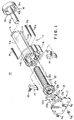
- Referring to Fig. 1 showing a
locking clip 10 in a first embodiment of the present invention, the lockingclip 10 has a casing 11, acap 16 attached to one end of the casing 11, acover 17 fastened to the other end of the casing 11 with bolts B1 to B3 and nuts N1 to N3. Aroller assembly 12 formed by uniting together a clampingroller 12a (rotating member) and aratchet wheel 12b, aselector lever 13, first and second pawls 14 (holding links), first and second compression coil springs 15 and a retaining spring 18 (Fig. 4B) are contained in the casing 11. - The casing 11 and the clamping
roller 12a constitute a belt clamping mechanism. Theratchet wheel 12b, theselector lever 13, thepawls 14 and the compression springs 15 constitute a ratchet mechanism. - The casing 11 has upper and lower semicylindrical parts 11a having a substantially semicylindrical shape and extending opposite to each other with a space of a width t1 (Fig. 3) twice the thickness of a
seat belt 1 therebetween, and abase part 11b defining a space for containing parts. The semicylindrical parts 11a extend from thebase part 11b in a cantilever fashion.Flanges 11c are formed on the free ends of the semicylindrical parts 11a, respectively. Theflanges 11c are inserted throughrecesses 16c formed in thecap 16 into thecap 16. The clampingroller 12a of theroller assembly 12 is extended in a cylindrical space defined by the two semicylindrical parts 11a. When the clampingroller 12a is inserted in the cylindrical space defined by the semicylindrical parts 11a, a substantially annular space of a thickness approximately equal to the thickness of theseat belt 1 is formed between each semicylindrical part 11a and the clampingroller 12a. - The space defined by the
base part 11b of the casing 11 has a cylindrical section in which theratchet wheel 12b of theroller assembly 12 is placed, and two parallelepipedic sections having the shape substantially resembling a rectangular solid in which the first and thesecond pawls 14 and the first and the secondcompression coil spring 15 are placed. The parallelepipedic sections open into the cylindrical section. - Combinations of the
pawls 14 and the compression coil springs 15 are placed in the two parallelepipedic sections, respectively. Thepawls 14 are biased toward the cylindrical space by the compression coil springs 15. Eachpawl 14 has pivots respectively projecting from the opposite sides of a lower end portion thereof. One of the pivots is fitted in a hole, not shown, formed in the inner surface of thecover 17 and the other pivot is fitted in a hole, not shown, formed in thebase part 11b to support thepawl 14 for turning on the pivots so that an upper end portion of thepawl 14 can be advanced into and retracted from the cylindrical space of thecasing 11b. - The
roller assembly 12 is formed by uniting together the clampingroller 12a having a knurled circumference capable of exerting frictional resistance against the movement of theseat belt 1, and theratchet wheel 12b having teeth on its circumference. The knurled circumference may have any suitable shape capable of exerting high frictional resistance against the movement of theseat belt 1, such as a shape having longitudinal ridges formed by knurling or a shape having fine knobs formed by embossing. The clampingroller 12a is provided in one end portion thereof with an axialcylindrical bore 12d as shown in Fig. 2. Ashaft 16a coaxially projecting from the inner surface of thecap 16 is fitted in thecylindrical bore 12d of the clampingroller 12a. Theratchet wheel 12b has acylindrical center hole 12c. Anannular ridge 13b formed on one surface of theselector lever 13 is fitted in thecenter hole 12c of theratchet wheel 12b. - The clamping
roller 12a of theroller assembly 12 is inserted in the casing 11 through the cylindrical space of thebase part 11b so that the clampingroller 12a is extended in the cylindrical space defined by the semicylindrical parts 11a, and theratchet wheel 12b is set in the cylindrical space of thebase part 11b. - The
selector lever 13 has a body having the shape of a circular, thin plate, aselector lug 13a projecting radially outward from a portion of the body, anoperating part 13d projecting radially outward from a portion of the body diametrically opposite to the portion from which theselector lug 13a projects, and theannular ridge 13b. Theselector lever 13 is provided with acenter hole 13c. Theselector lever 13 is put on theratchet wheel 12b with theannular ridge 13b thereof fitted in the center bore 12c of theratchet wheel 12b so that theselector lug 13a extends upward. Thepawls 14 are placed in the parallelepipedic spaces, being biased toward the cylindrical space by the compression coil springs 15 so as to be engaged with the teeth of theratchet wheel 12b, respectively. Thecover 17 is fastened closely to thebase part 11b with the bolts B1 to B3 and the nuts N1 to N3. More specifically, the bolts B1, B2 and B3 are inserted in through holes formed in thebase part 11b of the casing 11 and through holes formed in thecover 17, and the nuts N1, N2 and N3 are screwed on the bolts B1, B2 and B3 to fasten thecover 17 to the casing 11. - When the
cover 17 is thus closely fastened to thebase part 11b, a gap is formed between thecover 17 and thebase part 11b to enable theselector lug 13a to project from thebase part 11b and to be turned. - Fig. 2 is a perspective view of the locking
clip 10 as viewed from the side of thecap 16 in Fig. 1. As shown in Fig. 2, the clampingroller 12a is extended in the cylindrical space defined by the semicylindrical parts 11a of the casing 11 and substantially annular space of a thickness corresponding to the thickness of theseat belt 1 are formed between the clampingroller 12a and the semicylindrical parts 11a. - As shown in Fig. 3, a shoulder belt section (an upper belt section) and a waist belt section (lower belt section) of the
seat belt 1 are inserted in upper and lower portions of the annular space formed in thelocking clip 10, respectively, and thecap 16 is put on the free ends of the semicylindrical parts 11a of the housing 11 to keep the shoulder belt section and the waist belt section in thelocking clip 10. - The
shaft 16a of thecap 16 is fitted in thecylindrical bore 12d of the clampingroller 12a, thecap 16 is pressed against the free ends of the semicylindrical parts 11a of the casing 11 and thecap 16 is turned to receive theflanges 11c of the casing 11 through therecesses 16c (Fig. 1) of thecap 16 in thecap 16. Then, thecap 16 is turned through a small angle. Consequently, theflanges 11c of the casing 11 are moved into spaces between the end wall of thecap 16 and inner flanges 16b formed on the open end of thecap 16. Thus, thecap 16 is fastened to the casing 11. The lockingclip 10 is thus assembled. - Figs. 4A and 4B are a longitudinal sectional view and a cross-sectional view, respectively, of the locking
clip 10. In Fig. 4B, thecover 17 is removed. Referring to Fig. 4B, when theselector lug 13a of theselector lever 13 is operated to turn theselector lever 13 from a neutral position indicated by solid lines in the direction of the arrow B (clockwise direction) to a first position indicated by two-dot chain lines, the operatingpart 13d of theselector lever 13 turns the second pawl 14 (left pawl) counterclockwise against the resilience of thecompression coil spring 15 to disengage the second pawl from theratchet wheel 12b. Consequently, theroller assembly 12 is allowed to rotate counterclockwise. In this state, the first pawl 14 (right pawl) is kept engaged with theratchet wheel 12b by thecompression coil spring 15 because theoperating part 13d of theselector lever 13 does not act on thefirst pawl 14. - Thus, the
roller assembly 12 is restrained from clockwise rotation, as viewed in Fig. 4B, by the first pawl 14 (right pawl) engaged with theratchet wheel 12b and is allowed to rotate counterclockwise. When theratchet wheel 12b is rotated counterclockwise, the first pawl 14 (right pawl) is turned clockwise on its pivots and is disengaged from theratchet wheel 12b against the resilience of thecompression coil spring 15 by the teeth of theratchet wheel 12b. - The retaining
spring 18 is in elastic contact with the operatingpart 13d of theselector lever 13. When theselector lug 13a is operated to turn theselector lever 13 to the first position, the retainingspring 18 comes into light contact with a first end, i.e., a right end as viewed in Fig. 4B, of theoperating part 13d to retain theselector lever 13 at the first position. Consequently, the second compression coil spring 15 (left compression coil spring) is unable to turn theselector lever 13 counterclockwise and theselector lever 13 is retained at the first position even if theselector lug 13a is released free. - When the
selector lug 13a of theselector lever 13 is operated to turn theselector lever 13 counterclockwise from the neutral position to a second position, not shown, the operatingpart 13d of theselector lever 13 turns the first pawl 14 (right pawl) clockwise against the resilience of thecompression coil spring 15 to disengage thefirst pawl 14 from theratchet wheel 12b. Consequently, theroller assembly 12 is allowed to rotate clockwise. In this state, the second pawl 14 (left pawl) is kept engaged with theratchet wheel 12b by the secondcompression coil spring 15 because theoperating part 13d of theselector lever 13 does not act on thesecond pawl 14. Thus, theroller assembly 12 is restrained from counterclockwise rotation. - Thus, the
roller assembly 12 is restrained from counterclockwise rotation, as viewed in Fig. 4B, by the second pawl 14 (left pawl) engaged with theratchet wheel 12b and is allowed to rotate clockwise. When theratchet wheel 12b is rotated clockwise, the second pawl 14 (left pawl) is turned counterclockwise on its pivots and is disengaged from theratchet wheel 12b against the resilience of the secondcompression coil spring 15 by the teeth of theratchet wheel 12b. - The
selector lever 13 is turned to the first or the second position to enable theroller assembly 12 to rotate counterclockwise or clockwise. - The retaining
spring 18 kept in elastic contact with the operatingpart 13d of theselector lever 13 comes into light contact with a second end, i.e., a left end as viewed in Fig. 4B, of theoperating part 13d of theselector lever 13 when theselector lug 13a is operated to turn theselector lever 13 to the second position to retain theselector lever 13 at the second position. Consequently, the first compression coil spring 15 (right compression coil spring) is unable to turn theselector lever 13 clockwise and theselector lever 13 is retained at the second position even if theselector lug 13a is released free. - A method of using the
locking clip 10 provided with the ratchet mechanism will be described with reference to Figs. 1 to 3. - 1) A child car seat is placed on a seat of a vehicle so
as to face the front or the rear, a tongue connected to the
seat belt 1 is passed from one side of the child car seat through a belt slot formed in one of the side walls of the base of the child car seat and is pulled out through a belt slot formed in the other side wall of the base on the other side of the child car seat, the tongue is engaged with a buckle disposed beside the seat of the vehicle to fasten the child car seat tentatively to the seat of the vehicle (Fig. 10A). - 2) Then, the
cap 16 is turned to an angular position where therecesses 16c formed in the inner flange formed at the open end of thecap 16 coincide with theflanges 11c of the semicylindrical parts 11a, and thecap 16 is separated from the semicylindrical parts 11a of the casing 11 as shown in Fig. 1. - 3) Respective portions of the
waist belt section 1a and theshoulder belt section 1b in the vicinity of the belt slot are pulled together. Then, thewaist belt section 1a is inserted in the space between the clampingroller 12a and the upper semicylindrical part 11a, and theshoulder belt section 1b is inserted in the space between the clampingroller 12a and the lower semicylindrical part 11a as shown in Fig. 3. - 4) The operations carried out to separate the
cap 16 from the semicylindrical parts 11a are reversed to join thecap 16 to the semicylindrical parts 11a to complete work for attaching the lockingclip 10 to theseat belt 1. - 5) If the child car seat is not firmly fastened to the
seat of the vehicle after the
locking clip 10 has been thus attached to theseat belt 1, theselector lever 13 of the ratchet mechanism is turned to the first position or the second position, and theshoulder belt section 1b of theseat belt 1 is pulled in the direction of the blank arrows (Fig. 3). Consequently, the seat belt is further tightened and thewaist belt section 1a holding down the child car seat cannot be loosened even if thewaist belt section 1a is pulled in a direction opposite the direction of the blank arrow because the clampingroller 12a of the lockingclip 10 is able to rotate in only a single direction. -
- Fig. 3 shows the locking
clip 10 used in combination with theseat belt 1 for the right seat of the vehicle. When the lockingclip 10 is used in combination with theseat belt 1 for the left seat of the vehicle, the lockingclip 10 is put on theseat belt 1 in a direction opposite the direction in which thelocking clip 10 is put on theseat belt 1 in Fig. 3, theselector lever 13 of the ratchet mechanism is turned in the opposite direction to set theselector lever 13. - Thus, the portions of the
waist belt section 1a and theshoulder belt section 1b of theseat belt 1 in the vicinity of the belt slot are clamped together by the lockingclip 10. Thewaist belt section 1a holding down the child car seat can be further tightened simply by pulling theshoulder belt section 1b and thewaist belt section 1a is prevented from loosening by the lockingclip 10. - Figs. 5 to 7 show a
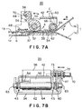
locking clip 20 in a second embodiment of the present invention. Referring to Fig. 5, the lockingclip 20 can be divided into two parts, i.e., abase 30 and abelt pressing unit 40 mounted on thebase 30. - The
base 30 is a member having a U-shaped cross section formed by bending a comparatively thick, substantially rectangular plate. Thebase 30 has abottom wall 34 andside walls 32. Eachside wall 32 is provided with an L-shapedslot 35 opening in the upper edge of theside wall 32, and a keyhole-shapedslot 36 opening in the rear end edge (right end edge as viewed in Fig. 5) of theside wall 32. Theslot 36 has a narrow, straight section and a round end section. Thebottom wall 34 is provided in a front portion thereof (left end portion as viewed in Fig. 5) with a T-shapedbelt slot 37 opening in the front edge thereof. Thebottom wall 34 may be provided with a belt groove similar to thebelt slot 37 in a rear portion thereof. It is effective in keeping aseat belt 1 tight particularly when collision occurs to thebottom wall 34 provided withbelt slots 37 in the opposite end portions thereof. - Opposite end portions of a
support shaft 52 of thebelt pressing unit 40 engage in the L-shapedslots 35, respectively. Oppositeflat end portions 63 of asupport shaft 62 supporting aguide roller 64 are inserted in the narrow straight sections of theslots 36 with their flat surfaces extended in parallel to the narrow straight sections, and thesupport shaft 62 is turned after theflat end portions 63 have reached the round end sections so that theflat end portions 63 are retained in the round sections of theslots 36. - As shown in Fig. 5, the
belt pressing unit 40 of the lockingclip 20 has a support member 41 (pressing member) formed by processing a steel plate, atoothed cam shaft 50 extended between the opposite side walls of thesupport member 41, aguide roller 64 extended between the opposite side walls of thesupport member 41, and alocking pin 70 projecting from thesupport member 41. - The
base 30 and thesupport member 41 of thebelt pressing unit 40 constitute a belt clamping mechanism. Thetoothed cam shaft 50, the lockingpin 70 and theguide roller 64 constitute a ratchet mechanism. - The
support member 41 has, in an integral structure, a U-shaped part 42 (Fig. 7B) opening downward and havingside portions 43,side parts 44 extending from theside portions 43 of theU-shaped part 42, and anupright part 46 extending upward from one of theside parts 44 and having a U-shaped portion 47 (Figs. 6 and 7B) formed by bending an upper end portion thereof. - The
toothed cam shaft 50 and theguide roller 64 are extended between and supported on theside parts 44 of thesupport member 41. Thetoothed cam shaft 50 is supported for rotation on thesupport shaft 52. As shown in Fig. 7A, thetoothed cam shaft 50 is provided withteeth 58 in a region of its lower surface extending from a lowermost portion of the lower surface in a direction in which theseat belt 1 is pulled for tightening. Thetoothed cam shaft 50 has anarm 56 projecting upward from a portion thereof. In a state where thebelt pressing unit 40 is combined with thebase 30, a gap of a thickness twice the thickness of theseat belt 1 is formed between theteeth 58 of thetoothed cam shaft 50 and thebottom wall 34 of thebase 30. When awaist belt section 1a and ashoulder belt section 1b of theseat belt 1 are superposed in the gap between theteeth 58 and thebottom wall 34, some of theteeth 58 are in light contact with theshoulder belt section 1b in a light contact state. When theshoulder belt section 1b is pulled in the direction of the arrow F toward a retractor in the light contact state, thetoothed cam shaft 50 is urged to turn counterclockwise indicated by the arrow A in Fig. 7A because theteeth 58 are in light contact with theshoulder belt section 1b. Consequently, theteeth 58 are moved away from theshoulder belt section 1b and do not bite into theshoulder belt section 1b, so that theshoulder belt section 1b can be pulled in the direction of the arrow F. If theshoulder belt section 1b is pulled in the direction of the arrow G in Fig. 7A, thetoothed cam shaft 50 is urged to turn clockwise, i.e., in a direction opposite the direction of the arrow A, because theteeth 58 are in light contact with theshoulder belt section 1b. Consequently, theteeth 58 bite into theshoulder belt section 1b and hence theshoulder belt section 1b cannot be pulled. Thus the function of a ratchet mechanism is exercised. - When it is desired to enable the
shoulder belt section 1b to be pulled in either direction by nullifying the function of the ratchet mechanism, the lockingpin 70 is operated. The lockingpin 70 is supported at two points thereon on theU-shaped portion 47 of theupright part 46 extending upward from one of theside parts 44 of thebelt pressing unit 40 so as to be advanced into and retracted from a turning region of thearm 56 of thetoothed cam shaft 50. A stop ring 73 (Fig. 7B) is attached to the lockingpin 70 and acompression coil spring 72 is compressed between an end section of theU-shaped portion 47 and thestop ring 73 to bias the lockingpin 70 toward the turning region of thearm 56. - The function of the ratchet mechanism can be nullified by the following procedure.
- (1) The
locking pin 70 is pulled against the resilience of thecompression coil spring 72 to retract the lockingpin 70 from the turning region of thearm 56. - (2) The
arm 56 is turned counterclockwise, as viewed in Fig. 7A. - (3) The
locking pin 70 is released after turning thearm 56 in a counterclockwise direction beyond a position corresponding to the lockingpin 70. - (4) The
locking pin 70 advances into the turning region of thearm 56. - (5) The clockwise turning of the
arm 56 is prevented by the lockingpin 70 and hence thearm 56 is unable to return to its original position even if the same is released. In this state, theteeth 58 of thetoothed cam shaft 50 are moved upward away from thebottom wall 34 and hence theteeth 58 are unable to bite into theshoulder belt section 1b when theshoulder belt section 1b is pulled in either direction. Thus, the function of the ratchet mechanism is nullified. -
- The
toothed cam shaft 50 is always biased clockwise, as viewed in Fig. 7A, by areturn spring 54 locate theteeth 58 near thebase 30. - The
free guide roller 64 disposed in parallel to thetoothed cam shaft 50 at a predetermined distance in a direction in which theshoulder belt section 1b is pulled from thetoothed cam shaft 50. Theshoulder belt section 1b is wound around theguide roller 64 so that the same can be smoothly pulled in the direction of the arrow F without touching any part of the lockingclip 20 for tightening. Since theguide roller 64 guides theseat belt 1 for movement along thebottom wall 34, useless contact between theseat belt 1 and theteeth 58 and the abrasion of theseat belt 1 can be avoided. - The
guide roller 64 is supported for rotation on thesupport shaft 62 having the opposite flat end portions and is biased in a predetermined direction by areturn spring 66. A turninglever 60 is connected to thesupport shaft 62 to turn thesupport shaft 62. - A method of using the
locking clip 20 provided with the ratchet mechanism will be described. - 1) A child car seat is placed on a seat of a vehicle so
as to face the front or the rear, a tongue connected to the
seat belt 1 is passed from one side of the child car seat through a belt slot formed in one of the side walls of the base of the child car seat and is pulled out through a belt slot formed in the other side wall of the base on the other side of the child car seat, the tongue is engaged with a buckle disposed beside the seat of the vehicle to fasten the child car seat tentatively to the seat of the vehicle (Fig. 10A). - 2) Then, the turning
lever 60 is turned against the resilience of thereturn spring 66 to set the flats of the opposite end portions of thesupport shaft 62 horizontally, the opposite end portions of thesupport shaft 62 are pulled out of the keyhole-shapedslots 36 and opposite end portions of thesupport shaft 52 supporting thetoothed cam shaft 50 are pulled out of the L-shapedslots 35 of the base 30 to separate thebelt pressing unit 40 from the base 30 as shown in Fig. 5. - 3) The
waist belt section 1a is passed through the T-shapedbelt slot 37 of thebottom wall 34 of thebase 30, theshoulder belt section 1b is extended on thebottom wall 34, and thebase 30 and thebelt pressing unit 40 are assembled. The operations for separating the base 30 from thebelt pressing unit 40 are reversed to assemble thebase 30 and thebelt pressing unit 40; that is, thelever 60 is turned in the direction of the arrow C, as viewed in Fig. 5, to set the flats of theopposite end portions 63 of thesupport shaft 62 horizontally, theopposite end portions 63 of thesupport shaft 62 are inserted in the keyhole-shapedslots 36 formed in theside walls 32, thelever 60 is turned in a direction opposite the direction of the arrow C after theflat end portions 63 have reached the round end sections of the keyhole-shapedslots 36 so that theflat end portions 63 are retained in the round sections of theslots 36 and, at the same time, the opposite end portions of thesupport shaft 52 supporting thetoothed cam shaft 50 are inserted in the L-shapedslots 35 of thebase 30. Thus, thetoothed cam shaft 50 and theguide roller 64 of thebelt pressing unit 40 are disposed with a gap of the predetermined thickness formed between thebottom wall 34 of thebase 30, and thetoothed cam shaft 50 and theguide roller 64. - 4) Figs. 7A and 7B show the assembly of the
base 30 and thebelt pressing unit 40. Theseat belt 1 can be tightened by pulling theshoulder belt section 1b toward the retractor. -
- To ensure that the
seat belt 1 is maintained in the tight state, a locking clip in a modification of the second embodiment is provided with atoothed cam shaft 50 having athick arm 56 provided with two grooves of different depths as shown in Figs. 8A and 8B. Fig. 8A(i) (ii) shows the positional relation between thearm 56 and the lockingpin 70. Fig. 8A(ii) is a sectional view taken on line A-A in Fig. 8A(i). Fig. 8B(i)(ii) is a sectional view showing two possible positions of the lockingpin 70 in thetoothed cam shaft 50. - As shown in Fig. 8A(ii), the
arm 56 is provided in the inner surface of a thick portion thereof with a deep,narrow groove 81 and a shallow,wide groove 82. As shown in Figs. 8B(i)(ii), the lockingpin 70 supported on theU-shaped portion 47 of theupright part 46 can be placed at a first position shown in Fig. 8B(i) and a second position shown in Fig. 8B(ii). When the lockingpin 70 is at the first position shown in Fig. 8B(i), thearm 56 is able to turn counterclockwise in a wide angular range L1. Since thearm 56 is able to turn counterclockwise until aninner surface 84 of the shallow,wide groove 82 comes into contact with the lockingpin 70 when theshoulder belt section 1b is pulled toward the retractor, theteeth 58 of thetoothed cam shaft 50 are moved away from thebottom wall 34 as shown in Fig. 7A and do not bite into theshoulder belt section 1b, so that theseat belt 1 can be tightened. - When the locking
pin 70 is at the second position in the deep,narrow groove 81 as shown in Fig. 8B (ii), thetoothed cam shaft 50 is turned so that theteeth 58 shown in Fig. 7A are located nearest to thebottom wall 34 and theteeth 58 are deeply engaged with theshoulder belt section 1b. Since thearm 56 cannot be turned any further in a counterclockwise direction, theseat belt 1 cannot be further tightened. - Thus, the
seat belt 1 can be maintained in a tight state with reliability by turning thearm 56 counterclockwise, as viewed in Fig. 8A(i), and pushing the lockingpin 70 into the deep,narrow groove 81 as shown in Fig. 8B(ii) after pulling theshoulder belt section 1b toward the retractor. - Although the present invention has been described in terms of the two preferred embodiments thereof, the present invention is not limited thereto in its practical application and changes and improvements may be made therein.
- For example, the semicylindrical parts 11a covering the clamping
roller 12a and serving as a shoulder belt section holding plate of the lockingclip 10 in the first embodiment are immovable relative to the clampingroller 12a. The casing 11 may be provided with hinged holding plates capable of being turned on hinges relative to the clampingroller 12a instead of the fixed semicylindrical parts 11a. When the hinged holding plates are turned away from the clampingroller 12a to expose the clampingroller 12a, the lockingclip 10 can be easily attached to the seat belt by a simple operation. - The
base 30 and thesupport member 41 of thebelt pressing unit 40 of the lockingclip 20 in the second embodiment are separate members. The connection of thebase 30 and thesupport member 41 by a hinge will facilitate handling thelocking clip 20 and will prevent loosing thebase 30 and thesupport member 41. The lockingclip 20 can be easily attached to the seat belt when the same is opened by turning thebase 30 and thebelt pressing unit 40 on the hinge. - Although the invention has been described in its preferred embodiments with a certain degree of particularity, obviously many changes and variations are possible therein. It is therefore to be understood that the present invention may be practiced otherwise than as specifically described herein without departing from the scope and spirit thereof.
Claims (14)
- A locking clip to be attached to a portion of a seat belt having a waist belt section securely fastening a child car seat to a seat of a vehicle and a shoulder belt section, at which the waist belt section and the shoulder belt section diverge from each other, said locking clip comprising:a belt clamping mechanism for clamping the waist belt section and the shoulder belt section; anda ratchet mechanism for permitting the shoulder belt section clamped by the belt clamping mechanism to be pulled only in one direction.
- The locking clip according to claim 1, wherein the belt clamping mechanism includes a casing, and a rotating member disposed in the casing so as to clamp the waist belt section and the shoulder belt section between the casing and the rotating member.
- The locking clip according to claim 2, wherein the ratchet mechanism includes a ratchet wheel fixedly connected to the rotating member, and a holding link biased toward the ratchet wheel so as to be engaged with the ratchet wheel to permit the ratchet wheel to rotate only in one direction.
- The locking clip according to claim 2, wherein the casing has a cylindrical part extended so as to define an annular space of a predetermined thickness, between which the seat belt is clamped, between the circumference of the rotating member and the cylindrical part, and the cylindrical part is provided with slits of a width corresponding to a thickness of the seat belt.
- The locking clip according to claim 4, wherein the cylindrical part has a pair of substantially semicylindrical sections spaced a distance corresponding to the thickness of the seat belt apart from each other, the shoulder belt section is clamped between one of the substantially semicylindrical section and the rotating member, and the waist belt section is clamped between the other substantially semicylindrical section and the rotating member.
- The locking clip according to one of claims 2 to 5, wherein the rotating member has a circumference of an antislip shape capable of ensuring a firm grip.
- The locking clip according to claim 6, wherein the antislip shape has a plurality of circumferentially arranged, elongate, axial ridges.
- The locking clip according to claim 6, wherein the antislip shape has a plurality of fine knobs.
- The locking clip according to one of claims 2 to 8, wherein the ratchet mechanism includes a ratchet wheel fixedly connected to the rotating member, a pair of holding links biased toward the ratchet wheel so as to be engaged with the ratchet wheel to permit the ratchet wheel to rotate only in one direction, with one of the hold links to permit the ratchet wheel to rotate in a direction and the other hold link to permit the ratchet wheel to rotate in a direction opposite the former, a selector lever capable of being turned from a neutral position to a first position to disengage one of the holding links from the ratchet wheel and of being turned from the neutral position to a second position to disengage the other holding link from the ratchet wheel.
- The locking clip according to claim 1, wherein the belt clamping mechanism includes a base, and a pressing member extended parallel to the base so as to clamp the waist belt section and the shoulder belt section between the base and the pressing member.
- The locking clip according to claim 10, wherein the ratchet mechanism includes a toothed cam shaft supported for turning on the pressing member and biased toward the base so as to engage teeth of the toothed cam shaft with the shoulder belt section clamped between the base and the pressing member to permit the shoulder belt section to move only in one direction.
- The locking clip according to claim 11, wherein the ratchet mechanism further includes a locking member for restraining the toothed cam shaft from turning.
- The locking clip according to claim 12, wherein the toothed cam shaft is provided with two grooves differing from each other in width, the toothed cam shaft is turnable when the locking member is inserted in one of the grooves, and the toothed cam shaft is unable to turn when the locking member inserted in the other groove.
- The locking clip according to one of claims 11 to 13, wherein the ratchet mechanism further includes a guide roller spaced a predetermined distance in a direction in which the seat belt is moved from the toothed cam shaft to guide at least the shoulder belt section in its moving direction.
Applications Claiming Priority (2)
| Application Number | Priority Date | Filing Date | Title |
|---|---|---|---|
| JP27964499 | 1999-09-30 | ||
| JP27964499A JP2001097179A (en) | 1999-09-30 | 1999-09-30 | Locking clip |
Publications (2)
| Publication Number | Publication Date |
|---|---|
| EP1088695A2 true EP1088695A2 (en) | 2001-04-04 |
| EP1088695A3 EP1088695A3 (en) | 2003-07-09 |
Family
ID=17613865
Family Applications (1)
| Application Number | Title | Priority Date | Filing Date |
|---|---|---|---|
| EP00121611A Withdrawn EP1088695A3 (en) | 1999-09-30 | 2000-10-02 | Locking clip |
Country Status (3)
| Country | Link |
|---|---|
| US (1) | US6390562B1 (en) |
| EP (1) | EP1088695A3 (en) |
| JP (1) | JP2001097179A (en) |
Cited By (4)
| Publication number | Priority date | Publication date | Assignee | Title |
|---|---|---|---|---|
| EP1717096A2 (en) | 2005-04-29 | 2006-11-02 | HTS Hans Torgersen & Sonn AS | Children's safety seat with guide and tension device |
| WO2010087965A3 (en) * | 2009-01-28 | 2011-05-05 | Rajasingham Arjuna I | Vehicle occupant support |
| ES2366090A1 (en) * | 2011-04-19 | 2011-10-17 | Universidad Politécnica de Madrid | Pretensioner for child safety seat harnesses |
| US11427152B2 (en) * | 2019-11-11 | 2022-08-30 | Bambino Prezioso Switzerland Ag | Safety belt automatic adjustment apparatus and child safety seat therewith |
Families Citing this family (21)
| Publication number | Priority date | Publication date | Assignee | Title |
|---|---|---|---|---|
| JP2001206117A (en) * | 2000-01-27 | 2001-07-31 | Honda Motor Co Ltd | Attachment to seat for infant |
| US6832781B2 (en) * | 2001-04-13 | 2004-12-21 | Omnitek Partners, Llc | Safety lock for child vehicle seats |
| CN100509476C (en) * | 2002-10-11 | 2009-07-08 | 高田株式会社 | Child seats |
| US7185919B2 (en) * | 2003-01-08 | 2007-03-06 | Lap Belt Cinch, Inc. | Method and apparatus for use on a safety belt system for restraining the movement of an occupant or child seat |
| JP2005145087A (en) * | 2003-11-11 | 2005-06-09 | Takata Corp | Seat belt device |
| US20050184567A1 (en) * | 2003-12-01 | 2005-08-25 | Graco Children's Products Inc. | Lock-off mechanism for a child seat |
| US7210743B1 (en) | 2006-05-02 | 2007-05-01 | Matt Dale | System for facilitating threading of a seat belt through a child safety seat |
| US8087696B2 (en) | 2007-06-11 | 2012-01-03 | Lap Belt Cinch, Inc. | Vehicle occupant restraint and method |
| US7926874B2 (en) * | 2007-09-06 | 2011-04-19 | Cosco Management, Inc. | Belt-anchor system for juvenile vehicle seat |
| DE102009005205A1 (en) * | 2009-01-20 | 2010-07-22 | Trw Automotive Gmbh | Vehicle part-adjustment |
| US7988230B2 (en) * | 2009-01-26 | 2011-08-02 | Cosco Management, Inc. | Juvenile vehicle seat with lap belt lock-off mechanism |
| US20100244543A1 (en) * | 2009-03-26 | 2010-09-30 | Graco Children's Products Inc. | Harness Buckle and Chest Clip Release |
| US8132514B2 (en) * | 2009-06-05 | 2012-03-13 | Disney Enterprises, Inc. | Lap bar assembly with locking mechanism with locking in lap bar and grab bar positions |
| US8262161B2 (en) | 2010-05-04 | 2012-09-11 | Cosco Management, Inc. | Child restraint for vehicle |
| WO2014152152A1 (en) | 2013-03-15 | 2014-09-25 | Trw Vehicle Safety Systems Inc. | A seat belt system |
| DE202010013986U1 (en) * | 2010-09-20 | 2012-01-10 | Trw Vehicle Safety Systems Inc. | Locking tongue for a safety belt |
| AU2013202975B2 (en) * | 2012-05-09 | 2015-07-16 | Britax Childcare Pty Ltd | Seat belt lock-off for a safety seat |
| US8746742B2 (en) * | 2012-07-30 | 2014-06-10 | Leroy Heath | Seatbelt tension adjustment device |
| US9004536B2 (en) * | 2012-07-30 | 2015-04-14 | Leroy Heath | Seatbelt tension adjustment device |
| CN108528289A (en) * | 2018-06-22 | 2018-09-14 | 苏州纪宝儿童用品有限公司 | A kind of children's seat of self-locking safety belt |
| US11737521B2 (en) | 2021-05-12 | 2023-08-29 | Curt Tucker | Multiple-utility release buckle |
Family Cites Families (11)
| Publication number | Priority date | Publication date | Assignee | Title |
|---|---|---|---|---|
| FR2625145B1 (en) * | 1987-12-24 | 1990-06-08 | Baby Relax | DEVICE FOR SECURING A CHILD CAR SEAT TO A REAR BENCH OF A MOTOR VEHICLE |
| US4893835A (en) * | 1988-01-12 | 1990-01-16 | Linden Scott R | Vehicle seatbelt deflection device |
| US5160186A (en) * | 1990-03-27 | 1992-11-03 | Indiana Mills And Manufacturing Inc. | Low profile web adjuster |
| US5154446A (en) * | 1990-07-27 | 1992-10-13 | Darlene Blake | Shoulder belt adjustment device for seat belt systems |
| GB2288202A (en) * | 1994-03-25 | 1995-10-11 | Electrolux Klippan Ab | Seat belt locking mechanism |
| JP2968925B2 (en) * | 1994-08-24 | 1999-11-02 | 株式会社東海理化電機製作所 | Vehicle child seats |
| US5845372A (en) * | 1995-03-07 | 1998-12-08 | Smith; Keith T. | Seat belt gripping device for use with child safety seats |
| FR2750371B1 (en) * | 1996-06-28 | 1998-08-21 | Ampafrance | CHILD SEAT FOR FIXING ON A VEHICLE SEAT USING A SEAT BELT |
| US5791688A (en) * | 1996-09-23 | 1998-08-11 | Emil M. Koledin | Child car seat belt clip |
| JP3575185B2 (en) * | 1996-10-17 | 2004-10-13 | タカタ株式会社 | child seat |
| US5839789A (en) * | 1997-06-26 | 1998-11-24 | Koledin; Emil M. | Belt tensioner for child safety seat |
-
1999
- 1999-09-30 JP JP27964499A patent/JP2001097179A/en active Pending
-
2000
- 2000-09-28 US US09/671,596 patent/US6390562B1/en not_active Expired - Fee Related
- 2000-10-02 EP EP00121611A patent/EP1088695A3/en not_active Withdrawn
Non-Patent Citations (1)
| Title |
|---|
| None |
Cited By (8)
| Publication number | Priority date | Publication date | Assignee | Title |
|---|---|---|---|---|
| EP1717096A2 (en) | 2005-04-29 | 2006-11-02 | HTS Hans Torgersen & Sonn AS | Children's safety seat with guide and tension device |
| EP2077202A2 (en) | 2005-04-29 | 2009-07-08 | HTS Hans Torgersen & Sonn AS | Children's safety seat with guide and tension device |
| US7837264B2 (en) | 2005-04-29 | 2010-11-23 | Hts Hans Torgersen & Sons As | Children's safety seat with guide and tension device |
| WO2010087965A3 (en) * | 2009-01-28 | 2011-05-05 | Rajasingham Arjuna I | Vehicle occupant support |
| ES2366090A1 (en) * | 2011-04-19 | 2011-10-17 | Universidad Politécnica de Madrid | Pretensioner for child safety seat harnesses |
| WO2012143583A1 (en) * | 2011-04-19 | 2012-10-26 | Universidad Politécnica de Madrid | Pretensioner for child safety seat harnesses |
| US11427152B2 (en) * | 2019-11-11 | 2022-08-30 | Bambino Prezioso Switzerland Ag | Safety belt automatic adjustment apparatus and child safety seat therewith |
| US11878650B2 (en) | 2019-11-11 | 2024-01-23 | Bambino Prezioso Switzerland Ag | Safety belt automatic adjustment apparatus and child safety seat therewith |
Also Published As
| Publication number | Publication date |
|---|---|
| EP1088695A3 (en) | 2003-07-09 |
| US6390562B1 (en) | 2002-05-21 |
| JP2001097179A (en) | 2001-04-10 |
Similar Documents
| Publication | Publication Date | Title |
|---|---|---|
| EP1088695A2 (en) | Locking clip | |
| EP1199213B1 (en) | Child car seat and belt locking apparatus used therefor | |
| EP1110806B1 (en) | Child car seat | |
| US6230370B1 (en) | Belt shortening device with side access slot | |
| US7926858B2 (en) | Lock device | |
| EP0967111A2 (en) | Reclining mechanism for vehicle seat | |
| JP3768585B2 (en) | Web retractor | |
| JPH05207908A (en) | Vehicle crew constraint device and latch member thereof | |
| JP2009512583A (en) | Restraint system with belt winding device and tensioner device | |
| EP3393291B1 (en) | Systems and methods for an inline dual cam tensioning device | |
| US6561577B2 (en) | Infant seat with adjustable handle | |
| JP4190881B2 (en) | Fast fastening safety device for fixing tools to the end of a loader arm, etc. | |
| US4458390A (en) | Demountable belt buckle | |
| JPH06299743A (en) | Holder for shackle lock | |
| US6318664B1 (en) | Webbing retractor | |
| JP3449022B2 (en) | Web adjuster for child seat | |
| KR101506905B1 (en) | Child Seat | |
| US20020026692A1 (en) | Restraint device with release mechanism | |
| EP0725223A1 (en) | Tightening knob | |
| AU635480B2 (en) | Seat belt retractor | |
| MXPA02002702A (en) | Seat belt retractor with secondary locking mechanism. | |
| US6176110B1 (en) | Vehicle steering wheel locking device | |
| JP2000085427A5 (en) | ||
| JP4194884B2 (en) | Parking brake operation device | |
| GB2249253A (en) | Seat belt gripping means |
Legal Events
| Date | Code | Title | Description |
|---|---|---|---|
| PUAI | Public reference made under article 153(3) epc to a published international application that has entered the european phase |
Free format text: ORIGINAL CODE: 0009012 |
|
| AK | Designated contracting states |
Kind code of ref document: A2 Designated state(s): AT BE CH CY DE DK ES FI FR GB GR IE IT LI LU MC NL PT SE |
|
| AX | Request for extension of the european patent |
Free format text: AL;LT;LV;MK;RO;SI |
|
| PUAL | Search report despatched |
Free format text: ORIGINAL CODE: 0009013 |
|
| AK | Designated contracting states |
Designated state(s): AT BE CH CY DE DK ES FI FR GB GR IE IT LI LU MC NL PT SE |
|
| AX | Request for extension of the european patent |
Extension state: AL LT LV MK RO SI |
|
| 17P | Request for examination filed |
Effective date: 20031218 |
|
| AKX | Designation fees paid |
Designated state(s): DE ES FR GB IT |
|
| 17Q | First examination report despatched |
Effective date: 20050107 |
|
| GRAP | Despatch of communication of intention to grant a patent |
Free format text: ORIGINAL CODE: EPIDOSNIGR1 |
|
| STAA | Information on the status of an ep patent application or granted ep patent |
Free format text: STATUS: THE APPLICATION IS DEEMED TO BE WITHDRAWN |
|
| 18D | Application deemed to be withdrawn |
Effective date: 20060131 |