EP1525358B1 - Insulating layer consisting of mineral fibres, and building wall - Google Patents
Insulating layer consisting of mineral fibres, and building wall Download PDFInfo
- Publication number
- EP1525358B1 EP1525358B1 EP03764923A EP03764923A EP1525358B1 EP 1525358 B1 EP1525358 B1 EP 1525358B1 EP 03764923 A EP03764923 A EP 03764923A EP 03764923 A EP03764923 A EP 03764923A EP 1525358 B1 EP1525358 B1 EP 1525358B1
- Authority
- EP
- European Patent Office
- Prior art keywords
- insulating layer
- layer according
- layers
- outer layers
- insulating
- Prior art date
- Legal status (The legal status is an assumption and is not a legal conclusion. Google has not performed a legal analysis and makes no representation as to the accuracy of the status listed.)
- Expired - Lifetime
Links
- 229910052500 inorganic mineral Inorganic materials 0.000 title claims abstract 10
- 239000011707 mineral Substances 0.000 title claims abstract 10
- 238000009413 insulation Methods 0.000 claims abstract description 33
- 239000000835 fiber Substances 0.000 claims abstract description 19
- 229910052602 gypsum Inorganic materials 0.000 claims abstract description 9
- 239000010440 gypsum Substances 0.000 claims abstract description 9
- 239000002184 metal Substances 0.000 claims abstract description 4
- 229910052751 metal Inorganic materials 0.000 claims abstract description 4
- 239000000463 material Substances 0.000 claims description 13
- 239000011490 mineral wool Substances 0.000 claims description 8
- 239000011491 glass wool Substances 0.000 claims description 6
- 230000006835 compression Effects 0.000 claims description 5
- 238000007906 compression Methods 0.000 claims description 5
- 239000004570 mortar (masonry) Substances 0.000 claims description 5
- 239000000853 adhesive Substances 0.000 claims description 3
- 230000001070 adhesive effect Effects 0.000 claims description 3
- 238000005452 bending Methods 0.000 claims description 3
- 238000003701 mechanical milling Methods 0.000 claims 1
- 238000010276 construction Methods 0.000 abstract description 4
- 239000002557 mineral fiber Substances 0.000 description 49
- 238000005253 cladding Methods 0.000 description 16
- 238000009434 installation Methods 0.000 description 5
- 239000011810 insulating material Substances 0.000 description 5
- 238000000034 method Methods 0.000 description 5
- 239000004033 plastic Substances 0.000 description 5
- 230000006378 damage Effects 0.000 description 4
- 208000027418 Wounds and injury Diseases 0.000 description 3
- 239000011324 bead Substances 0.000 description 3
- 239000011230 binding agent Substances 0.000 description 3
- 208000014674 injury Diseases 0.000 description 3
- 238000004519 manufacturing process Methods 0.000 description 3
- 239000011449 brick Substances 0.000 description 2
- 230000001419 dependent effect Effects 0.000 description 2
- 239000011094 fiberboard Substances 0.000 description 2
- 238000003475 lamination Methods 0.000 description 2
- 238000007789 sealing Methods 0.000 description 2
- 239000010754 BS 2869 Class F Substances 0.000 description 1
- 238000010521 absorption reaction Methods 0.000 description 1
- 230000006978 adaptation Effects 0.000 description 1
- 230000002411 adverse Effects 0.000 description 1
- 230000005540 biological transmission Effects 0.000 description 1
- 230000015572 biosynthetic process Effects 0.000 description 1
- 239000004566 building material Substances 0.000 description 1
- 239000012876 carrier material Substances 0.000 description 1
- 235000013339 cereals Nutrition 0.000 description 1
- 230000000295 complement effect Effects 0.000 description 1
- 150000001875 compounds Chemical class 0.000 description 1
- 239000004567 concrete Substances 0.000 description 1
- 238000013016 damping Methods 0.000 description 1
- 230000007547 defect Effects 0.000 description 1
- 230000007812 deficiency Effects 0.000 description 1
- 238000007688 edging Methods 0.000 description 1
- 230000000694 effects Effects 0.000 description 1
- 239000000806 elastomer Substances 0.000 description 1
- 229920001971 elastomer Polymers 0.000 description 1
- 239000004744 fabric Substances 0.000 description 1
- 230000009970 fire resistant effect Effects 0.000 description 1
- 235000013312 flour Nutrition 0.000 description 1
- 239000006260 foam Substances 0.000 description 1
- 239000012774 insulation material Substances 0.000 description 1
- 238000002844 melting Methods 0.000 description 1
- 230000008018 melting Effects 0.000 description 1
- 238000003801 milling Methods 0.000 description 1
- 238000005192 partition Methods 0.000 description 1
- 230000035515 penetration Effects 0.000 description 1
- 238000002360 preparation method Methods 0.000 description 1
- 239000000047 product Substances 0.000 description 1
- 230000002040 relaxant effect Effects 0.000 description 1
- 238000007493 shaping process Methods 0.000 description 1
- 238000010008 shearing Methods 0.000 description 1
- 239000003238 silicate melt Substances 0.000 description 1
- 230000003068 static effect Effects 0.000 description 1
- 239000006228 supernatant Substances 0.000 description 1
- 238000009966 trimming Methods 0.000 description 1
- 239000002699 waste material Substances 0.000 description 1
Images
Classifications
-
- E—FIXED CONSTRUCTIONS
- E04—BUILDING
- E04B—GENERAL BUILDING CONSTRUCTIONS; WALLS, e.g. PARTITIONS; ROOFS; FLOORS; CEILINGS; INSULATION OR OTHER PROTECTION OF BUILDINGS
- E04B2/00—Walls, e.g. partitions, for buildings; Wall construction with regard to insulation; Connections specially adapted to walls
- E04B2/74—Removable non-load-bearing partitions; Partitions with a free upper edge
- E04B2/7407—Removable non-load-bearing partitions; Partitions with a free upper edge assembled using frames with infill panels or coverings only; made-up of panels and a support structure incorporating posts
- E04B2/7453—Removable non-load-bearing partitions; Partitions with a free upper edge assembled using frames with infill panels or coverings only; made-up of panels and a support structure incorporating posts with panels and support posts, extending from floor to ceiling
- E04B2/7457—Removable non-load-bearing partitions; Partitions with a free upper edge assembled using frames with infill panels or coverings only; made-up of panels and a support structure incorporating posts with panels and support posts, extending from floor to ceiling with wallboards attached to the outer faces of the posts, parallel to the partition
-
- E—FIXED CONSTRUCTIONS
- E04—BUILDING
- E04B—GENERAL BUILDING CONSTRUCTIONS; WALLS, e.g. PARTITIONS; ROOFS; FLOORS; CEILINGS; INSULATION OR OTHER PROTECTION OF BUILDINGS
- E04B2/00—Walls, e.g. partitions, for buildings; Wall construction with regard to insulation; Connections specially adapted to walls
- E04B2/74—Removable non-load-bearing partitions; Partitions with a free upper edge
- E04B2/7407—Removable non-load-bearing partitions; Partitions with a free upper edge assembled using frames with infill panels or coverings only; made-up of panels and a support structure incorporating posts
- E04B2/7409—Removable non-load-bearing partitions; Partitions with a free upper edge assembled using frames with infill panels or coverings only; made-up of panels and a support structure incorporating posts special measures for sound or thermal insulation, including fire protection
- E04B2/7411—Details for fire protection
-
- E—FIXED CONSTRUCTIONS
- E04—BUILDING
- E04B—GENERAL BUILDING CONSTRUCTIONS; WALLS, e.g. PARTITIONS; ROOFS; FLOORS; CEILINGS; INSULATION OR OTHER PROTECTION OF BUILDINGS
- E04B1/00—Constructions in general; Structures which are not restricted either to walls, e.g. partitions, or floors or ceilings or roofs
- E04B1/62—Insulation or other protection; Elements or use of specified material therefor
- E04B1/74—Heat, sound or noise insulation, absorption, or reflection; Other building methods affording favourable thermal or acoustical conditions, e.g. accumulating of heat within walls
- E04B1/82—Heat, sound or noise insulation, absorption, or reflection; Other building methods affording favourable thermal or acoustical conditions, e.g. accumulating of heat within walls specifically with respect to sound only
- E04B1/84—Sound-absorbing elements
- E04B2001/8457—Solid slabs or blocks
- E04B2001/8461—Solid slabs or blocks layered
Definitions
- the invention relates to a mineral fiber insulating layer of adjacent insulating panels, which are installed between two spaced-apart building parts, wherein each insulating board consists of a mineral fiber body with two large parallel aligned, can be applied to the building components surfaces and these connecting side surfaces.
- the invention relates to a building wall with a scaffold, consisting of at least two mutually spaced, preferably vertically oriented uprights, in particular in the form of G, U, W or ⁇ -shaped profiles made of metal, an at least one-sided panel, preferably in Form of plasterboard and / or gypsum fiberboards and a thermal and / or acoustic insulation consisting of an insulating layer with two large surfaces.
- Generic building walls are mainly claimed by their own weight and are not integrated into the static concept of a building. However, they must absorb forces acting on their surface and introduce them into the adjacent supporting components. Deformations of the adjacent components must not lead to constrained stresses in the non-load-bearing building walls, so that these Building walls are separated by movement joints of the adjacent components.
- Generic building walls must meet certain requirements in terms of sound, heat and fire protection.
- high sound insulation properties and at least one fire resistance class F 30 according to DIN 4102 Part 4 should be achieved.
- building walls which can withstand up to 180 minutes of fire stress due to appropriate fire protection structures and are therefore to be described as fire resistant with a correspondingly higher classification of the fire resistance classes.
- corresponding requirements for the resistance of the building wall in case of fire lead to the fact that certain building materials, especially in the field of load-bearing construction elements may not be used if these materials in the fire lose their stability or make an active contribution to the fire.
- a single stud wall consists of a substructure arranged in a single plane with uprights covered with gypsum plasterboard panels on both sides.
- the stands are arranged in two parallel planes and only covered on the two outer sides with a plasterboard cladding.
- Freestanding facing shells consist of a substructure with uprights arranged in one level and a one-sided cladding made of plasterboard.
- the stands are referred to their profile as C or U-profiles, whereby the C-profiles differ from the U-profiles in that the free ends of their legs are simply or twice flanged to each other.
- the letters "W” or “D” are appended to the letters "C” or “U” if the profiles are used as wall profiles (W) or ceiling profiles (D) Profiles which can alternatively or additionally also be achieved by corrugations in the region of the web or else in the region of the legs Contact surfaces between cladding and profile reduced.
- punctiform projections may be arranged on the legs on the outside in order to set a distance between the legs and the cladding elements.
- Cables can also be laid in the area of the beads.
- the profiles are fixed to the floor or to the ceiling with the help of doweled screws or through dowel pins.
- the swivel dowels separate the metallic core from the profile via a cylindrical plastic sleeve in order to reduce the transmission of structure-borne noise.
- the metal pin fixes the profile and thus the building wall even if the plastic is melted or burnt.
- the distance between the individual attachment points is about one meter.
- a profile is usually arranged on the floor and a profile on the ceiling opposite, so that a vertically aligned building wall already results when the cladding elements are attached to a leg of the ceiling profile and the opposite leg of the floor profile.
- Sealing elements must be used between the profiles fixed to the floor and the ceiling and the adjacent components, for example the floor and the ceiling, in order to build both a sound-proof finish and a largely watertight seal between the adjacent building components and the building wall.
- Appropriate seals must be designed to be compressible to compensate for unevenness of the adjacent components to a certain extent. Consequently, both compressible sealing tapes made of foams, kitten or very often strips of mineral wool insulation materials in thicknesses of about 10 to about 20 mm can be used.
- stud profiles In the U-profiles fixed in the floor area and on the ceiling, vertically oriented profiles, so-called stud profiles, are used, the legs of these stud profiles having essentially the same orientation in a building wall, ie the legs of the stud profiles on the web of an adjacent stud profile to be aligned. If a stand profile is arranged in the region of an adjacent component, for example a load-bearing wall, then this stand profile is fastened to the load-bearing wall in the same way as the previously described U-profiles in the area of floor and ceiling.
- the upright profiles are frictionally held in the U-profiles on the ceiling and floor, wherein the uprights are spaced from the web of the ceiling-mounted U-profile to allow relative movement of the uprights to the U-profiles.
- the uprights can be interconnected by so-called blind rivets when crossbars are used for openings or other installations.
- the upright profiles are fixed by the cladding elements with the U-profiles arranged on the cover side and on the bottom side.
- the cavity between adjacent stator profiles on the one hand and the cladding elements on the other hand is filled by insulating layers, which usually consist of individual insulation boards with high rigidity. These insulation boards are inserted on the one hand between the legs of a carrier profile until the narrow sides of the insulation boards bear against the web on the inside. On the other hand, the insulating panels are applied with their opposite narrow side to the outside of the web of the adjacent stand profile.
- the insulating layer consists of mostly lightweight fiber insulating materials with low length-specific flow resistance, low dynamic stiffness (S 'in MN / m 3 ) and high sound absorption capacity.
- the insulating layer is installed by clamping between the profiles.
- Fiber insulating materials used for the insulating layer must not be made flammable in accordance with DIN 4101 Part I. Usually glass wool insulation felts, and glass wool and / or rock wool insulation boards are used. For building walls that are to represent fire protection structures according to DIN 4102 Part 4 or have a high fire resistance class, rockwool fire protection boards are used with a melting point according to DIN 4102 Part 17 ⁇ 1000 ° C in defined densities with mostly reduced levels of organic binder in the appropriate thicknesses. Partition wall, acoustic and fire protection panels are usually offered and processed with the dimensions 1000 mm X 625 mm. The gross density of normal acoustic panels is approximately. Depending on the desired thermal conductivity Ca. 27 to approx. 35 kg / m 3 . In the case of fire protection boards, the minimum apparent densities are 30, 40, 50 or 100 kglm3, with material thicknesses of 40 to 100 mm being installed. The gross densities depend on the requirements with regard to fire safety.
- the widths of the acoustic felts or insulation panels exactly match the regular intervals of the vertically extending profiles.
- the nominal width dimensions of the insulating elements may be reduced by dimensions.
- DIN 18 165 Part 1 provides permissible deviations from the nominal dimensions of length and width of ⁇ 2%. Although such deviations occur in practice rarely and only in faulty productions, but lead to a lack of clamping installation of the insulating elements between the profiles when using these insulation elements. Missing the required oversize of the insulating elements, so arise continuous joints in the insulating layer, which sometimes remain undetected and then lead to a reduced heat or sound insulation.
- the cladding is supplemented.
- the insulating layer is usually in a random, rarely in the intended position between the cladding elements, the insulation boards usually have a smaller thickness than the clear distance between the cladding elements on the two legs of the profiles.
- a mineral fiber insulation layer of insulation webs or insulation boards is for example from the DE 197 34 532 A1 known. Any insulation web or
- Insulating board consists of a mineral fiber body with two large parallel aligned, can be applied to the building parts surfaces and this connecting side surface, wherein the mineral fiber body consists of three sandwiched layers of mineral fibers.
- a cover layer is additionally arranged, which has a roughened surface.
- the cover layer consists of a support element in the form of a fabric, which is formed from a suitable material and impregnated with a suitable elastomer.
- a plastic element is arranged on this carrier material and adhesively bonded to the carrier element, wherein the plastic element forms a unit together with the carrier element.
- the plastic element has protrusions and depressions that define the roughened surface.
- the disclosure DE 42 22 207 A1 a process for producing mineral fiber products having densified surface areas of mineral fiber webs having a grain of fibers substantially parallel or perpendicular or oblique to the large surfaces and containing an uncured binder. At least one surface area is exposed to needle punctures to a predetermined penetration depth to entangle the fibers and at the same time compact the surface area. In this way, a one-piece insulating layer is formed, which has an increased apparent density in the surface regions due to entanglement of the mineral fibers compared to the middle region.
- a method for producing an insulating material web in which a primary nonwoven web is divided into partial webs and compressed at least one sub-web and then merged with at least one further sub-web, which are connected together to form a monolithic secondary nonwoven web.
- the invention proposes a generic mineral fiber insulating layer of insulating boards, in which the mineral fiber body consists of three separately formed and installed sandwich-like layers of mineral fibers, of which the middle layer has a lower bulk density and / or dynamic stiffness than the two outer Has layers and wherein at least the middle layer has a laminar fiber profile, that is, that the mineral fibers are aligned substantially parallel to the large surfaces of the mineral fiber body.
- the insulating layer according to the invention thus consists of at least three layers, which are arranged one above the other flatly, wherein the layers have a different bulk density and / or dynamic rigidity. It is preferably provided that the mineral fiber body consists of three layers, of which the middle layer has a lower bulk density and / or dynamic stiffness, than the two outer layers.
- the mineral fiber body and thus the insulating layer thus has in the middle layer a high compressibility and flexibility, while the two outer layers have a contrast higher stiffness, which thus rest at a certain excess of the insulating layer over the entire surface and fixed to a panel of a building wall.
- the insulating layer thickness between the cladding elements is thus adjusted exclusively via the compressible middle layer to the distance between the two adjacent cladding.
- the mineral fiber body consists of several, with their narrow sides adjacent insulation boards, which are installed, for example, successively between profiles of stud walls.
- the insulation boards may have a material thickness that substantially coincides with the distance of the panels.
- two or more insulating boards or other insulating elements can be installed side by side to form the insulating layer.
- the two outer layers have different densities and / or material thicknesses.
- Design allows further adaptation of the insulating layer to the application-specific properties required.
- the layers are made elasticized in partial areas in order to set a direction-dependent stiffness of the insulating layer or the insulating layer forming the insulating elements.
- the subregions are designed to extend in particular in the longitudinal and / or transverse direction of the layers. In addition, it can be provided that the subregions extend over the entire material thickness of the layers.
- the subregions are strip-shaped and, according to a further advantageous feature, extend over the entire width and / or length of the layers.
- At least one layer in a surface has a plurality of recesses which are filled with tough to brittle material, in particular with mortar, preferably adhesive mortar. This configuration varies the transverse tensile strength of corresponding insulating layers.
- the recesses are round and can be arranged offset according to a further feature of the invention in a regular grid or in rows.
- the layers preferably by their mineral fiber orientation with different in the longitudinal direction and transverse strength properties, in particular bending tensile strengths and stiffnesses.
- the layers may be arranged such that they are rectified or oriented at right angles to each other according to their strength properties.
- the properties of the insulating layer can be specifically adapted to the corresponding application.
- At least the middle layer has a laminar fiber profile in order to enable high compressibility in the direction of the surface normal of the large surfaces of the insulating element.
- the total thickness of the layers is greater than the distance between the two parallel legs of the profile, between which the insulating layer is to be introduced.
- the outer layers are in such an embodiment firmly on the cladding elements. This results in a reduction of the vibration capability of the insulating layer, so that the sound insulation of a building wall formed therewith substantially improved, i. is increased.
- Different dynamic stiffnesses in different zones of an insulating layer can be achieved by an artificial elastification of plates with initially homogeneous structure.
- one of the large surfaces is advantageously rolled over several times with rolls of small diameter, which leads to high linear, but in particular shear stresses in the surface.
- the structure of the insulating board is unwrapped to the desired depth, so that the dynamic rigidity is significantly reduced.
- insulating boards made of mineral fibers have largely uniform, if dependent on the direction, different strength properties over their large surfaces.
- these directional differences in the strength properties are observed.
- Rock wool insulation elements are produced in a manner known per se by collecting the mineral fibers obtained from a silicate melt first in the form of a thin fleece, a so-called primary fleece, and then feeding them to a swinging conveying device.
- the primary fleece is deposited with oscillating movements of this conveyor on a belt conveyor and pushed together on this to an endless mineral fiber web.
- a longitudinal compression of the deposited fibrous web which is also referred to as a secondary nonwoven, results in a different arrangement of the mineral fibers transversely to the conveying direction and in the longitudinal direction of the secondary nonwoven.
- the bending tensile strength and the stiffness of the secondary web is significantly higher than in the longitudinal direction, ie in the conveying direction. This also results in directional acoustic properties of the mineral fiber insulation elements produced therefrom.
- the rigidity of Mineralfaserdämmimplantation is changed by relaxing the binding of the individual fibers with each other. For example, locally high pressure can be exerted on the mineral fibers by a waving process, whereby the connection between individual mineral fibers is loosened and the mineral fibers themselves are broken or rearranged. The result of this procedure is an elastification of the mineral fiber web. Mineral fiber insulation elements made from this are made more compressible or easier to bend by this procedure.
- the insulating elements can be joined together purely mechanically by appropriate shaping of the adjoining surfaces.
- the individual layers of the insulating layer are installed separately.
- the middle layer has a greater length compared to the outer layers and protrudes in the longitudinal direction over the outer layers in particular in the region of one, preferably both narrow sides (n).
- a formed insulating layer has the advantage that when installing the insulating layer between the legs of the profile of the protruding from the middle layer area is compressed within the space between the leg of the profile and thus fills this space, so that a dense concern the less compressible outer Layers over the entire surface of the profile is possible.
- the middle layer has a longitudinally extending and / or at least a perpendicular thereto recess, so that the middle layer is divided, for example, into two sections which can be moved in compression in opposite directions to the Space between completely fill the legs of the profile.
- the recess is T-shaped in cross section, so that it forms a kind of blind hole opening and shearing of the two sections of the middle layer is avoided during the compression within the profile.
- the supernatants of the middle layer are preferably formed differently in order to indicate a mark with which narrow side the insulating layer is to be arranged within the profile and which narrow side rests against the outer surface of the web of the opposite profile and on the other to meet the different conditions, which exist between the legs and at the plant on the outer surface of the web.
- the outer layers preferably have a bulk density of 200 to 600 kg / m 3 . According to a further feature of the invention, it is provided that the outer layers have a layer thickness of 3 to 20 mm.
- the invention proposes the formation of the insulating layer according to one of claims 1 to 22.
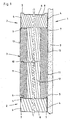
- FIG. 1 illustrated building wall 1 consists of at least several side by side vertically erected profiles 2, of which in FIG. 1 two adjacently arranged profiles 2 are shown. Between the profiles 2 an insulating layer 3 is arranged, which will be described in more detail below.
- Each profile 2 is C-shaped in cross-section and has two mutually parallel legs 4 and a leg 4 connecting, perpendicular to the legs 4 aligned web 5, which has a bead 6 in its central region for stiffening.
- legs 4 At the free ends of the legs 4 bends 7 are arranged, which are aligned with each other.
- the space between the legs 4 on the one hand and the bends 7 and the web 5 on the other hand is filled with a profile body 8 of insulating material, namely mineral fibers.
- Profiles 2 are aligned in the same orientation, so that the insulating layer 3 on the one hand to the profile body 8 in the region of the bends 7 and on the other hand, ie in the region of the second profile 2 on the outer surface of the web 5 connects.
- the insulating layer 3 is clamped between the outside of the web 5 and the profile body 8 of the adjacent profile 2.
- the building wall 1 also has two panels 9, of which in FIG. 1 only a panel 9 is shown, which is connected by screws not shown with the legs 4 adjacent profiles 2, wherein the panel 9 consists of several cladding elements, such as plasterboard.
- the insulating layer 3 consists of a mineral fiber body 10, which is divided into a plurality of insulating boards, which are arranged one above the other between adjacent profiles 2.
- the mineral fiber body has three layers 11 and 12, wherein the two outer layers 11 made of rock wool and the middle layer 12 consists of glass wool.
- the middle layer 12 has compared to the two outer layers 11 has a lower bulk density and a lower dynamic stiffness, so that it is designed to be compressible overall, with their compressibility provided both in the direction of the surface normal of the large surfaces 13 of the insulating layer 3 and at right angles thereto is.
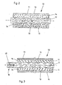
- the mineral fiber body 10 is otherwise in the FIG. 2 shown in longitudinal section in the uninstalled state.
- the middle layer 12 has a laminar fiber profile, ie, the mineral fibers of the middle layer 12 are aligned substantially parallel to the large surfaces 13 of the mineral fiber body 10.
- the mineral fibers of the outer layers 11 may also be aligned parallel to the large surfaces 13 or at right angles to the large surfaces 13.
- the strength properties of the mineral fiber body 10 are substantially determined.
- the middle layer 12 projects beyond the longitudinal sides 14 of the outer layers 11, the middle layer 12 projecting further in the region of one longitudinal side 14 than in the region of the opposite longitudinal side 14 of the outer layers 11.
- This embodiment has the advantage that that, for example, the space in the region of the bead 6 or the space of a displaced profile body 8 is filled by the compressible middle layer 12, so that no cavities remain, which may adversely affect the heat and / or sound insulation properties of the insulation layer 3.
- FIG. 3 a further embodiment of a mineral fiber body 10 is shown, which in addition to the embodiment according to FIG. 2 on both large surfaces 13 of the outer layers 11 has a lamination 15 of a bound and cured with at least one organic and inorganic binder fiber flour.
- the lamination 15 has a bulk density of 300 kg / m 3 and a layer thickness of 10 mm.
- the middle layer 12 of the embodiment according to FIG. 3 has in its projecting beyond the longitudinal side portion 16 a in the longitudinal direction of the middle layer 12, extending over the entire length of the mineral fiber body 10 recess 17, which is T-shaped in cross section.
- the mineral fiber body 10 is inserted with the section 16 in a profile 2 between the legs 4 instead of the profile body 8, so that the compressible middle layer 12 changes in shape such that the portion 16 at least approximately completely fills the space between the legs 4 ,
- the recess 17 is provided, which allows a central division of the portion 17, so that the two formed by the recess 17 halves of the portion 16 deform on both sides of the recess 17.
- the T-shaped configuration of the recess 17 in this case prevents a fraction of the portion 16, wherein the both sides of the transverse end of the recess 17 arranged fiber regions assume the function of a joint and allow the folding away of the two halves of the section 16.
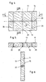
- FIGS. 4 to 6 show an outer layer 11 in the form of an insulating board.
- the layer 11 has in the region of its surfaces 13 elasticized portions 20. In these subregions, the surface 13 of the layer 11 is mechanically stressed by a milling process, so that the individual mineral fibers are dissolved in their bond to each other and partially broken.
- the layer 11 according to the FIGS. 4 to 5 has in this regard a portion 20 which extends parallel to the longitudinal extent of the layer 11 over the entire length of the layer 11 and is arranged in the center axis plane of the layer 11.
- the layer 11 has three transverse to the longitudinal extent extending portions 20, of which the central portion in the central region of the layer 11 and the two outer portions are arranged at a uniform distance from the central portion 20.
- the elasticized portions 20 extend according to the FIGS. 5 and 6 over the entire material thickness of the layer 11 and serve to increase the compressibility of the layer 11 in the direction of the subregions.
- the layer 11 in the direction of the section according to FIG. 5 a high longitudinal stiffness and in the direction of the cut according to FIG. 6 a low longitudinal stiffness, so that according to the number of elasticized portions 20 a uniform compressibility of the layer 11 is given.
Abstract
Description
Die Erfindung betrifft eine Mineralfaser-Dämmschicht aus aneinanderliegenden Dämmplatten, die zwischen zwei beabstandet zueinander angeordneten Gebäudeteilen einbaubar sind, wobei jede Dämmplatte aus einem Mineralfaserkörper mit zwei großen parallel zueinander ausgerichteten, an den Gebäudebauteilen anlegbaren Oberflächen und diese verbindende Seitenflächen besteht. Darüber hinaus betrifft die Erfindung eine Gebäudewand mit einem Stützgerüst, bestehend aus zumindest zwei im Abstand zueinander angeordneten, vorzugsweise lotrecht ausgerichteten Ständern, insbesondere in Form von G, U-, W- oder Ω förmigen Profilen aus Metall, einer zumindest einseitigen Verkleidung, vorzugsweise in Form von Gipskarton- und/oder Gipsfaser-Platten und einer Wärme- und/oder Schalldämmung aus einer Dämmschicht mit zwei großen Oberflächen.The invention relates to a mineral fiber insulating layer of adjacent insulating panels, which are installed between two spaced-apart building parts, wherein each insulating board consists of a mineral fiber body with two large parallel aligned, can be applied to the building components surfaces and these connecting side surfaces. Moreover, the invention relates to a building wall with a scaffold, consisting of at least two mutually spaced, preferably vertically oriented uprights, in particular in the form of G, U, W or Ω-shaped profiles made of metal, an at least one-sided panel, preferably in Form of plasterboard and / or gypsum fiberboards and a thermal and / or acoustic insulation consisting of an insulating layer with two large surfaces.
Aus dem Stand der Technik sind Gebäudewände und in diesen eingebaute Dämmschichten bekannt. Es handelt sich hierbei um nicht tragende innere Wände, die als Trennwände mit Flächengewichten bis zu 1,5 kN/m2 ausgebildet sind und im Unterschied zu aus Ziegeln, Steinen oder Porenbetonelementen unter Verwendung von Mörteln oder Klebermassen aufgebauten Wandkonstruktionen Montagewände genannt werden. Diese Namensgebung beschreibt bereits das Zusammenfügen der Komponenten im trockenen Zustand (Trockenbau) im Zuge einer Montage der einzelnen Komponenten.From the prior art building walls and built-in insulating layers are known. These are non-load-bearing inner walls, which are designed as dividing walls with basis weights of up to 1.5 kN /
Gattungsgemäße Gebäudewände werden überwiegend durch ihr Eigengewicht beansprucht und sind nicht in das statische Konzept eines Gebäudes integriert. Sie müssen allerdings auf ihre Fläche wirkende Kräfte aufnehmen und in die angrenzenden tragenden Bauteile einleiten. Verformungen der angrenzenden Bauteile dürfen nicht zu Zwängungsspannungen in den nicht tragenden Gebäudewänden führen, so dass diese Gebäudewände durch Bewegungsfugen von den angrenzenden Bauteilen zu trennen sind.Generic building walls are mainly claimed by their own weight and are not integrated into the static concept of a building. However, they must absorb forces acting on their surface and introduce them into the adjacent supporting components. Deformations of the adjacent components must not lead to constrained stresses in the non-load-bearing building walls, so that these Building walls are separated by movement joints of the adjacent components.
Gattungsgemäße Gebäudewände müssen bestimmte Anforderungen hinsichtlich des Schall-, Wärme- und Brandschutzes erfüllen. Insbesondere sollen hierbei hohe Schalldämmeigenschaften und zumindest eine Feuenividerstandsklasse F 30 nach DIN 4102 Teil 4 erzielt werden. Es sind aber auch Gebäudewände bekannt, die aufgrund entsprechender Feuerschutzkonstruktionen bis zu 180 Minuten einer Brandbeanspruchung widerstehen können und demzufolge als feuerbeständig mit einer entsprechend höheren Klassifizierung der Feuerwiderstandsklassen zu bezeichnen sind. Entsprechende Anforderungen an die Widerstandsfähigkeit der Gebäudewand im Brandfall führen aber dazu, dass bestimmte Baustoffe, insbesondere im Bereich der tragenden Konstruktionselemente nicht verwendet werden dürfen, wenn diese Baustoffe im Feuer ihre Standfestigkeit verlieren oder einen aktiven Beitrag zum Brandgeschehen leisten.Generic building walls must meet certain requirements in terms of sound, heat and fire protection. In particular, high sound insulation properties and at least one fire resistance class F 30 according to DIN 4102 Part 4 should be achieved. But there are also known building walls, which can withstand up to 180 minutes of fire stress due to appropriate fire protection structures and are therefore to be described as fire resistant with a correspondingly higher classification of the fire resistance classes. However, corresponding requirements for the resistance of the building wall in case of fire lead to the fact that certain building materials, especially in the field of load-bearing construction elements may not be used if these materials in the fire lose their stability or make an active contribution to the fire.
Hier in Rede stehende Gebäudewände, die aus metallischen Ständern und Gipskartonplatten bestehen, werden in DIN 18 183 beschrieben. Es wird zwischen Einfach- und Doppelständerwänden, sowie freistehenden Vorsatzschalen unterschieden. Nach der DIN 18 183 besteht eine Einfachständerwand aus einer in einer Ebene angeordneten Unterkonstruktion mit Ständern, die beidseitig mit Gipskartonplatten als Verkleidung beplankt sind. Bei der Doppelständerwand sind die Ständer in zwei parallelen Ebenen angeordnet und nur auf den beiden äußeren Seiten mit einer Verkleidung aus Gipskartonplatten beplankt. Freistehende Vorsatzschalen bestehen aus einer in einer Ebene angeordneten Unterkonstruktion mit Ständern und einer einseitigen Verkleidung aus Gipskartonplatten.Building walls in question, which consist of metallic uprights and plasterboard, are described in DIN 18 183. There is a distinction between single and double column walls, as well as freestanding facing shells. According to DIN 18 183, a single stud wall consists of a substructure arranged in a single plane with uprights covered with gypsum plasterboard panels on both sides. In the double column wall, the stands are arranged in two parallel planes and only covered on the two outer sides with a plasterboard cladding. Freestanding facing shells consist of a substructure with uprights arranged in one level and a one-sided cladding made of plasterboard.
Die Ständer werden nach ihrer Profilierung als C- oder U-Profile bezeichnet, wobei sich die C-Profile dadurch von den U-Profilen unterscheiden, dass die freien Enden ihrer Schenkel einfach oder doppelt aufeinander zu umbördelt sind. Ergänzend werden die Buchstaben "W oder "D" an die Buchstaben "C" bzw. "U" angehängt, wenn die Profile als Wandprofile (W) oder Deckenprofile (D) Verwendung finden. Die Umbördelung der freien Enden der Stege dient der Aussteifung der Profile, die alternativ oder ergänzend auch durch Sicken im Bereich des Steges oder aber auch im Bereich der Schenkel erzielt werden kann. Durch die Sicken wird ergänzend eine geringere Anlagefläche an den Verkleidungselementen erzielt, so dass sich die Schallenergie im Bereich der Kontaktflächen zwischen Verkleidung und Profil verringert. Alternativ können auf den Schenkeln außenseitig punktförmige Erhebungen angeordnet sein, um eine Distanz zwischen den Schenkeln und den Verkleidungselementen einzustellen.The stands are referred to their profile as C or U-profiles, whereby the C-profiles differ from the U-profiles in that the free ends of their legs are simply or twice flanged to each other. In addition, the letters "W" or "D" are appended to the letters "C" or "U" if the profiles are used as wall profiles (W) or ceiling profiles (D) Profiles which can alternatively or additionally also be achieved by corrugations in the region of the web or else in the region of the legs Contact surfaces between cladding and profile reduced. Alternatively, punctiform projections may be arranged on the legs on the outside in order to set a distance between the legs and the cladding elements.
Im Bereich der Sicken können darüber hinaus Kabel verlegt werden.Cables can also be laid in the area of the beads.
Die Profile werden auf dem Boden oder an der Decke mit Hilfe von eingedübelten Schrauben oder durch Drehstiftdübel befestigt. Die Drehstiftdübel trennen hierbei über eine zylindrische Kunststoffhülse den metallischen Kern von dem Profil, um die Weiterleitung von Körperschall zu reduzieren. Im Brandfall fixiert der Metallstift das Profil und damit die Gebäudewand auch dann noch, wenn der Kunststoff geschmolzen oder verbrannt ist. Vorzugsweise beträgt der Abstand zwischen den einzelnen Befestigungspunkten ca. einen Meter. In einer Gebäudewand ist üblicherweise ein Profil auf dem Boden und ein Profil an der Decke gegenüberliegend angeordnet, so dass sich eine lotrecht ausgerichtete Gebäudewand bereits dann ergibt, wenn die Verkleidungselemente an einem Schenkel des Deckenprofils und dem gegenüberliegenden Schenkel des Bodenprofils befestigt werden.The profiles are fixed to the floor or to the ceiling with the help of doweled screws or through dowel pins. The swivel dowels separate the metallic core from the profile via a cylindrical plastic sleeve in order to reduce the transmission of structure-borne noise. In case of fire, the metal pin fixes the profile and thus the building wall even if the plastic is melted or burnt. Preferably, the distance between the individual attachment points is about one meter. In a building wall, a profile is usually arranged on the floor and a profile on the ceiling opposite, so that a vertically aligned building wall already results when the cladding elements are attached to a leg of the ceiling profile and the opposite leg of the floor profile.
Zwischen den am Boden und an der Decke befestigten Profilen und den angrenzenden Bauteilen, beispielsweise dem Boden und der Decke müssen Dichtelemente eingesetzt sein, um sowohl einen schalldichten Abschluss als auch einen gegen Feuer und Rauch weitgehend dichten Abschluss zwischen den angrenzenden Bauteilen und der Gebäudewand aufzubauen. Entsprechende Dichtungen müssen kompressibel ausgebildet sein, um Unebenheiten der angrenzenden Bauteile bis zu einem gewissen Grad ausgleichen zu können. Demzufolge können sowohl kompressible Dichtbänder aus Schaumstoffen, Kitten oder sehr häufig Streifen aus Mineralwolle-Dämmstoffen in Dicken von ca. 10 bis ca. 20 mm eingesetzt werden.Sealing elements must be used between the profiles fixed to the floor and the ceiling and the adjacent components, for example the floor and the ceiling, in order to build both a sound-proof finish and a largely watertight seal between the adjacent building components and the building wall. Appropriate seals must be designed to be compressible to compensate for unevenness of the adjacent components to a certain extent. Consequently, both compressible sealing tapes made of foams, kitten or very often strips of mineral wool insulation materials in thicknesses of about 10 to about 20 mm can be used.
In die im Bodenbereich und an der Decke befestigten U-Profile werden lotrecht ausgerichtete Profile, sogenannte Ständerprofile eingesetzt, wobei die Schenkel dieser Ständerprofile in einer Gebäudewand im Wesentlichen eine gleich gerichtete Orientierung aufweisen, d.h., dass die Schenkel der Ständerprofile auf den Steg eines benachbarten Ständerprofils zu ausgerichtet sind. Ist ein Ständerprofil im Bereich eines angrenzenden Bauteils, beispielsweise einer tragenden Wand angeordnet, so wird dieses Ständerprofil in gleicher Weise an der tragenden Wand befestigt, wie die zuvor beschriebenen U-Profile im Bereich von Boden und Decke.In the U-profiles fixed in the floor area and on the ceiling, vertically oriented profiles, so-called stud profiles, are used, the legs of these stud profiles having essentially the same orientation in a building wall, ie the legs of the stud profiles on the web of an adjacent stud profile to be aligned. If a stand profile is arranged in the region of an adjacent component, for example a load-bearing wall, then this stand profile is fastened to the load-bearing wall in the same way as the previously described U-profiles in the area of floor and ceiling.
In der Regel werden die Ständerprofile reibschlüssig in den U-Profilen an Decke und Boden gehalten, wobei die Ständerprofile vom Steg des deckenseitig befestigten U-Profils mit Abstand angeordnet sind, um eine Relativbewegung der Ständerprofile zu den U-Profilen zu ermöglichen. Ergänzend können die Ständerprofile aber durch sogenannte Blindnieten miteinander verbunden werden, wenn Querriegel für Öffnungen oder sonstige Einbauten eingesetzt werden. Im Normalfall werden die Ständerprofile aber durch die Verkleidungselemente mit den deckenseitig und bodenseitig angeordneten U-Profilen fixiert.In general, the upright profiles are frictionally held in the U-profiles on the ceiling and floor, wherein the uprights are spaced from the web of the ceiling-mounted U-profile to allow relative movement of the uprights to the U-profiles. In addition, however, the uprights can be interconnected by so-called blind rivets when crossbars are used for openings or other installations. Normally, however, the upright profiles are fixed by the cladding elements with the U-profiles arranged on the cover side and on the bottom side.
Als Verkleidungselemente werden Gipskartonplatten in den Varietäten Gipskartonbau-(GKB) oder Feuerschutzplatten (GKF) oder Gipsfaserplatten verwendet. Derartige Platten sind mit unterschiedlichen Materialstärken und mit Längen zwischen 2000 und 4000 mm bei einer Abstufung von 250 mm bekannt, wobei die Breite derartiger Platten mit 1250 mm konstant ist. Bei Materialstärken von mehr als 18 mm ist die maximale Länge derartiger Platten auf 3500 mm begrenzt, wobei diese Platten mit Breiten von 600 mm oder 1250 mm angeboten werden. Aufgrund der Abmessungen der Platten und der bevorzugten hochkant ausgerichteten Einbaulage hat sich ein Abstand zwischen benachbarten Ständerprofilen von 62,5 cm als besonders vorteilhaft erwiesen, so dass die Platten mit ihren beiden Längsrändern an zwei Ständerprofilen und ergänzend mit dem Mittelbereich an einem dritten Ständerprofil befestigt sind. Verbunden werden die Platten mit den Ständerprofilen durch Schnellbauschrauben gemäß DIN 18 182, Teil 2 "Zubehör für die Verarbeitung von Gipskartonplatten - Schnellbauschrauben".As cladding elements plasterboard in the varieties gypsum plasterboard (GKB) or fire protection boards (GKF) or gypsum fiber boards are used. Such plates are known with different thicknesses and with lengths between 2000 and 4000 mm in a gradation of 250 mm, the width of such plates with 1250 mm is constant. For material thicknesses greater than 18 mm, the maximum length of such plates is limited to 3500 mm, these plates being offered with widths of 600 mm or 1250 mm. Due to the dimensions of the plates and the preferred upright mounting position, a distance between adjacent column profiles of 62.5 cm has proven to be particularly advantageous, so that the plates are fixed with its two longitudinal edges on two upright profiles and complementary to the central region on a third upright profile , The panels are connected to the frame profiles by drywall screws in accordance with DIN 18 182,
Der Hohlraum zwischen benachbarten Ständerprofilen einerseits und den Verkleidungselementen andererseits wird durch Dämmschichten ausgefüllt, die üblicherweise aus einzelnen Dämmplatten mit großer Steifigkeit bestehen. Diese Dämmplatten werden einerseits zwischen die Schenkel eines Trägerprofils eingeschoben, bis die Schmalseiten der Dämmplatten an dem Steg innenseitig anliegen. Andererseits werden die Dämmplatten mit ihrer gegenüberliegenden Schmalseite an die Außenseite des Steges des benachbarten Ständerprofils angelegt. Das Ausfüllen der Hohlräume mit einzelnen Dämmplatten führt zwar zu hervorragenden Dämmergebnissen, stellt aber aufgrund der Montage der relativ steifen Dämmplatten zwischen den Schenkeln der Trägerprofile eine aufwendige und gegebenenfalls unzureichend durchgeführte Arbeit dar. Vorzugsweise besteht die Dämmschicht aus zumeist leichten Faserdämmstoffen mit geringem längenspezifischen Strömungswiderstand, niedriger dynamischer Steifigkeit (S' in MN/m3) und hohem Schallabsorptionsvermögen. Die Dämmschicht wird klemmend zwischen den Profilen eingebaut.The cavity between adjacent stator profiles on the one hand and the cladding elements on the other hand is filled by insulating layers, which usually consist of individual insulation boards with high rigidity. These insulation boards are inserted on the one hand between the legs of a carrier profile until the narrow sides of the insulation boards bear against the web on the inside. On the other hand, the insulating panels are applied with their opposite narrow side to the outside of the web of the adjacent stand profile. Although the filling of the cavities with individual insulation boards leads to excellent Dämmergebnissen, but due to the installation of relatively stiff insulation boards between the legs of the support profiles is a complex and possibly insufficiently performed work. Preferably, the insulating layer consists of mostly lightweight fiber insulating materials with low length-specific flow resistance, low dynamic stiffness (S 'in MN / m 3 ) and high sound absorption capacity. The insulating layer is installed by clamping between the profiles.
Für die Dämmschicht verwendete Faserdämmstoffe müssen nicht brennbar gemäß DIN 4101 Teil I ausgebildet sein. Überwiegend werden Glaswolle-Dämmfilze, sowie Glaswolle- und/oder Steinwolle-Dämmplatten verwendet. Für Gebäudewände, die Brandschutzkonstruktionen nach DIN 4102 Teil 4 darstellen sollen bzw. eine hohe Feuerwiderstandsklasse haben, werden Steinwolle-Brandschutzplatten mit einem Schmelzpunkt gemäß DIN 4102 Teil 17 ≥ 1000° C in definierten Rohdichten mit zumeist verringerten Anteilen organischer Bindemittel in den entsprechenden Dicken verwendet. Trennwand-, Akustik- und Brandschutzplatten werden üblicherweise mit den Abmessungen 1000 mm X 625 mm angeboten und verarbeitet. Die Rohdichte normaler Akustikplatten beträgt in Abhängigkeit der angestrebten Wärmeleitfähigkeit Ca. 27 bis Ca. 35 kg/m3. Bei Brandschutzplatten liegen die Mindestrohdichten bei 30, 40, 50 oder 100 kglm3, wobei Materialstärken von 40 bis 100 mm eingebaut werden. Die Rohdichten sind hierbei abhängig von den Anforderungen hinsichtlich der Brandsicherheit.Fiber insulating materials used for the insulating layer must not be made flammable in accordance with DIN 4101 Part I. Mostly glass wool insulation felts, and glass wool and / or rock wool insulation boards are used. For building walls that are to represent fire protection structures according to DIN 4102 Part 4 or have a high fire resistance class, rockwool fire protection boards are used with a melting point according to DIN 4102
Die Breiten der Akustikfilze bzw. Dämmplatten stimmen exakt mit den regelmäßigen Abständen der lotrecht verlaufenden Profile überein. Zu berücksichtigen ist, dass die nominellen Breitenmaße der Dämmstoffelemente durch Abmaße verringert sein können. Beispielsweise sieht DIN 18 165 Teil 1 zulässige Abweichungen von den Nennmaßen der Länge und der Breite von ± 2 % vor. Derartige Abweichungen kommen in der Praxis zwar selten und nur bei fehlerhaften Produktionen vor, führen aber bei einer Verwendung dieser Dämmstoffelemente zu einem Fehlen des klemmenden Einbaus der Dämmstoffelemente zwischen den Profilen. Fehlt das hierfür erforderliche Übermaß der Dämmstoffelemente, so entstehen durchlaufende Fugen in der Dämmschicht, die mitunter unentdeckt bleiben und dann zu einer verminderten Wärme- bzw. Schalldämmung führen.The widths of the acoustic felts or insulation panels exactly match the regular intervals of the vertically extending profiles. It should be noted that the nominal width dimensions of the insulating elements may be reduced by dimensions. For example, DIN 18 165
Um die hiermit verbundenen Probleme auszuschließen ist es übliche Praxis, die Dämmstoffplatten quer zur Längsachse abzulängen, d.h. maßgenau auf den Einbau vorzubereiten. Diese Praxis führt aber zu einem zusätzlichen Arbeitsgang des Beschneidens der Platten und zu erheblichen Abfallmengen, da es zumeist nicht gelingt, die einzelnen Abschnitte wieder zu einem funktionierenden Dämmstoffelement der Dämmschicht zusammenzusetzen. Die Dämmstoffelemente werden zwischen die Schenkel der Profile gepreßt. Diese Tätigkeit ist sehr mühsam, weil zum einen evtl. Umkantungen der Schenkel und insbesondere die Schraubenspitzen der bereits einseitig montierten Verkleidung Hindernisse bilden, deren Überwindung darüber hinaus zu Beschädigungen der Dämmschicht, aber auch zu einer nicht unerheblichen Verletzungsgefahr für die Hände der handhabenden Arbeiter darstellen. Andererseits steifen insbesondere die Schrauben aber auch Befestigungselemente für die Dämmschicht dar, soweit die Dämmschicht auf die Schrauben aufgespießt bzw. aufgehängt werden, so dass auch die bereits erwähnten Akustikfilze verwendet werden können. Um die Verletzungsgefahr zu reduzieren, werden diese Arbeiten sehr vorsichtig und somit langsam durchgeführt. Neben dem damit verbundenen geringen Arbeitsfortschritt stellt sich ergänzend auch ein mitunter mit Mängeln behaftetes Arbeitsergebnis dar, wobei die Mängel insbesondere im Bereich der Profile nicht unmittelbar zu erkennen sind.In order to exclude the problems associated therewith, it is common practice to cut the insulation boards transversely to the longitudinal axis, ie to prepare accurately to the installation. However, this practice leads to an additional operation of trimming the plates and to considerable amounts of waste, since it is usually not possible to reassemble the individual sections to form a functioning insulating element of the insulating layer. The insulating elements are between the Legs of the profiles pressed. This activity is very cumbersome, because on the one hand possibly edging of the legs and in particular the screw tips of the already one-sided fairing form obstacles whose overcoming represent beyond damage to the insulating layer, but also to a significant risk of injury to the hands of the handling workers. On the other hand, in particular the screws but also fasteners for the insulating layer stiff, as far as the insulating layer are skewered or hung on the screws, so that even the aforementioned acoustic felts can be used. To reduce the risk of injury, this work is carried out very carefully and thus slowly. In addition to the associated low work progress is in addition also a sometimes fraught with defects work results, the deficiencies are not immediately apparent, especially in the field of profiles.
Bei Abständen zwischen den Profilen, die geringer sind, als die Breiten der Dämmstoffelemente, besteht die Möglichkeit, die in die Profile einzusetzenden Ränder der Dämmstoffelemente aus dünnen und kompressiblen Glaswolle-Platten auszubilden, die aufgrund ihrer Kompressibilität in einfacher Weise umgeschlagen und in die Profile eingedrückt werden können, so dass sich hieraus eine vollständige Ausfüllung des Profils ohne die zuvor beschriebenen Verletzungsrisiken ergibt. Diese Vorgehensweise hat aber hinsichtlich der Anforderungen an die Genauigkeit der Verarbeitung der Dämmstoffelemente Nachteile, da der Kompressionsgrad der einzelnen Dämmstoffelemente, insbesondere Dämmstoffplatten unterschiedlich ist, so dass die Dämmstoffplatten unterschiedlich tief in die Profile eingesteckt werden und gegebenenfalls nicht mehr vollflächig am Steg des gegenüberliegend angeordneten Profils anliegen.At intervals between the profiles, which are smaller than the widths of the insulating elements, it is possible to form the edges of the insulating elements to be used in the profiles of thin and compressible glass wool plates, which easily folded over because of their compressibility and pressed into the profiles can be, so that this results in a complete completion of the profile without the injury risks described above. However, this approach has disadvantages in terms of the requirements for the accuracy of the processing of the insulating elements, since the degree of compression of the individual insulating elements, in particular insulation boards is different, so that the insulation boards are inserted at different depths in the profiles and optionally no longer full surface on the web of the oppositely disposed profile issue.
Nachdem der Hohlraum zwischen den Profilen ausgefüllt ist, wird die Verkleidung ergänzt. Nach dem Verschließen der Gebäudewand mit der auf der zweiten Seite anliegenden Verkleidung liegt die Dämmschicht zumeist in einer zufälligen, selten in der vorgesehenen Position zwischen den Verkleidungselementen, wobei die Dämmplatten in der Regel eine geringere Dicke aufweisen, als der lichte Abstand zwischen den Verkleidungselementen auf den beiden Schenkeln der Profile.After the cavity between the profiles is filled, the cladding is supplemented. After the closure of the building wall with the adjacent to the second side panel, the insulating layer is usually in a random, rarely in the intended position between the cladding elements, the insulation boards usually have a smaller thickness than the clear distance between the cladding elements on the two legs of the profiles.
Eine Mineralfaser-Dämmschicht aus Dämmstoffbahnen oder Dämmplatten ist beispielsweise aus der
Dämmplatte besteht aus einem Mineralfaserkörper mit zwei großen parallel zueinander ausgerichteten, an den Gebäudeteilen anlegbaren Oberflächen und diese verbindende Seitenfläche, wobei der Mineralfaserkörper aus drei sandwichartig angeordneten Schichten aus Mineralfasern besteht.Insulating board consists of a mineral fiber body with two large parallel aligned, can be applied to the building parts surfaces and this connecting side surface, wherein the mineral fiber body consists of three sandwiched layers of mineral fibers.
Darüber hinaus offenbart die
Weiterhin offenbart die
Ferner ist aus der
Es ist die Aufgabe der vorliegenden Erfindung, eine Mineralfaser-Dämmschicht derart weiterzubilden, dass deren Herstellung, insbesondere Montage wesentlich vereinfacht und beschleunigt ist, so dass eine kostengünstige Montage bei gleichzeitig zumindest gleichguten Dämmergebnissen möglich ist.It is the object of the present invention to develop a mineral fiber insulating layer in such a way that their production, in particular assembly essential is simplified and accelerated, so that a cost-effective installation at the same time at least as good Dämmergebnissen is possible.
Als Lösung wird mit der Erfindung eine gattungsgemäße Mineralfaser-Dämmschicht aus Dämmplatten vorgeschlagen, bei der der Mineralfaserkörper aus drei getrennt voneinander ausgebildeten und einbaubaren sandwichartig angeordneten Schichten aus Mineralfasern besteht, von denen die mittlere Schicht eine geringere Rohdichte und/oder dynamische Steifigkeit als die beiden äußeren Schichten hat und wobei zumindest die mittlere Schicht einen laminaren Faserverlauf aufweist, das heißt, dass die Mineralfasern im Wesentlichen parallel zu den großen Oberflächen des Mineralfaserkörpers ausgerichtet sind.As a solution , the invention proposes a generic mineral fiber insulating layer of insulating boards, in which the mineral fiber body consists of three separately formed and installed sandwich-like layers of mineral fibers, of which the middle layer has a lower bulk density and / or dynamic stiffness than the two outer Has layers and wherein at least the middle layer has a laminar fiber profile, that is, that the mineral fibers are aligned substantially parallel to the large surfaces of the mineral fiber body.
Die erfindungsgemäße Dämmschicht besteht somit aus zumindest drei Schichten, die flächig übereinander angeordnet sind, wobei die Schichten eine unterschiedliche Rohdichte und/oder dynamische Steifigkeit aufweisen. Vorzugsweise ist vorgesehen, dass der Mineralfaserkörper aus drei Schichten besteht, von denen die mittlere Schicht eine geringere Rohdichte und/oder dynamische Steifigkeit hat, als die beiden äußeren Schichten. Der Mineralfaserkörper und somit die Dämmschicht weist somit im Bereich der mittleren Schicht eine hohe Kompressibilität und Biegbarkeit auf, während die beiden äußeren Schichten eine demgegenüber höhere Steifigkeit haben, die somit bei einem bestimmten Übermaß der Dämmschicht vollflächig und fest an einer Verkleidung einer Gebäudewand anliegen. Die Dämmschichtdicke zwischen den Verkleidungselementen wird somit ausschließlich über die kompressible mittlere Schicht auf den Abstand zwischen den beiden benachbarten Verkleidungen eingestellt.The insulating layer according to the invention thus consists of at least three layers, which are arranged one above the other flatly, wherein the layers have a different bulk density and / or dynamic rigidity. It is preferably provided that the mineral fiber body consists of three layers, of which the middle layer has a lower bulk density and / or dynamic stiffness, than the two outer layers. The mineral fiber body and thus the insulating layer thus has in the middle layer a high compressibility and flexibility, while the two outer layers have a contrast higher stiffness, which thus rest at a certain excess of the insulating layer over the entire surface and fixed to a panel of a building wall. The insulating layer thickness between the cladding elements is thus adjusted exclusively via the compressible middle layer to the distance between the two adjacent cladding.
Vorzugsweise besteht der Mineralfaserkörper aus mehreren, mit ihren Schmalseiten aneinander liegenden Dämmplatten, die beispielsweise nacheinander zwischen Profilen von Ständerwände eingebaut werden. Hierbei können die Dämmplatten eine Materialstärke aufweisen, die im Wesentlichen mit dem Abstand der Verkleidungen übereinstimmt. Ist der Abstand der Verkleidungen jedoch größer als die Materialstärke der Dämmplatten bzw. der Dämmschicht, so können zwei oder mehr Dämmplatten oder andere Dämmelemente zur Bildung der Dämmschicht nebeneinander liegend eingebaut werden.Preferably, the mineral fiber body consists of several, with their narrow sides adjacent insulation boards, which are installed, for example, successively between profiles of stud walls. Here, the insulation boards may have a material thickness that substantially coincides with the distance of the panels. However, if the distance between the cladding is greater than the material thickness of the insulating boards or the insulating layer, two or more insulating boards or other insulating elements can be installed side by side to form the insulating layer.
Nach einem weiteren Merkmal der Erfindung ist vorgesehen, dass die beiden äußeren Schichten unterschiedliche Rohdichten und/oder Materialstärken aufweisen. DieseAccording to a further feature of the invention, it is provided that the two outer layers have different densities and / or material thicknesses. These
Ausgestaltung ermöglicht eine weitere Anpassung der Dämmschicht an die anwendungsspezifisch erforderlichen Eigenschaften.Design allows further adaptation of the insulating layer to the application-specific properties required.
Es ist ferner vorgesehen, dass die Schichten in Teilbereichen elastifiziert ausgebildet sind, um eine richtungsabhängige Steifigkeit der Dämmschicht bzw. der die Dämmschicht bildenden Dämmelemente einzustellen. Die Teilbereiche sind insbesondere in Längs- und/oder Querrichtung der Schichten verlaufend ausgebildet. Ergänzend kann vorgesehen sein, dass sich die Teilbereiche über die gesamte Materialstärke der Schichten erstrecken.It is further provided that the layers are made elasticized in partial areas in order to set a direction-dependent stiffness of the insulating layer or the insulating layer forming the insulating elements. The subregions are designed to extend in particular in the longitudinal and / or transverse direction of the layers. In addition, it can be provided that the subregions extend over the entire material thickness of the layers.
Vorzugsweise sind die Teilbereiche streifenförmig ausgebildet und erstrecken sich nach einem weiteren vorteilhaften Merkmal über die gesamte Breite und/oder Länge der Schichten.Preferably, the subregions are strip-shaped and, according to a further advantageous feature, extend over the entire width and / or length of the layers.
Nach einem weiteren Merkmal der Erfindung ist vorgesehen, dass zumindest eine Schicht in einer Oberfläche mehrere Ausnehmungen aufweiset, die mit zähhartem bis sprödem Material, insbesondere mit Mörtel, vorzugsweise Klebemörtel ausgefüllt sind. Durch diese Ausgestaltung wird die Querzugsfestigkeit entsprechender Dämmschichten variiert.According to a further feature of the invention, it is provided that at least one layer in a surface has a plurality of recesses which are filled with tough to brittle material, in particular with mortar, preferably adhesive mortar. This configuration varies the transverse tensile strength of corresponding insulating layers.
Vorzugsweise sind die Ausnehmungen rund ausgebildet und können nach einem weiteren Merkmal der Erfindung in einem regelmäßigen Raster oder reihenweise versetzt angeordnet sein.Preferably, the recesses are round and can be arranged offset according to a further feature of the invention in a regular grid or in rows.
Es hat sich ferner als vorteilhaft erwiesen, die Schichten vorzugsweise durch ihre Mineralfaserausrichtung mit in Längsrichtung und Querrichtung unterschiedlichen Festigkeitseigenschaften, insbesondere Biegezugfestigkeiten und Steifigkeiten auszubilden. Beispielsweise können die Schichten derart angeordnet sein, dass sie entsprechend ihren Festigkeitseigenschaften gleichgerichtet oder rechtwinklig zueinander ausgerichtet sind. Hierdurch können gezielt die Eigenschaften der Dämmschicht auf den entsprechenden Anwendungsfall angepasst werden.It has also proven to be advantageous to form the layers preferably by their mineral fiber orientation with different in the longitudinal direction and transverse strength properties, in particular bending tensile strengths and stiffnesses. For example, the layers may be arranged such that they are rectified or oriented at right angles to each other according to their strength properties. As a result, the properties of the insulating layer can be specifically adapted to the corresponding application.
Es hat sich als vorteilhaft erwiesen, die beiden äußeren Schichten aus Steinwolle und die mittlere Schicht aus Glaswolle auszubilden, um ein geeignetes Dämmelement auszubilden, mit dem ein Dickenausgleich optimal möglich ist.It has proven to be advantageous to form the two outer layers of rock wool and the middle layer of glass wool in order to form a suitable insulating element with which a thickness compensation is optimally possible.
Zumindest die mittlere Schicht weist einen laminaren Faserverlauf auf, um eine hohe Kompressibilität in Richtung der Flächennormalen der großen Oberflächen des Dämmelementes zu ermöglichen.At least the middle layer has a laminar fiber profile in order to enable high compressibility in the direction of the surface normal of the large surfaces of the insulating element.
Wie bereits erwähnt ist es vorteilhaft, die Gesamtdicke der Schichten größer auszubilden als den Abstand der beiden parallelen Schenkel des Profils, zwischen denen die Dämmschicht einzubringen ist. Die äußeren Schichten liegen bei einer solchen Ausgestaltung fest an den Verkleidungselementen an. Hieraus resultiert eine Verminderung der Schwingungsfähigkeit der Dämmschicht, so dass die Schalldämmung einer hiermit ausgebildeten Gebäudewand wesentlich verbessert, d.h. erhöht ist.As already mentioned, it is advantageous to make the total thickness of the layers greater than the distance between the two parallel legs of the profile, between which the insulating layer is to be introduced. The outer layers are in such an embodiment firmly on the cladding elements. This results in a reduction of the vibration capability of the insulating layer, so that the sound insulation of a building wall formed therewith substantially improved, i. is increased.
Unterschiedliche dynamische Steifigkeiten in verschiedenen Zonen einer Dämmschicht lassen sich durch eine künstliche Elastifizierung von Platten mit zunächst homogener Struktur erreichen. Zu diesem Zweck wird eine der großen Oberflächen in vorteilhafter Weise mehrfach mit Walzen kleinen Durchmessers überrollt, was zu hohen linearen, insbesondere aber Scherbeanspruchungen in der Oberfläche führt. Die Struktur der Dämmplatte wird dadurch bis zu der gewünschten Tiefe zerwalkt, so dass die dynamische Steifigkeit deutlich reduziert wird.Different dynamic stiffnesses in different zones of an insulating layer can be achieved by an artificial elastification of plates with initially homogeneous structure. For this purpose, one of the large surfaces is advantageously rolled over several times with rolls of small diameter, which leads to high linear, but in particular shear stresses in the surface. As a result, the structure of the insulating board is unwrapped to the desired depth, so that the dynamic rigidity is significantly reduced.
Dämmplatten aus Mineralfasern weisen in der Regel über ihre großen Oberflächen weitgehend gleichmäßige, wenn auch richtungsabhängig unterschiedlich hohe Festigkeitseigenschaften auf. Insbesondere bei derartigen Dämmelementen aus Steinwolle sind diese richtungsabhängigen Unterschiede der Festigkeitseigenschaften zu beobachten. Dämmelemente aus Steinwolle werden in an sich bekannter Weise dadurch hergestellt, dass die aus einer silikatischen Schmelze gewonnenen Mineralfasern zunächst in Form eines dünnen Vlieses, einem sogenannten Primärvlies gesammelt und anschließend einer pendelnden Fördereinrichtung zugeführt werden. Das Primärvlies wird mit pendelnden Bewegungen dieser Fördereinrichtung auf einem Bandförderer abgelegt und auf diesem zu einer endlosen Mineralfaserbahn zusammengeschoben. Eine hierbei vorgenommene Längskompression der abgelegten Faserbahn, die auch als Sekundärvlies bezeichnet wird, führt zu einer unterschiedlichen Anordnung der Mineralfasern quer zur Förderrichtung und in Längsrichtung des Sekundärvlieses. Quer zur Förderrichtung ist die Biegezugfestigkeit und die Steifigkeit des Sekundärvlieses deutlich höher als in Längsrichtung, d.h. in Förderrichtung. Hieraus ergeben sich auch richtungsabhängige schalltechnische Eigenschaften der hieraus hergestellten Mineralfaserdämmelemente.As a rule, insulating boards made of mineral fibers have largely uniform, if dependent on the direction, different strength properties over their large surfaces. In particular, in such insulation elements made of rock wool, these directional differences in the strength properties are observed. Rock wool insulation elements are produced in a manner known per se by collecting the mineral fibers obtained from a silicate melt first in the form of a thin fleece, a so-called primary fleece, and then feeding them to a swinging conveying device. The primary fleece is deposited with oscillating movements of this conveyor on a belt conveyor and pushed together on this to an endless mineral fiber web. A longitudinal compression of the deposited fibrous web, which is also referred to as a secondary nonwoven, results in a different arrangement of the mineral fibers transversely to the conveying direction and in the longitudinal direction of the secondary nonwoven. Transverse to the conveying direction, the bending tensile strength and the stiffness of the secondary web is significantly higher than in the longitudinal direction, ie in the conveying direction. This also results in directional acoustic properties of the mineral fiber insulation elements produced therefrom.
Die Steifigkeit der Mineralfaserdämmelemente wird durch eine Lockerung der Bindung der einzelnen Fasern untereinander verändert. Beispielsweise kann durch einen Walkvorgang örtlich hoher Druck auf die Mineralfasern ausgeübt werden, wodurch die Verbindung zwischen einzelnen Mineralfasern gelockert und die Mineralfasern selbst gebrochen oder umgelagert werden. Das Resultat dieser Vorgehensweise ist eine Elastifizierung der Mineralfaserbahn. Hieraus hergestellte Mineralfaserdämmelemente werden durch diese Vorgehensweise kompressibler bzw. leichter biegbar gemacht.The rigidity of Mineralfaserdämmelemente is changed by relaxing the binding of the individual fibers with each other. For example, locally high pressure can be exerted on the mineral fibers by a waving process, whereby the connection between individual mineral fibers is loosened and the mineral fibers themselves are broken or rearranged. The result of this procedure is an elastification of the mineral fiber web. Mineral fiber insulation elements made from this are made more compressible or easier to bend by this procedure.
Hiermit einhergehend ist aber auch eine Veränderung der schalltechnischen Eigenschaften dieser Mineralfaserdämmelemente, die in Wandkonstruktionen einbaubar sind. Der Vorteil dieser Mineralfaserdämmstoffe liegt aber nunmehr darin, dass durch die örtlich unterschiedlichen dynamischen Steifigkeiten bzw. unterschiedlichen Schalldämpfungseigenschaften anwendungsfallspezifische Dämmschichten herstellbar sind. Hierbei erfolgt die Elastifizierung insbesondere quer zu der Richtung der größten Steifigkeit der Mineralfaserdämmelemente.Along with this, however, there is also a change in the acoustic properties of these Mineralfaserdämmelemente that can be installed in wall constructions. However, the advantage of these mineral fiber insulating materials lies in the fact that application-specific insulating layers can be produced by the locally different dynamic stiffnesses or different sound damping properties. In this case, the elastification takes place in particular transversely to the direction of the greatest rigidity of Mineralfaserdämmelemente.
Bei zweischichtigen Dämmschichten, die außen eine höhere und innen eine geringere Rohdichte aufweisen, können die Dämmelemente durch eine entsprechende Formgebung der aneinander grenzenden Oberflächen rein mechanisch zusammengefügt sein.In the case of two-layer insulating layers, which have a higher density on the outside and a lower density on the inside, the insulating elements can be joined together purely mechanically by appropriate shaping of the adjoining surfaces.
Die einzelnen Schichten der Dämmschicht werden getrennt voneinander eingebaut.The individual layers of the insulating layer are installed separately.
Nach einem weiteren Merkmal der Erfindung ist vorgesehen, dass die mittlere Schicht eine im Vergleich zu den äußeren Schichten größere Länge aufweist und insbesondere im Bereich einer, vorzugsweise beider Schmalseiten(n) in Längsrichtung über die äußeren Schichten hervorsteht. Eine derart ausgebildete Dämmschicht hat den Vorteil, dass beim Einbau der Dämmschicht zwischen die Schenkel des Profils der von der mittleren Schicht hervorstehende Bereich innerhalb des Raumes zwischen den Schenkels des Profils komprimiert wird und diesen Raum folglich ausfüllt, so dass ein dichtes Anliegen der weniger kompressiblen äußeren Schichten vollflächig an dem Profil möglich ist.According to a further feature of the invention, it is provided that the middle layer has a greater length compared to the outer layers and protrudes in the longitudinal direction over the outer layers in particular in the region of one, preferably both narrow sides (n). Such a formed insulating layer has the advantage that when installing the insulating layer between the legs of the profile of the protruding from the middle layer area is compressed within the space between the leg of the profile and thus fills this space, so that a dense concern the less compressible outer Layers over the entire surface of the profile is possible.
Hierzu hat es sich als vorteilhaft erwiesen, wenn die mittlere Schicht eine in Längsrichtung und/oder zumindest eine rechtwinklig dazu verlaufende Ausnehmung aufweist, so dass die mittlere Schicht beispielsweise in zwei Abschnitte geteilt ist, die sich beim Kompression in entgegengesetzte Richtungen bewegen lassen, um den Raum zwischen den Schenkeln des Profils vollständig auszufüllen. Vorzugsweise ist die Ausnehmung im Querschnitt T-förmig ausgebildet, so dass sie eine Art Sacklochöffnung bildet und ein Abscheren der beiden Abschnitte der mittleren Schicht bei der Kompression innerhalb des Profils vermieden wird. Die Überstände der mittleren Schicht sind vorzugsweise unterschiedlich ausgebildet, um zum einen eine Markierung anzugeben, mit welcher Schmalseite die Dämmschicht innerhalb des Profils anzuordnen ist und welche Schmalseite an der außenliegenden Fläche des Stegs des gegenüberliegenden Profils anliegt und zum anderen den unterschiedlichen Bedingungen gerecht zu werden, die zwischen den Schenkeln und bei der Anlage an der Außenfläche des Stegs bestehen. Alternativ zu einem Überstand der mittleren Schicht kann vorgesehen sein, dass die Bereiche an den Längs- und/oder Schmalseiten des Mineralfaserkörpers insbesondere durch Stauchen elastifiziert sind. Durch diese Elastifizierung wird die Kompressibilität der äußeren Schichten derart erhöht, dass ein Eindrücken der Dämmschicht zwischen die Schenkel des Profils wesentlich vereinfacht ist und gleichzeitig die Dämmschicht mit Übermaß im Vergleich zum Abstand benachbarter Profile ausgebildet und klemmend eingebaut werden kann.For this purpose, it has proved to be advantageous if the middle layer has a longitudinally extending and / or at least a perpendicular thereto recess, so that the middle layer is divided, for example, into two sections which can be moved in compression in opposite directions to the Space between completely fill the legs of the profile. Preferably, the recess is T-shaped in cross section, so that it forms a kind of blind hole opening and shearing of the two sections of the middle layer is avoided during the compression within the profile. The supernatants of the middle layer are preferably formed differently in order to indicate a mark with which narrow side the insulating layer is to be arranged within the profile and which narrow side rests against the outer surface of the web of the opposite profile and on the other to meet the different conditions, which exist between the legs and at the plant on the outer surface of the web. As an alternative to a projection of the middle layer, provision may be made for the regions on the longitudinal and / or narrow sides of the mineral fiber body to be elasticized, in particular by upsetting. By this elastification, the compressibility of the outer layers is increased so that a depression of the insulating layer between the legs of the profile is substantially simplified and at the same time the insulating layer formed with excess compared to the distance between adjacent profiles and can be installed by clamping.
Vorzugsweise weisen die äußeren Schichten eine Rohdichte von 200 bis 600 kg/m3 auf. Nach einem weiteren Merkmal der Erfindung ist vorgesehen, dass die äußeren Schichten eine Schichtdicke von 3 bis 20 mm haben.The outer layers preferably have a bulk density of 200 to 600 kg / m 3 . According to a further feature of the invention, it is provided that the outer layers have a layer thickness of 3 to 20 mm.
Hinsichtlich einer gattungsgemäßen Gebäudewand wird mit der Erfindung die Ausbildung der Dämmschicht nach einem der Ansprüche 1 bis 22 vorgeschlagen.With regard to a generic building wall, the invention proposes the formation of the insulating layer according to one of
Sämtliche voranstehend diskutierten Merkmale der erfindungsgemäßen Dämmschicht können bei einer erfindungsgemäßen Gebäudewand vorgesehen sein und bilden diese erfindungsgemäß weiter.All of the above-discussed features of the insulating layer according to the invention can be provided in a building wall according to the invention and form these further according to the invention.
Bezüglich der Vorteile und der weiteren Ausgestaltungen der erfindungsgemäßen Gebäudewand, insbesondere im Hinblick auf die entsprechenden Merkmale der Unteransprüche, wird sowohl auf die voranstehende Beschreibung der Vorteile der Dämmschicht, als auch auf die nachfolgende Beschreibung der zugehörigen Zeichnung verwiesen, in der bevorzugte Ausführungsformen einer Dämmschicht dargestellt sind. In der Zeichnung zeigen:
Figur 1- eine Gebäudewand in geschnitten dargestellter Draufsicht;
Figur 2- ein Dämmelement einer Dämmschicht der Gebäudewand gemäß
Figur 1 ; Figur 3- eine weitere Ausführungsform eines Dämmelementes einer Dämmschicht der Gebäudewand gemäß
Figur 1 ; - Figur 4
- eine äußere Schicht eines Dämmelementes nach
Figur 3 in Draufsicht; Figur 5- die äußere Schicht gemäß
Figur 4 in einer geschnittenen Seitenansicht entlang der Linie VII-VII inFigur 4 ; Figur 6- die äußere Schicht gemäß
Figur 4 in einer geschnitten dargestellten Seitenansicht entlang der Linie VIII-VIII inFigur 4 ;
- FIG. 1
- a building wall in a sectional plan view;
- FIG. 2
- an insulating element of an insulating layer of the building wall according to
FIG. 1 ; - FIG. 3
- a further embodiment of an insulating element of an insulating layer of the building wall according to
FIG. 1 ; - FIG. 4
- an outer layer of an insulating element after
FIG. 3 in plan view; - FIG. 5
- the outer layer according to
FIG. 4 in a sectional side view along the line VII-VII inFIG. 4 ; - FIG. 6
- the outer layer according to
FIG. 4 in a sectional side view taken along the line VIII-VIII inFIG. 4 ;
Eine in
Jedes Profil 2 ist im Querschnitt C-förmig ausgebildet und hat zwei parallel zueinander verlaufende Schenkel 4 und einen die Schenkel 4 verbindenden, zu den Schenkeln 4 rechtwinklig ausgerichteten Steg 5, der in seinem Mittelbereich eine Sicke 6 zur Aussteifung hat. An den freien Enden der Schenkel 4 sind Abbiegungen 7 angeordnet, die aufeinanderzu ausgerichtet sind. Der Raum zwischen den Schenkeln 4 einerseits und den Abbiegungen 7 sowie dem Steg 5 andererseits ist mit einem Profilkörper 8 aus Dämmmaterial, nämlich Mineralfasern ausgefüllt.Each
Es ist zu erkennen, dass die beiden in
Die Gebäudewand 1 weist ferner zwei Verkleidungen 9 auf, von denen in
Die Dämmschicht 3 besteht aus einem Mineralfaserkörper 10, der in mehrere Dämmplatten unterteilt ist, die übereinander zwischen benachbarten Profilen 2 angeordnet sind.The insulating
Der Mineralfaserkörper weist drei Schichten 11 und 12 auf, wobei die beiden äußeren Schichten 11 aus Steinwolle und die mittlere Schicht 12 aus Glaswolle besteht.The mineral fiber body has three
Die mittlere Schicht 12 hat im Vergleich zu den beiden äußeren Schichten 11 eine geringere Rohdichte und eine geringere dynamische Steifigkeit, so dass sie insgesamt kompressibel ausgebildet ist, wobei ihre Kompressibilität sowohl in Richtung der Flächennormalen der großen Oberflächen 13 der Dämmschicht 3 als auch rechtwinklig hierzu vorgesehen ist. Der Mineralfaserkörper 10 ist im Übrigen in der
Aus
In
Die Kaschierung 15 hat eine Rohdichte von 300 kg/m3 und eine Schichtdicke von 10 mm.The
Die mittlere Schicht 12 des Ausführungsbeispiels gemäß
Die
Rechtwinklig zu diesem Teilbereich 20 hat die Schicht 11 drei quer zur Längserstreckung verlaufende Teilbereiche 20, von denen der mittlere Teilbereich im Mittelbereich der Schicht 11 und die beiden äußeren Teilbereiche in gleichmäßigem Abstand zum mittleren Teilbereich 20 angeordnet sind.Perpendicular to this
Die elastifizierten Teilbereiche 20 erstrecken sich gemäß den
Durch ihre Herstellungsweise weist die Schicht 11 in Richtung des Schnittes gemäß
Claims (23)
- A mineral-fibre insulating layer comprising contiguous insulating boards which can be installed between two building parts disposed at a distance from one another, wherein each insulating board consists of a mineral fibre body comprising two large surfaces aligned parallel to one another, which can be placed on the building components and side surfaces connecting these, characterised in that the mineral fibre body consists of three layers of mineral fibres which are formed and can be installed separately from one another, and which are arranged in a sandwich manner, of which the central layer (12) has a lower gross density and/or dynamic stiffness than the two outer layers (11) and wherein at least the central layer (12) has a laminar fibre course, that is, the mineral fibres are aligned substantially parallel to the large surfaces of the mineral fibre body.
- The insulating layer according to claim 1, characterised in that the two outer layers (11) have different gross densities and/or material thicknesses.
- The insulating layer according to claim 1, characterised in that the layers (11, 12) are formed in an elasticized manner in sub-areas (20).
- The insulating layer according to claim 1, characterised in that the sub-areas (20) are configured to run in the longitudinal and/or transverse direction of the layers (11, 12).
- The insulating layer according to claim 3, characterised in that the sub-areas (20) extend over the entire material thickness of the layers (11, 12).
- The insulating layer according to claim 3, characterised in that the sub-areas (20) are configured to be strip-shaped and preferably extend over the entire width and/or length of the layers (11, 12).
- The insulating layer according to claim 1, characterised in that at least one layer (11, 12) has a plurality of recesses (24) in a surface (13), which are filled with tenacious to brittle material in particular with mortar, preferably adhesive mortar (25).
- The insulating layer according to claim 7, characterised in that the recesses (24) are configured to be round.
- The insulating layer according to claim 7, characterised in that the recesses (24) are arranged in a regular grid or offset in rows.
- The insulating layer according to claim 1, characterised in that the layers (11, 12) have different strength properties in the longitudinal direction and transverse direction, in particular bending tensile strengths and stiffnesses, preferably due to their mineral fibre alignment.
- The insulating layer according to claim 10, characterised in that the layers (11, 12) are arranged in such a manner that they are aligned according to their strength properties or aligned at right angles to one another.
- The insulating layer according to claim 1, characterised in that the two outer layers (11) consist of rock wool and the central layer (12) consists of glass wool.
- The insulating layer according to claim 1, characterised in that the outer layers (11) have a homogeneous structure, which is preferably achieved by elastication, in particular by mechanical milling.
- The insulating layer according to claim 1, characterised in that the central layer (12) has a greater length compared to the outer layers (11) and in particular projects beyond the outer layers (11) in the area of one, preferably both longitudinal side(s) (14) in the longitudinal direction.
- The insulating layer according to claim 14, characterised in that the central layer (12) has a recess (17) running in the longitudinal direction and/or at least one running at right angles thereto.
- The insulating layer according to claim 15, characterised in that the recess (17) is T-shaped in cross-section.
- The insulating layer according to claim 1, characterised in that the longitudinal and/or narrow sides (14) of the mineral fibre body (10) are elasticated, in particular due to compression.
- The insulating layer according to claim 1, characterised in that the central layer (12) projects further beyond one longitudinal side (14) of the outer layers (11) than beyond the opposite longitudinal side (14) of the outer layers (11).
- The insulating layer according to claim 1, characterised in that the outer layers (11) have a gross density of 200 to 600 kg/m3.
- The insulating layer according to claim 1, characterised in that the outer layers (11) have a layer thickness of 3 to 20 mm.
- The insulating layer according to claim 1, characterised in that a thin insulating felt layer is disposed on the outer layers (11).
- The insulating layer according to claim 1, characterised in that the outer layers (11) have a greater length compared with the central layer (12) and protrude beyond the central layer (12) on both longitudinal sides.
- A building wall having a supporting framework consisting of at least two posts disposed at a distance from one another, preferably aligned perpendicularly, in particular in the form of C, U, W or Ω shaped profiles made of metal, a lining on at least one side, preferably in the form of gypsum plasterboard and/or gypsum fibreboard panels and a heat and/or sound insulation consisting of an insulating layer having two large surfaces, wherein the insulating layer is formed according to any one of claims 1 to 22.
Priority Applications (1)
| Application Number | Priority Date | Filing Date | Title |
|---|---|---|---|
| EP10009883.9A EP2284325A3 (en) | 2002-07-19 | 2003-06-28 | Building wall with a support frame |
Applications Claiming Priority (5)
| Application Number | Priority Date | Filing Date | Title |
|---|---|---|---|
| DE10232853 | 2002-07-19 | ||
| DE10232853 | 2002-07-19 | ||
| DE10248326 | 2002-10-17 | ||
| DE10248326.4A DE10248326C5 (en) | 2002-07-19 | 2002-10-17 | Insulating layer of mineral fibers |
| PCT/EP2003/006879 WO2004009927A1 (en) | 2002-07-19 | 2003-06-28 | Insulating layer consisting of mineral fibres, and building wall |
Related Child Applications (2)
| Application Number | Title | Priority Date | Filing Date |
|---|---|---|---|
| EP10009883.9A Division EP2284325A3 (en) | 2002-07-19 | 2003-06-28 | Building wall with a support frame |
| EP10009883.9 Division-Into | 2010-09-18 |
Publications (2)
| Publication Number | Publication Date |
|---|---|
| EP1525358A1 EP1525358A1 (en) | 2005-04-27 |
| EP1525358B1 true EP1525358B1 (en) | 2011-11-09 |
Family
ID=30001504
Family Applications (2)
| Application Number | Title | Priority Date | Filing Date |
|---|---|---|---|
| EP10009883.9A Withdrawn EP2284325A3 (en) | 2002-07-19 | 2003-06-28 | Building wall with a support frame |
| EP03764923A Expired - Lifetime EP1525358B1 (en) | 2002-07-19 | 2003-06-28 | Insulating layer consisting of mineral fibres, and building wall |
Family Applications Before (1)
| Application Number | Title | Priority Date | Filing Date |
|---|---|---|---|
| EP10009883.9A Withdrawn EP2284325A3 (en) | 2002-07-19 | 2003-06-28 | Building wall with a support frame |
Country Status (6)
| Country | Link |
|---|---|
| EP (2) | EP2284325A3 (en) |
| AU (1) | AU2003246632A1 (en) |
| DE (1) | DE10261988B4 (en) |
| NO (1) | NO20050890L (en) |
| PL (1) | PL212918B1 (en) |
| WO (1) | WO2004009927A1 (en) |
Families Citing this family (10)
| Publication number | Priority date | Publication date | Assignee | Title |
|---|---|---|---|---|
| DE20302119U1 (en) † | 2003-02-11 | 2003-07-03 | Saint Gobain Isover G & H Ag | Double-skin partition with a mineral wool filling |
| ES2294887B1 (en) * | 2005-04-29 | 2009-02-16 | Croxon, S.L. | THERMOACUSTIC INSULATION PANEL FOR CONSTRUCTION. |
| AT502596B1 (en) * | 2005-05-31 | 2008-12-15 | Otto Ritzinger | LIGHTWEIGHT CONSTRUCTION WALL SYSTEM IN LARGE TABLE CONSTRUCTION - FOR FERTIGHÄUSER - WITH INSIDE THERMAL INSULATION WITHOUT HEAT BRIDGE |
| FR2893339B1 (en) * | 2005-11-14 | 2011-05-06 | Placoplatre Sa | METHOD OF ACOUSTICALLY INSULATING A PARTITION AND BELLING THUS OBTAINED |
| FR2924139B1 (en) | 2007-11-28 | 2012-08-10 | Saint Gobain Isover | OUTDOOR BUILDING INSULATION SYSTEM |
| EP2136010A1 (en) * | 2008-06-17 | 2009-12-23 | Rockwool International A/S | A building system for a building structure |
| EP2913454B1 (en) * | 2014-02-17 | 2023-11-08 | Jean Pierro Giovanni Antonio Malvicini | Building panel |
| PL71461Y1 (en) * | 2017-09-04 | 2020-07-13 | Petralana Spolka Akcyjna | Building insulating element |
| EP3564423B2 (en) | 2018-04-30 | 2023-07-12 | Betek Boya ve Kimya Sanayi A.S. | Process for the manufacture of mineral wool panels made of two or more layers having different densities |
| DE102022123043A1 (en) * | 2022-09-09 | 2024-03-14 | Fixit Trockenmörtel Holding AG | MULTI-LAYER INSULATION SYSTEM |
Citations (2)
| Publication number | Priority date | Publication date | Assignee | Title |
|---|---|---|---|---|
| EP0277500A2 (en) * | 1987-01-21 | 1988-08-10 | Deutsche Rockwool Mineralwoll-GmbH | Method for continuously manufacturing a fibrous insulation web, and apparatus for carrying out the method |
| DE4222207A1 (en) * | 1992-07-07 | 1994-01-13 | Rockwool Mineralwolle | Process for producing mineral fiber products and device for carrying out the process |
Family Cites Families (14)
| Publication number | Priority date | Publication date | Assignee | Title |
|---|---|---|---|---|
| DE1268346B (en) * | 1964-05-19 | 1968-05-16 | Rigips Baustoffwerke G M B H | Connection of an airborne sound-absorbing double shell wall with a supporting framework |
| US3712846A (en) | 1971-06-23 | 1973-01-23 | Carpenter L & Co | Acoustical panel |
| SE394480B (en) * | 1974-10-21 | 1977-06-27 | Treullit Ab | LIGHT CARRYING, EXTERIORING FROM HEAT INSULATION AND / OR SOUND ABSORBING MATERIAL |
| DE2611033C2 (en) * | 1976-03-16 | 1982-04-01 | Armstrong Cork Co., 17604 Lancaster, Pa. | Fire-resistant lightweight partition wall for rooms of buildings |
| CH631776A5 (en) * | 1978-09-08 | 1982-08-31 | Reinhard A Ag | Non-load-bearing, fireproof wall |
| FR2541707B1 (en) * | 1983-02-25 | 1988-04-08 | Wanner Isofi Isolation | REMOVABLE PARTITION WITH QUICK ASSEMBLY AND DISASSEMBLY |
| DE4030407A1 (en) * | 1990-09-26 | 1992-04-02 | Pape Hans | Acoustically insulating building wall - has inner panels of mineral wool or glass fibres and outer panels of plaster-board |
| FR2674885B1 (en) * | 1991-04-05 | 1993-07-16 | Clestra Hauserman Sa | PARTITIONING DEVICE, PARTICULARLY WITH FIRE - RESISTANT CAPACITY DURING A LONG DURATION. |
| DE19758700C2 (en) * | 1997-07-31 | 2003-07-31 | Thueringer Daemmstoffwerke Gmb | Insulating element and process for its manufacture |
| DE29808924U1 (en) * | 1998-05-16 | 1998-09-03 | Rockwool Mineralwolle | Thermal insulation element |
| FR2780081B1 (en) * | 1998-06-22 | 2007-09-28 | Rockwool Isolation Sa | CONSTRUCTION ELEMENT HAVING IMPROVED ACOUSTIC PROPERTIES |
| WO2002042576A1 (en) * | 2000-11-24 | 2002-05-30 | Rockwool International A/S | A sound reducing board and a process for the manufacture of the board |
| DE20203320U1 (en) * | 2001-06-02 | 2002-07-11 | Rockwool Mineralwolle | Insulation boards and device for the production of roof insulation boards |
| EP2277500A1 (en) | 2009-07-22 | 2011-01-26 | KPSS-Kao Professional Salon Services GmbH | Composition and method for colouring hair |
-
2002
- 2002-10-17 DE DE10261988A patent/DE10261988B4/en not_active Expired - Fee Related
-
2003
- 2003-06-28 WO PCT/EP2003/006879 patent/WO2004009927A1/en not_active Application Discontinuation
- 2003-06-28 EP EP10009883.9A patent/EP2284325A3/en not_active Withdrawn
- 2003-06-28 PL PL374556A patent/PL212918B1/en unknown
- 2003-06-28 EP EP03764923A patent/EP1525358B1/en not_active Expired - Lifetime
- 2003-06-28 AU AU2003246632A patent/AU2003246632A1/en not_active Abandoned
-
2005
- 2005-02-18 NO NO20050890A patent/NO20050890L/en not_active Application Discontinuation
Patent Citations (2)
| Publication number | Priority date | Publication date | Assignee | Title |
|---|---|---|---|---|
| EP0277500A2 (en) * | 1987-01-21 | 1988-08-10 | Deutsche Rockwool Mineralwoll-GmbH | Method for continuously manufacturing a fibrous insulation web, and apparatus for carrying out the method |
| DE4222207A1 (en) * | 1992-07-07 | 1994-01-13 | Rockwool Mineralwolle | Process for producing mineral fiber products and device for carrying out the process |
Also Published As
| Publication number | Publication date |
|---|---|
| DE10261988A1 (en) | 2004-01-29 |
| EP2284325A2 (en) | 2011-02-16 |
| NO20050890L (en) | 2005-02-18 |
| PL212918B1 (en) | 2012-12-31 |
| PL374556A1 (en) | 2005-10-31 |
| EP1525358A1 (en) | 2005-04-27 |
| DE10261988B4 (en) | 2007-01-25 |
| WO2004009927A1 (en) | 2004-01-29 |
| AU2003246632A1 (en) | 2004-02-09 |
| EP2284325A3 (en) | 2014-09-10 |
Similar Documents
| Publication | Publication Date | Title |
|---|---|---|
| AT406064B (en) | COMPONENT | |
| EP3256663B1 (en) | Sealing tape with predetermined geometry and sealing assembly comprising such a sealing tape | |
| EP1525358B1 (en) | Insulating layer consisting of mineral fibres, and building wall | |
| DE10147831B4 (en) | stud wall | |
| EP2960392A1 (en) | Ceilings edge formwork element | |
| EP1799926B1 (en) | Building roof, insulating layer structure, and mineral fibre insulating element for a building roof | |
| DE10302983B4 (en) | building wall | |
| DE202012100418U1 (en) | Building facade with locking element and locking element | |
| EP3015614B1 (en) | Wall panel for dry construction consisting of a wooden material and wall structure and method of manufacturing the wall structure with the wall panel | |
| DE10248326B4 (en) | Insulating layer for insertion between two building components comprises a mineral fiber body with side surfaces consisting of sandwich-like layers connecting two large surfaces and protruding at both long ends over a middle layer | |
| EP3682067B1 (en) | Brick | |
| AT509157A1 (en) | COMPOSITE ELEMENT | |
| EP2080845A1 (en) | Prefabricated wood element | |
| WO2004072398A1 (en) | Lost casing body | |
| EP2196592B1 (en) | Wooden ceiling or wall element made from wooden boards joined to each other. | |
| DE19607895C2 (en) | Soundproofing board and soundproofing cladding with a soundproofing board | |
| DE202014102920U1 (en) | Slab edge formwork element | |
| AT409986B (en) | A multilayer front shell | |
| EP1527237B1 (en) | Insulation element and building wall | |
| WO2004009928A1 (en) | Building wall with a support frame and profile for a building wall | |
| EP3577286B1 (en) | Construction system | |
| DE3531185C1 (en) | Constructional elements made of profiled sheet steel, for use as a beam or upright | |
| BE1025589B1 (en) | Thermally insulated wall and method for its manufacture | |
| DE10339829A1 (en) | Building wall with supporting frame has heat and/or sound insulation with insulating course in three layers of varying compressibility, of which inner layer has lower degree of compressibility than outer | |
| EP3015612B1 (en) | Wall element of a structure having two profiles and a foam panel |
Legal Events
| Date | Code | Title | Description |
|---|---|---|---|
| PUAI | Public reference made under article 153(3) epc to a published international application that has entered the european phase |
Free format text: ORIGINAL CODE: 0009012 |
|
| 17P | Request for examination filed |
Effective date: 20050202 |
|
| AK | Designated contracting states |
Kind code of ref document: A1 Designated state(s): AT BE BG CH CY CZ DE DK EE ES FI FR GB GR HU IE IT LI LU MC NL PT RO SE SI SK TR |
|
| AX | Request for extension of the european patent |
Extension state: AL LT LV MK |
|
| 17Q | First examination report despatched |
Effective date: 20060726 |
|
| 17Q | First examination report despatched |
Effective date: 20060726 |
|
| GRAP | Despatch of communication of intention to grant a patent |
Free format text: ORIGINAL CODE: EPIDOSNIGR1 |
|
| GRAS | Grant fee paid |
Free format text: ORIGINAL CODE: EPIDOSNIGR3 |
|
| GRAA | (expected) grant |
Free format text: ORIGINAL CODE: 0009210 |
|
| AK | Designated contracting states |
Kind code of ref document: B1 Designated state(s): AT BE BG CH CY CZ DE DK EE ES FI FR GB GR HU IE IT LI LU MC NL PT RO SE SI SK TR |
|
| AX | Request for extension of the european patent |
Extension state: AL LT LV MK |
|
| REG | Reference to a national code |
Ref country code: GB Ref legal event code: FG4D Free format text: NOT ENGLISH |
|
| REG | Reference to a national code |
Ref country code: CH Ref legal event code: EP |
|
| REG | Reference to a national code |
Ref country code: IE Ref legal event code: FG4D Free format text: LANGUAGE OF EP DOCUMENT: GERMAN |
|
| REG | Reference to a national code |
Ref country code: PT Ref legal event code: SC4A Free format text: AVAILABILITY OF NATIONAL TRANSLATION Effective date: 20111215 |
|
| REG | Reference to a national code |
Ref country code: DK Ref legal event code: T3 |
|
| REG | Reference to a national code |
Ref country code: DE Ref legal event code: R096 Ref document number: 50314064 Country of ref document: DE Effective date: 20120202 |
|
| REG | Reference to a national code |
Ref country code: ES Ref legal event code: FG2A Ref document number: 2374515 Country of ref document: ES Kind code of ref document: T3 Effective date: 20120217 |
|
| REG | Reference to a national code |
Ref country code: NL Ref legal event code: T3 |
|
| REG | Reference to a national code |
Ref country code: SE Ref legal event code: TRGR |
|
| REG | Reference to a national code |
Ref country code: SK Ref legal event code: T3 Ref document number: E 11034 Country of ref document: SK |
|
| LTLA | Lt: lapse of european patent or patent extension | ||
| PG25 | Lapsed in a contracting state [announced via postgrant information from national office to epo] |
Ref country code: SI Free format text: LAPSE BECAUSE OF FAILURE TO SUBMIT A TRANSLATION OF THE DESCRIPTION OR TO PAY THE FEE WITHIN THE PRESCRIBED TIME-LIMIT Effective date: 20111109 Ref country code: GR Free format text: LAPSE BECAUSE OF FAILURE TO SUBMIT A TRANSLATION OF THE DESCRIPTION OR TO PAY THE FEE WITHIN THE PRESCRIBED TIME-LIMIT Effective date: 20120210 |
|
| REG | Reference to a national code |
Ref country code: IE Ref legal event code: FD4D |
|
| PG25 | Lapsed in a contracting state [announced via postgrant information from national office to epo] |
Ref country code: CY Free format text: LAPSE BECAUSE OF FAILURE TO SUBMIT A TRANSLATION OF THE DESCRIPTION OR TO PAY THE FEE WITHIN THE PRESCRIBED TIME-LIMIT Effective date: 20111109 |
|
| PG25 | Lapsed in a contracting state [announced via postgrant information from national office to epo] |
Ref country code: IE Free format text: LAPSE BECAUSE OF FAILURE TO SUBMIT A TRANSLATION OF THE DESCRIPTION OR TO PAY THE FEE WITHIN THE PRESCRIBED TIME-LIMIT Effective date: 20111109 Ref country code: BG Free format text: LAPSE BECAUSE OF FAILURE TO SUBMIT A TRANSLATION OF THE DESCRIPTION OR TO PAY THE FEE WITHIN THE PRESCRIBED TIME-LIMIT Effective date: 20120209 Ref country code: EE Free format text: LAPSE BECAUSE OF FAILURE TO SUBMIT A TRANSLATION OF THE DESCRIPTION OR TO PAY THE FEE WITHIN THE PRESCRIBED TIME-LIMIT Effective date: 20111109 |
|
| PLBI | Opposition filed |
Free format text: ORIGINAL CODE: 0009260 |
|
| PG25 | Lapsed in a contracting state [announced via postgrant information from national office to epo] |
Ref country code: RO Free format text: LAPSE BECAUSE OF FAILURE TO SUBMIT A TRANSLATION OF THE DESCRIPTION OR TO PAY THE FEE WITHIN THE PRESCRIBED TIME-LIMIT Effective date: 20111109 |
|
| PLAX | Notice of opposition and request to file observation + time limit sent |
Free format text: ORIGINAL CODE: EPIDOSNOBS2 |
|
| 26 | Opposition filed |
Opponent name: SAINT-GOBAIN ISOVER G+H AG Effective date: 20120808 |
|
| REG | Reference to a national code |
Ref country code: DE Ref legal event code: R026 Ref document number: 50314064 Country of ref document: DE Effective date: 20120808 |
|
| PLBB | Reply of patent proprietor to notice(s) of opposition received |
Free format text: ORIGINAL CODE: EPIDOSNOBS3 |
|
| PG25 | Lapsed in a contracting state [announced via postgrant information from national office to epo] |
Ref country code: MC Free format text: LAPSE BECAUSE OF NON-PAYMENT OF DUE FEES Effective date: 20120630 |
|
| REG | Reference to a national code |
Ref country code: CH Ref legal event code: PL |
|
| REG | Reference to a national code |
Ref country code: CH Ref legal event code: PL |
|
| PG25 | Lapsed in a contracting state [announced via postgrant information from national office to epo] |
Ref country code: CH Free format text: LAPSE BECAUSE OF NON-PAYMENT OF DUE FEES Effective date: 20120630 Ref country code: LI Free format text: LAPSE BECAUSE OF NON-PAYMENT OF DUE FEES Effective date: 20120630 |
|
| PGFP | Annual fee paid to national office [announced via postgrant information from national office to epo] |
Ref country code: PT Payment date: 20130628 Year of fee payment: 11 |
|
| PG25 | Lapsed in a contracting state [announced via postgrant information from national office to epo] |
Ref country code: LU Free format text: LAPSE BECAUSE OF NON-PAYMENT OF DUE FEES Effective date: 20120628 |
|
| PG25 | Lapsed in a contracting state [announced via postgrant information from national office to epo] |
Ref country code: HU Free format text: LAPSE BECAUSE OF FAILURE TO SUBMIT A TRANSLATION OF THE DESCRIPTION OR TO PAY THE FEE WITHIN THE PRESCRIBED TIME-LIMIT Effective date: 20030628 |
|
| PLCK | Communication despatched that opposition was rejected |
Free format text: ORIGINAL CODE: EPIDOSNREJ1 |
|
| APAH | Appeal reference modified |
Free format text: ORIGINAL CODE: EPIDOSCREFNO |
|
| APBM | Appeal reference recorded |
Free format text: ORIGINAL CODE: EPIDOSNREFNO |
|
| APBP | Date of receipt of notice of appeal recorded |
Free format text: ORIGINAL CODE: EPIDOSNNOA2O |
|
| REG | Reference to a national code |
Ref country code: PT Ref legal event code: MM4A Free format text: LAPSE DUE TO NON-PAYMENT OF FEES Effective date: 20141229 |
|
| PG25 | Lapsed in a contracting state [announced via postgrant information from national office to epo] |
Ref country code: PT Free format text: LAPSE BECAUSE OF NON-PAYMENT OF DUE FEES Effective date: 20141229 |
|
| APBQ | Date of receipt of statement of grounds of appeal recorded |
Free format text: ORIGINAL CODE: EPIDOSNNOA3O |
|
| PGFP | Annual fee paid to national office [announced via postgrant information from national office to epo] |
Ref country code: CZ Payment date: 20150604 Year of fee payment: 13 Ref country code: SK Payment date: 20150603 Year of fee payment: 13 |
|
| REG | Reference to a national code |
Ref country code: FR Ref legal event code: PLFP Year of fee payment: 14 |
|
| PLAB | Opposition data, opponent's data or that of the opponent's representative modified |
Free format text: ORIGINAL CODE: 0009299OPPO |
|
| R26 | Opposition filed (corrected) |
Opponent name: SAINT-GOBAIN ISOVER G+H AG Effective date: 20120808 |
|
| PGFP | Annual fee paid to national office [announced via postgrant information from national office to epo] |
Ref country code: TR Payment date: 20160525 Year of fee payment: 14 |
|
| PG25 | Lapsed in a contracting state [announced via postgrant information from national office to epo] |
Ref country code: CZ Free format text: LAPSE BECAUSE OF NON-PAYMENT OF DUE FEES Effective date: 20160628 |
|
| REG | Reference to a national code |
Ref country code: SK Ref legal event code: MM4A Ref document number: E 11034 Country of ref document: SK Effective date: 20160628 |
|
| PG25 | Lapsed in a contracting state [announced via postgrant information from national office to epo] |
Ref country code: SK Free format text: LAPSE BECAUSE OF NON-PAYMENT OF DUE FEES Effective date: 20160628 |
|
| REG | Reference to a national code |
Ref country code: FR Ref legal event code: PLFP Year of fee payment: 15 |
|
| REG | Reference to a national code |
Ref country code: DE Ref legal event code: R082 Ref document number: 50314064 Country of ref document: DE Representative=s name: BRINKMANN & PARTNER PATENTANWAELTE PARTNERSCHA, DE Ref country code: DE Ref legal event code: R082 Ref document number: 50314064 Country of ref document: DE Representative=s name: RAUSCH WANISCHECK-BERGMANN BRINKMANN PARTNERSC, DE |
|
| REG | Reference to a national code |
Ref country code: FR Ref legal event code: PLFP Year of fee payment: 16 |
|
| PGFP | Annual fee paid to national office [announced via postgrant information from national office to epo] |
Ref country code: FI Payment date: 20180627 Year of fee payment: 16 |
|
| PGFP | Annual fee paid to national office [announced via postgrant information from national office to epo] |
Ref country code: SE Payment date: 20180627 Year of fee payment: 16 |
|
| PGFP | Annual fee paid to national office [announced via postgrant information from national office to epo] |
Ref country code: IT Payment date: 20180713 Year of fee payment: 16 |
|
| PGFP | Annual fee paid to national office [announced via postgrant information from national office to epo] |
Ref country code: DK Payment date: 20180625 Year of fee payment: 16 |
|
| REG | Reference to a national code |
Ref country code: DE Ref legal event code: R100 Ref document number: 50314064 Country of ref document: DE |
|
| APBU | Appeal procedure closed |
Free format text: ORIGINAL CODE: EPIDOSNNOA9O |
|
| PLBN | Opposition rejected |
Free format text: ORIGINAL CODE: 0009273 |
|
| STAA | Information on the status of an ep patent application or granted ep patent |
Free format text: STATUS: OPPOSITION REJECTED |
|
| 27O | Opposition rejected |
Effective date: 20190128 |
|
| REG | Reference to a national code |
Ref country code: FI Ref legal event code: MAE |
|
| REG | Reference to a national code |
Ref country code: DK Ref legal event code: EBP Effective date: 20190630 |
|
| REG | Reference to a national code |
Ref country code: SE Ref legal event code: EUG |
|
| PG25 | Lapsed in a contracting state [announced via postgrant information from national office to epo] |
Ref country code: SE Free format text: LAPSE BECAUSE OF NON-PAYMENT OF DUE FEES Effective date: 20190629 Ref country code: FI Free format text: LAPSE BECAUSE OF NON-PAYMENT OF DUE FEES Effective date: 20190628 |
|
| PG25 | Lapsed in a contracting state [announced via postgrant information from national office to epo] |
Ref country code: IT Free format text: LAPSE BECAUSE OF NON-PAYMENT OF DUE FEES Effective date: 20190628 |
|
| PG25 | Lapsed in a contracting state [announced via postgrant information from national office to epo] |
Ref country code: DK Free format text: LAPSE BECAUSE OF NON-PAYMENT OF DUE FEES Effective date: 20190630 |
|
| REG | Reference to a national code |
Ref country code: AT Ref legal event code: MM01 Ref document number: 532916 Country of ref document: AT Kind code of ref document: T Effective date: 20200628 |
|
| PG25 | Lapsed in a contracting state [announced via postgrant information from national office to epo] |
Ref country code: AT Free format text: LAPSE BECAUSE OF NON-PAYMENT OF DUE FEES Effective date: 20200628 |
|
| PGFP | Annual fee paid to national office [announced via postgrant information from national office to epo] |
Ref country code: NL Payment date: 20210626 Year of fee payment: 19 Ref country code: FR Payment date: 20210625 Year of fee payment: 19 Ref country code: DE Payment date: 20210629 Year of fee payment: 19 |
|
| PGFP | Annual fee paid to national office [announced via postgrant information from national office to epo] |
Ref country code: GB Payment date: 20210628 Year of fee payment: 19 Ref country code: BE Payment date: 20210630 Year of fee payment: 19 |
|
| PGFP | Annual fee paid to national office [announced via postgrant information from national office to epo] |
Ref country code: ES Payment date: 20210701 Year of fee payment: 19 |
|
| PG25 | Lapsed in a contracting state [announced via postgrant information from national office to epo] |
Ref country code: TR Free format text: LAPSE BECAUSE OF NON-PAYMENT OF DUE FEES Effective date: 20170628 |
|
| REG | Reference to a national code |
Ref country code: DE Ref legal event code: R119 Ref document number: 50314064 Country of ref document: DE |
|
| REG | Reference to a national code |
Ref country code: NL Ref legal event code: MM Effective date: 20220701 |
|
| REG | Reference to a national code |
Ref country code: BE Ref legal event code: MM Effective date: 20220630 |
|
| GBPC | Gb: european patent ceased through non-payment of renewal fee |
Effective date: 20220628 |
|
| PG25 | Lapsed in a contracting state [announced via postgrant information from national office to epo] |
Ref country code: NL Free format text: LAPSE BECAUSE OF NON-PAYMENT OF DUE FEES Effective date: 20220701 |
|
| PG25 | Lapsed in a contracting state [announced via postgrant information from national office to epo] |
Ref country code: FR Free format text: LAPSE BECAUSE OF NON-PAYMENT OF DUE FEES Effective date: 20220630 |
|
| PG25 | Lapsed in a contracting state [announced via postgrant information from national office to epo] |
Ref country code: GB Free format text: LAPSE BECAUSE OF NON-PAYMENT OF DUE FEES Effective date: 20220628 Ref country code: DE Free format text: LAPSE BECAUSE OF NON-PAYMENT OF DUE FEES Effective date: 20230103 Ref country code: BE Free format text: LAPSE BECAUSE OF NON-PAYMENT OF DUE FEES Effective date: 20220630 |
|
| REG | Reference to a national code |
Ref country code: ES Ref legal event code: FD2A Effective date: 20230728 |
|
| PG25 | Lapsed in a contracting state [announced via postgrant information from national office to epo] |
Ref country code: ES Free format text: LAPSE BECAUSE OF NON-PAYMENT OF DUE FEES Effective date: 20220629 |