EP2762066A1 - System and method for determining vital sign information of a subject - Google Patents
System and method for determining vital sign information of a subject Download PDFInfo
- Publication number
- EP2762066A1 EP2762066A1 EP13154017.1A EP13154017A EP2762066A1 EP 2762066 A1 EP2762066 A1 EP 2762066A1 EP 13154017 A EP13154017 A EP 13154017A EP 2762066 A1 EP2762066 A1 EP 2762066A1
- Authority
- EP
- European Patent Office
- Prior art keywords
- marker
- subject
- area
- marker area
- wavelength
- Prior art date
- Legal status (The legal status is an assumption and is not a legal conclusion. Google has not performed a legal analysis and makes no representation as to the accuracy of the status listed.)
- Withdrawn
Links
- 238000000034 method Methods 0.000 title claims abstract description 16
- 239000003550 marker Substances 0.000 claims abstract description 225
- 230000005855 radiation Effects 0.000 claims abstract description 52
- 238000001514 detection method Methods 0.000 claims abstract description 37
- 238000004458 analytical method Methods 0.000 claims abstract description 22
- 230000003287 optical effect Effects 0.000 claims description 21
- 238000012545 processing Methods 0.000 claims description 21
- 239000000853 adhesive Substances 0.000 claims description 7
- 230000001070 adhesive effect Effects 0.000 claims description 7
- 238000004590 computer program Methods 0.000 claims description 7
- 230000008081 blood perfusion Effects 0.000 claims description 4
- 238000013186 photoplethysmography Methods 0.000 abstract description 20
- 239000008280 blood Substances 0.000 description 24
- 210000004369 blood Anatomy 0.000 description 24
- 238000005259 measurement Methods 0.000 description 24
- QVGXLLKOCUKJST-UHFFFAOYSA-N atomic oxygen Chemical compound [O] QVGXLLKOCUKJST-UHFFFAOYSA-N 0.000 description 22
- 229910052760 oxygen Inorganic materials 0.000 description 22
- 239000001301 oxygen Substances 0.000 description 22
- 239000000975 dye Substances 0.000 description 12
- 230000003595 spectral effect Effects 0.000 description 12
- 230000005540 biological transmission Effects 0.000 description 11
- 238000010521 absorption reaction Methods 0.000 description 5
- 230000000541 pulsatile effect Effects 0.000 description 5
- 239000000126 substance Substances 0.000 description 5
- 210000004204 blood vessel Anatomy 0.000 description 4
- 239000000463 material Substances 0.000 description 4
- 230000010412 perfusion Effects 0.000 description 4
- 230000035945 sensitivity Effects 0.000 description 4
- 230000008901 benefit Effects 0.000 description 3
- 230000001419 dependent effect Effects 0.000 description 3
- 238000009795 derivation Methods 0.000 description 3
- 210000001061 forehead Anatomy 0.000 description 3
- 230000036541 health Effects 0.000 description 3
- 230000031700 light absorption Effects 0.000 description 3
- 238000012544 monitoring process Methods 0.000 description 3
- WQZGKKKJIJFFOK-GASJEMHNSA-N Glucose Natural products OC[C@H]1OC(O)[C@H](O)[C@@H](O)[C@@H]1O WQZGKKKJIJFFOK-GASJEMHNSA-N 0.000 description 2
- 102000001554 Hemoglobins Human genes 0.000 description 2
- 108010054147 Hemoglobins Proteins 0.000 description 2
- 238000002835 absorbance Methods 0.000 description 2
- 230000009286 beneficial effect Effects 0.000 description 2
- 230000036772 blood pressure Effects 0.000 description 2
- 230000008859 change Effects 0.000 description 2
- 238000013461 design Methods 0.000 description 2
- 230000005670 electromagnetic radiation Effects 0.000 description 2
- 239000008103 glucose Substances 0.000 description 2
- 238000003384 imaging method Methods 0.000 description 2
- 230000003993 interaction Effects 0.000 description 2
- 238000002106 pulse oximetry Methods 0.000 description 2
- 230000029058 respiratory gaseous exchange Effects 0.000 description 2
- 238000001228 spectrum Methods 0.000 description 2
- 230000002792 vascular Effects 0.000 description 2
- 208000018262 Peripheral vascular disease Diseases 0.000 description 1
- 240000006365 Vitis vinifera Species 0.000 description 1
- 238000013459 approach Methods 0.000 description 1
- 230000017531 blood circulation Effects 0.000 description 1
- 230000036760 body temperature Effects 0.000 description 1
- 238000011088 calibration curve Methods 0.000 description 1
- 230000000747 cardiac effect Effects 0.000 description 1
- 239000003086 colorant Substances 0.000 description 1
- 210000000624 ear auricle Anatomy 0.000 description 1
- 230000002526 effect on cardiovascular system Effects 0.000 description 1
- 230000000694 effects Effects 0.000 description 1
- 238000005516 engineering process Methods 0.000 description 1
- 230000003203 everyday effect Effects 0.000 description 1
- 238000001914 filtration Methods 0.000 description 1
- 210000000245 forearm Anatomy 0.000 description 1
- 238000005286 illumination Methods 0.000 description 1
- 239000011159 matrix material Substances 0.000 description 1
- 238000000691 measurement method Methods 0.000 description 1
- 210000000056 organ Anatomy 0.000 description 1
- 238000006213 oxygenation reaction Methods 0.000 description 1
- 230000008569 process Effects 0.000 description 1
- 238000002310 reflectometry Methods 0.000 description 1
- 230000036387 respiratory rate Effects 0.000 description 1
- 230000004044 response Effects 0.000 description 1
- 238000000926 separation method Methods 0.000 description 1
- 230000009897 systematic effect Effects 0.000 description 1
- 230000002123 temporal effect Effects 0.000 description 1
- 239000004753 textile Substances 0.000 description 1
Images

Classifications
-
- A—HUMAN NECESSITIES
- A61—MEDICAL OR VETERINARY SCIENCE; HYGIENE
- A61B—DIAGNOSIS; SURGERY; IDENTIFICATION
- A61B5/00—Measuring for diagnostic purposes; Identification of persons
- A61B5/0059—Measuring for diagnostic purposes; Identification of persons using light, e.g. diagnosis by transillumination, diascopy, fluorescence
- A61B5/0077—Devices for viewing the surface of the body, e.g. camera, magnifying lens
-
- A—HUMAN NECESSITIES
- A61—MEDICAL OR VETERINARY SCIENCE; HYGIENE
- A61B—DIAGNOSIS; SURGERY; IDENTIFICATION
- A61B5/00—Measuring for diagnostic purposes; Identification of persons
- A61B5/0002—Remote monitoring of patients using telemetry, e.g. transmission of vital signals via a communication network
- A61B5/0004—Remote monitoring of patients using telemetry, e.g. transmission of vital signals via a communication network characterised by the type of physiological signal transmitted
-
- A—HUMAN NECESSITIES
- A61—MEDICAL OR VETERINARY SCIENCE; HYGIENE
- A61B—DIAGNOSIS; SURGERY; IDENTIFICATION
- A61B5/00—Measuring for diagnostic purposes; Identification of persons
- A61B5/0059—Measuring for diagnostic purposes; Identification of persons using light, e.g. diagnosis by transillumination, diascopy, fluorescence
- A61B5/0082—Measuring for diagnostic purposes; Identification of persons using light, e.g. diagnosis by transillumination, diascopy, fluorescence adapted for particular medical purposes
-
- A—HUMAN NECESSITIES
- A61—MEDICAL OR VETERINARY SCIENCE; HYGIENE
- A61B—DIAGNOSIS; SURGERY; IDENTIFICATION
- A61B5/00—Measuring for diagnostic purposes; Identification of persons
- A61B5/02—Detecting, measuring or recording pulse, heart rate, blood pressure or blood flow; Combined pulse/heart-rate/blood pressure determination; Evaluating a cardiovascular condition not otherwise provided for, e.g. using combinations of techniques provided for in this group with electrocardiography or electroauscultation; Heart catheters for measuring blood pressure
- A61B5/0205—Simultaneously evaluating both cardiovascular conditions and different types of body conditions, e.g. heart and respiratory condition
- A61B5/02055—Simultaneously evaluating both cardiovascular condition and temperature
-
- A—HUMAN NECESSITIES
- A61—MEDICAL OR VETERINARY SCIENCE; HYGIENE
- A61B—DIAGNOSIS; SURGERY; IDENTIFICATION
- A61B5/00—Measuring for diagnostic purposes; Identification of persons
- A61B5/02—Detecting, measuring or recording pulse, heart rate, blood pressure or blood flow; Combined pulse/heart-rate/blood pressure determination; Evaluating a cardiovascular condition not otherwise provided for, e.g. using combinations of techniques provided for in this group with electrocardiography or electroauscultation; Heart catheters for measuring blood pressure
- A61B5/026—Measuring blood flow
- A61B5/0261—Measuring blood flow using optical means, e.g. infrared light
-
- A—HUMAN NECESSITIES
- A61—MEDICAL OR VETERINARY SCIENCE; HYGIENE
- A61B—DIAGNOSIS; SURGERY; IDENTIFICATION
- A61B5/00—Measuring for diagnostic purposes; Identification of persons
- A61B5/145—Measuring characteristics of blood in vivo, e.g. gas concentration, pH value; Measuring characteristics of body fluids or tissues, e.g. interstitial fluid, cerebral tissue
- A61B5/1455—Measuring characteristics of blood in vivo, e.g. gas concentration, pH value; Measuring characteristics of body fluids or tissues, e.g. interstitial fluid, cerebral tissue using optical sensors, e.g. spectral photometrical oximeters
- A61B5/14551—Measuring characteristics of blood in vivo, e.g. gas concentration, pH value; Measuring characteristics of body fluids or tissues, e.g. interstitial fluid, cerebral tissue using optical sensors, e.g. spectral photometrical oximeters for measuring blood gases
- A61B5/14552—Details of sensors specially adapted therefor
-
- A—HUMAN NECESSITIES
- A61—MEDICAL OR VETERINARY SCIENCE; HYGIENE
- A61B—DIAGNOSIS; SURGERY; IDENTIFICATION
- A61B5/00—Measuring for diagnostic purposes; Identification of persons
- A61B5/68—Arrangements of detecting, measuring or recording means, e.g. sensors, in relation to patient
- A61B5/6801—Arrangements of detecting, measuring or recording means, e.g. sensors, in relation to patient specially adapted to be attached to or worn on the body surface
- A61B5/684—Indicating the position of the sensor on the body
- A61B5/6842—Indicating the position of the sensor on the body by marking the skin
-
- A—HUMAN NECESSITIES
- A61—MEDICAL OR VETERINARY SCIENCE; HYGIENE
- A61B—DIAGNOSIS; SURGERY; IDENTIFICATION
- A61B5/00—Measuring for diagnostic purposes; Identification of persons
- A61B5/68—Arrangements of detecting, measuring or recording means, e.g. sensors, in relation to patient
- A61B5/6887—Arrangements of detecting, measuring or recording means, e.g. sensors, in relation to patient mounted on external non-worn devices, e.g. non-medical devices
- A61B5/6898—Portable consumer electronic devices, e.g. music players, telephones, tablet computers
-
- A—HUMAN NECESSITIES
- A61—MEDICAL OR VETERINARY SCIENCE; HYGIENE
- A61B—DIAGNOSIS; SURGERY; IDENTIFICATION
- A61B5/00—Measuring for diagnostic purposes; Identification of persons
- A61B5/72—Signal processing specially adapted for physiological signals or for diagnostic purposes
- A61B5/7271—Specific aspects of physiological measurement analysis
- A61B5/7278—Artificial waveform generation or derivation, e.g. synthesising signals from measured signals
-
- A—HUMAN NECESSITIES
- A61—MEDICAL OR VETERINARY SCIENCE; HYGIENE
- A61B—DIAGNOSIS; SURGERY; IDENTIFICATION
- A61B90/00—Instruments, implements or accessories specially adapted for surgery or diagnosis and not covered by any of the groups A61B1/00 - A61B50/00, e.g. for luxation treatment or for protecting wound edges
- A61B90/39—Markers, e.g. radio-opaque or breast lesions markers
- A61B2090/3937—Visible markers
- A61B2090/3945—Active visible markers, e.g. light emitting diodes
-
- A—HUMAN NECESSITIES
- A61—MEDICAL OR VETERINARY SCIENCE; HYGIENE
- A61B—DIAGNOSIS; SURGERY; IDENTIFICATION
- A61B2560/00—Constructional details of operational features of apparatus; Accessories for medical measuring apparatus
- A61B2560/04—Constructional details of apparatus
- A61B2560/0406—Constructional details of apparatus specially shaped apparatus housings
- A61B2560/0412—Low-profile patch shaped housings
-
- A—HUMAN NECESSITIES
- A61—MEDICAL OR VETERINARY SCIENCE; HYGIENE
- A61B—DIAGNOSIS; SURGERY; IDENTIFICATION
- A61B2562/00—Details of sensors; Constructional details of sensor housings or probes; Accessories for sensors
- A61B2562/02—Details of sensors specially adapted for in-vivo measurements
- A61B2562/0233—Special features of optical sensors or probes classified in A61B5/00
-
- A—HUMAN NECESSITIES
- A61—MEDICAL OR VETERINARY SCIENCE; HYGIENE
- A61B—DIAGNOSIS; SURGERY; IDENTIFICATION
- A61B2562/00—Details of sensors; Constructional details of sensor housings or probes; Accessories for sensors
- A61B2562/08—Sensors provided with means for identification, e.g. barcodes or memory chips
-
- A—HUMAN NECESSITIES
- A61—MEDICAL OR VETERINARY SCIENCE; HYGIENE
- A61B—DIAGNOSIS; SURGERY; IDENTIFICATION
- A61B5/00—Measuring for diagnostic purposes; Identification of persons
- A61B5/0002—Remote monitoring of patients using telemetry, e.g. transmission of vital signals via a communication network
- A61B5/0015—Remote monitoring of patients using telemetry, e.g. transmission of vital signals via a communication network characterised by features of the telemetry system
- A61B5/0024—Remote monitoring of patients using telemetry, e.g. transmission of vital signals via a communication network characterised by features of the telemetry system for multiple sensor units attached to the patient, e.g. using a body or personal area network
-
- A—HUMAN NECESSITIES
- A61—MEDICAL OR VETERINARY SCIENCE; HYGIENE
- A61B—DIAGNOSIS; SURGERY; IDENTIFICATION
- A61B5/00—Measuring for diagnostic purposes; Identification of persons
- A61B5/02—Detecting, measuring or recording pulse, heart rate, blood pressure or blood flow; Combined pulse/heart-rate/blood pressure determination; Evaluating a cardiovascular condition not otherwise provided for, e.g. using combinations of techniques provided for in this group with electrocardiography or electroauscultation; Heart catheters for measuring blood pressure
- A61B5/024—Detecting, measuring or recording pulse rate or heart rate
- A61B5/02416—Detecting, measuring or recording pulse rate or heart rate using photoplethysmograph signals, e.g. generated by infrared radiation
-
- A—HUMAN NECESSITIES
- A61—MEDICAL OR VETERINARY SCIENCE; HYGIENE
- A61B—DIAGNOSIS; SURGERY; IDENTIFICATION
- A61B5/00—Measuring for diagnostic purposes; Identification of persons
- A61B5/68—Arrangements of detecting, measuring or recording means, e.g. sensors, in relation to patient
- A61B5/6801—Arrangements of detecting, measuring or recording means, e.g. sensors, in relation to patient specially adapted to be attached to or worn on the body surface
- A61B5/683—Means for maintaining contact with the body
- A61B5/6832—Means for maintaining contact with the body using adhesives
- A61B5/6833—Adhesive patches
Definitions
- the present invention relates to a system and method for determining vital sign information of a subject.
- the present invention relates to optical measurement approaches which can be used for remotely determining vital signs of an observed subject.
- optical measurement may refer to photo-plethysmography (PPG) and, more specifically, to pulse oximetry.
- PPG photo-plethysmography
- Vital signs of a person for example the heart rate (HR), the respiration rate (RR) or the blood oxygen saturation, serve as indicators of the current state of a person and as powerful predictors of serious medical events. For this reason, vital signs are extensively monitored in inpatient and outpatient care settings, at home or in further health, leisure and fitness settings.
- HR heart rate
- RR respiration rate
- blood oxygen saturation serve as indicators of the current state of a person and as powerful predictors of serious medical events. For this reason, vital signs are extensively monitored in inpatient and outpatient care settings, at home or in further health, leisure and fitness settings.
- Plethysmography generally refers to the measurement of volume changes of an organ or a body part and in particular to the detection of volume changes due to a cardio-vascular pulse wave traveling through the body of a subject with every heart beat.
- Photoplethysmography is an optical measurement technique that evaluates a time-variant change of light reflectance or transmission of an area or volume of interest.
- PPG is based on the principle that blood absorbs light more than surrounding tissue, so variations in blood volume with every heart beat affect transmission or reflectance correspondingly.
- a PPG waveform can comprise information attributable to further physiological phenomena such as the respiration.
- a typical pulse oximeter comprises a red LED and an infrared LED as light sources and one photodiode for detecting light that has been transmitted through patient tissue.
- Commercially available pulse oximeters quickly switch between measurements at a red and an infrared wavelength and thereby measure the transmissivity of the same area or volume of tissue at two different wavelengths. This is referred to as time-division-multiplexing. The transmissivity over time at each wavelength gives the PPG waveforms for red and infrared wavelengths.
- Remote PPG utilizes light sources or, in general radiation sources, disposed remotely from the subject of interest.
- a detector e.g., a camera or a photo detector, can be disposed remotely from the subject of interest. Therefore, remote photoplethysmographic systems and devices are considered unobtrusive and well suited for medical as well as non-medical everyday applications.
- the system comprises a monochrome CMOS-camera and a light source with LEDs of three different wavelengths.
- the camera sequentially acquires three movies of the subject. During each movie, the subject is illuminated by the light source at a different wavelength.
- the pulse rate can be determined from a movie at a single wavelength, whereas at least two movies at different wavelengths are required for determining the oxygen saturation.
- the measurements are performed in a darkroom, using only one wavelength at a time. The patient is not allowed to move between the subsequent measurements at different wavelengths.
- a further problem is that a measurement in darkness is not practical for unobtrusive medical
- a system for determining vital sign information of a subject that comprises
- a marker for use in the aforementioned system comprises a first marker area configured to transmit light at a first wavelength, a second marker area configured to transmit light at a second wavelength, and wherein the marker is adapted for application to the skin of the subject.
- a device for use in the aforementioned system comprises a detection unit for detecting radiation received from a first marker area, configured to transmit light at a first wavelength, and from a second marker area, configured to transmit light at a second wavelength, of a marker applied to the skin of a subject, and an analysis unit for determining the vital sign information of the subject from the detected radiation from the first marker area and from the second marker area.
- a method for determining vital sign information of a subject comprises the steps of
- a computer program which comprises program code means for causing a computer to perform the steps of the proposed method when said computer program is carried out on a computer.
- a non-transitory computer-readable storage medium that stores therein such a computer program product, which, when executed by a processor, causes said steps of the method disclosed herein to be performed, is presented.
- the term 'vital sign' as used in the context of the present invention refers to a physiological parameter of a subject and derivative parameters.
- the term 'vital sign' comprises heart rate (HR) (sometimes also called pulse rate), heart rate variability (pulse rate variability), pulsatility strength, perfusion, perfusion indicator, perfusion variability, Traube Hering Mayer waves, respiratory rate (RR), body temperature, blood pressure, a concentration of a substance in blood and/or tissue, such as an oxygen saturation or a glucose level.
- HR heart rate
- RR respiratory rate
- body temperature blood pressure
- a concentration of a substance in blood and/or tissue such as an oxygen saturation or a glucose level.
- vitamin sign information as used in the context of the present invention comprises the one or more measured vital signs as defined above. Furthermore, the term “vital sign information” comprises data referring to a physiological parameter, corresponding waveform traces or data referring to a physiological parameter over time that can serve for subsequent analysis.
- the present invention is based on the idea that, instead of sequentially measuring the same area or volume of tissue at different wavelengths, the vital sign information can be determined from spatially separated areas or volumes of tissue that are measured in parallel.
- the inventors have found that it is possible to determine vital sign information from a photoplethysmographic measurement at different wavelengths at different, spatially separated areas or volumes. This can be thought of as space-division-multiplexing. Advantages are that the measurement can be performed under ambient light conditions and that no sequential narrow-band illumination at different wavelengths is required as proposed in the prior art.
- a marker comprising a first marker area configured to transmit light at a first wavelength and a second marker area configured to transmit light at a second wavelength.
- the first marker area and the second marker area thereby define the spatially separate areas for determining the vital sign information.
- Each marker area is configured to transmit light at a different wavelength, so that the concentration of a substance can be determined based on a comparison of the light at the two different wavelengths.
- the use of a marker has the advantage that no specific additional filtering at the detection unit is needed. A single detection unit can acquire all the required information which is beneficial for a low system cost.
- the marker comprises further marker areas that are configured to transmit light at further wavelengths.
- the wavelengths of interest also comprise non-visible wavelengths of electromagnetic radiation, including infrared and ultra-violet wavelengths.
- wavelength also refers to a band of wavelengths or wavelength portion. It is to be understood as a spectral range having a limited spectral width.
- wavelength refers to a pass band of the filter.
- wavelength is not limited to one single wavelength but is also used for a wavelength range, for example of some nanometers or some tens of nanometers, around a center wavelength.
- wavelength in the context of a filter can also refer to multiple discontinuous spectral ranges of one and the same filter element.
- the term “detection unit” refers to a device for detecting electromagnetic radiation. It is configured to detect radiation received from the first marker area and from the second marker area.
- the detection unit is a camera with an image sensor, such as a CCD or CMOS image sensor, that comprises an array of light sensitive pixels.
- the output of the detection unit is referred to as radiation data.
- the radiation data is a series of images over time, thus a video stream.
- the camera can be a monochrome or color camera.
- An RGB image sensor for a color camera comprises a color filter array with filters for the red, green and blue color channel.
- the overall filter characteristic of the system includes both the transmission characteristic of the marker areas as well as the filter characteristic of the color channels of the camera.
- the transmission wavelength of the first marker area lies within a first one of the RGB channels and the transmission wavelength of the second marker area lies within a second one of the RGB channels.
- the radiation received from the first or second marker area typically comprises two components. Firstly, the received radiation comprises light reflected at the marker and/or at the skin surface, i.e. light that has not penetrated the tissue and does not carry information about light absorption in the tissue. Secondly, the received radiation comprises light that has penetrated into the skin and is reflected from inside the tissue. This second portion of the received radiation has a time-variant intensity due to the time-variant absorption and/or transmission of light within the tissue.
- the interaction of light with biological tissue is complex and includes the optical processes of (multiple) scattering, backscattering, absorption, transmission and (diffuse) reflection.
- the term "reflect” as used in this context is not to be construed as limited to specular reflection but comprises the aforementioned types of interaction of light with tissue and any combinations thereof.
- the system further comprises a light source for emission of light at said first wavelength and/or at said second wavelength in order to ensure that sufficient light at the respective wavelength is available.
- the system comprises a control unit to control the light power such that the detection unit can be operated in its optimum operating point, in particular such that for example noise or alternatively saturation effects do not disturb the measurement. In a preferred embodiment, however, the system only uses ambient light.
- the analysis unit is configured to determine the vital sign information of the subject from the detected radiation from the first marker area and from the second marker area.
- the analysis unit receives the radiation data from the detection unit. For determining the heart rate of the subject it is sufficient to evaluate the time-variant radiation received from a single marker area or even from bare skin outside a marker area. However, for determining the concentration of a substance, for example for determining the blood oxygen saturation or glucose level, the analysis of radiation at different wavelengths is required as described above.
- the analysis unit evaluates the time-variant signals from the two spatially separate marker areas and thereby evaluates two different wavelengths in parallel.
- light received from the first marker area falls onto a first group of pixels of an image sensor that is part of the detection unit and light from the second marker area falls onto a second group of pixels of the image sensor.
- signals of pixels of a group can be combined.
- the system further comprises an image processing unit for identifying the first marker area and the second marker area in the detected radiation.
- the image processing unit is an optional element that is located between the detection unit and the analysis unit.
- the image processing unit receives radiation data, for example a video stream, from the detection unit.
- the image processing unit comprises image processing means for identifying the marker in the received radiation data.
- the marker has particular features that can be identified in an image of the video stream. Analysis methods known from image processing and video analysis can be applied.
- the first marker area and the second marker area are localized.
- the image processing unit provides the analysis unit with processed radiation data that comprises information about the location of the first marker area and the second marker area in the radiation data.
- the image processing unit identifies the pixel or group of pixels that represent portions of the image sensor that received radiation from the first marker area and pixels or group of pixels that received radiation from the second marker area respectively.
- the image processing unit can be incorporated into the analysis unit.
- the system according to the present invention further comprises a carrier element for carrying the marker.
- the carrier element features at least a first region to accommodate the first marker area and a second region to accommodate the second marker area.
- the carrier element can be thought of as an element that provides mechanical support for the marker, for example, a type of patch, label or similar structure that can be attached to the skin of the subject.
- the carrier element can be made from a material of a group of materials comprising paper, textile, rubber or further materials used for patches, in particular for patches for medical applications.
- the carrier element further comprises an adhesive for attaching the carrier element to the skin of the subject. Since in a preferred embodiment the carrier element is directly attached to the skin of the subject a biocompatible adhesive is used.
- the first marker area and/or the second marker area comprise an optical filter plate that is attached to the carrier element.
- the optical filter plate ensures that only light of the desired wavelength or wavelength band is transmitted.
- the types of filter plate include absorption filters as well as dielectric filters.
- the carrier element comprises an opening and the optical filter plate is located in said opening. The opening is also referred to as a window or optical window.
- the marker comprises a first dye applied to the skin of the subject in the first marker area and/or a second dye applied to the skin of the subject in the second marker area.
- this embodiment uses colored dyes, wherein the first dye transmits light at a first wavelength and the second dye transmits light at a second wavelength. While the optical filter plates are typically attached to the carrier element, the dyes can directly be applied to the skin of the subject without the need of a carrier element.
- the marker further comprises a reference area of predefined reflection characteristic.
- This reference area can be used for calibrating the detection unit since the reflection characteristic for a predetermined range of wavelengths is known.
- the reference area in the detected radiation can serve for adjusting the sensitivity of the detection unit and/or for adjusting the power and/or spectrum of the light source.
- the marker can also comprise more than one reference area, wherein each reference area has a different reflection characteristic. For example, a red reference area is used to determine the optical power in the red spectral region, whereas a reference area that reflects light at the infrared is used to determine the optical power in the infrared spectral region. Based on these measurements, the sensitivity of the detection unit can be adjusted. Alternatively, the measurement time is adjusted to achieve a sufficiently good signal to noise ratio.
- the reference area is opaque.
- the reference area blocks any light passing through the marker but only reflects light that is incident on the reference area. This ensures that radiation received from the reference area is substantially free from disturbances in particular free from reflected or backscattered radiation from the underlying tissue.
- light from the first and/or second marker area provides plethysmographic information, whereas light from the reference area does not carry plethysmographic information and serves as a reference.
- the reference area can be used to determine any temporal or spectral disturbances of the ambient light or an artificial light source, for example slow changes during the day or systematic influences such as 50/60Hz flicker or a pulse-width modulation of a light source.
- the measured intensity from the first and/or second marker area can be compensated for such disturbances.
- the marker further comprises a graphical pattern.
- the graphical pattern is adapted to be detectable in the radiation data by the analysis unit or by the optional image processing unit.
- the graphical pattern has a high image contrast, for example a black and white pattern.
- the graphical pattern comprises different colors that can be clearly distinguished.
- the graphical pattern is optimized to be machine-readable such as a bar code, a matrix bar code, alphanumerical characters, a QR-code or the like.
- the image processing unit it is easier to detect a specified graphical pattern in the observed scene than analyzing unspecified image features.
- the graphical pattern is a machine-readable code that stores information, such as a patient identifier for assigning the measured vital sign information to a patient or a body part of the patient.
- the encoded information can comprise configuration data for configuring the system for determining vital sign information, for example a required sensitivity or information about the vital sign information that is to be measured.
- the arrangement of the first marker area and the second marker area as well as the size and/or shape of a carrier element can also be seen as a graphical pattern.
- markers can be fabricated or adjusted by printing different layers of ink or dye on a carrier element.
- the color and opacity of the ink can be adjusted such that the correct intensity and spectral components are transmitted or blocked.
- a graphical pattern can be printed as a part of the marker.
- first marker area and/or the second marker area comprise sub-areas.
- a marker area can be composed of a plurality of smaller sections.
- the sub-areas of the first marker area and/or the second marker area are arranged in a checkered pattern. This ensures that the first marker areas and second marker areas are not separated too far from one another but still the overall marker area covers a desired skin area.
- the marker further comprises a stimulant for increasing the blood perfusion in a tissue of the subject in contact with the marker.
- a stimulant for increasing the blood perfusion in a tissue of the subject in contact with the marker relies on the volume change of blood vessels in the tissue.
- Fig. 1 shows an exemplary embodiment of a system 1 for determining vital sign information 7 of a subject 100 according to the present invention.
- the system 1 comprises a marker 10 for application to a skin of the subject 100, a detection unit 2 and an analysis unit 6 as the basic components.
- the system for determining vital sign information of the subject is employed in a clinical setting, where the subject 100 lies in bed 103.
- the marker 10 further comprises a first marker area 11 configured to transmit light at a first wavelength and a second marker area 12 configured to transmit light at a second wavelength.
- the detection unit 2 is adapted to detect radiation received from the first marker area 11 and from the second marker area 12 of the marker 10.
- the detection unit 2 is connected to an optional image processing unit 4.
- the detection unit 2 provides radiation data 3 that represents the detected radiation, to the image processing unit 4 in form of a video stream.
- the image processing unit 4 identifies the first marker area 11 and the second marker area 12 in the radiation data 3.
- the image processing unit 4 in turn is connected to the analysis unit 6.
- the image processing unit 4 provides preprocessed radiation data 5 to the analysis unit 6.
- the preprocessed radiation data 5 in this example comprises information about which region of the images of the video stream of the radiation data 3 depict the first marker area 11 and the second marker area 12.
- the analysis unit 6 determines the vital sign information 7 of the subject from time-variant intensity in the first marker area 11 and in the second marker area 12.
- the vital sign information comprises a heart rate and a blood oxygen saturation.
- the image processing unit 4 for identifying the first marker area 11 and the second marker area can also be incorporated into the analysis unit 6.
- the radiation data 3 is directly provided to the analysis unit 6.
- the first marker area 11 and the second marker area 12 can be either determined by manually selecting the marker areas in the images of the video stream.
- the subject 100 with the marker 10 has to be located in a predetermined position within the field of view of the detection unit 2 such that the first marker area 11 and the second marker area 12 are located at a predetermined position.
- an automated identification of the marker 10 in the radiation data 3 by the image processing unit 4 is preferred.
- the marker 10 is directly applied to the bare skin of the forehead 101 of the subj ect 100.
- An alternative marker 10' with first marker area 11' and second marker area 12' is located at the left forearm 102 of the subject 100.
- the size and shape of the marker 10, 10' can be adapted depending on the anatomic location.
- the scenery is illuminated by a source of radiation, such as sunlight 7a or an artificial light source 7b.
- the radiation source 7a, 7b directly or indirectly emits radiation 8a, 8b towards the subject 100.
- the system 1 can also comprise an optional system light source 7c that emits light 8c towards the subject 100.
- the use of a system light source 7c is particularly beneficial if the ambient light sources 7a, 7b do not provide sufficient light or if the spectrum of the ambient light sources 7a, 7b does not provide sufficient power at the first wavelength and at the second wavelength.
- An optional control unit 9 is adapted to control the sensitivity of the detection unit 2 and/or to control the power of the system light source 7c. Because the dynamic range of a detector or image sensor that is used as the detection unit 2 is limited, shutters and electronic offsets may have to be adjusted according to the lighting situation in the observed scene.
- the system light source 7c can be part of a control loop which sets an optimal operating point of the image sensor of the detection unit 2. Optimal in this context refers to an output signal without signal clipping, no saturation of individual detectors of the image sensors and a good signal-to-noise ratio at least for the detector area corresponding to first and/or second marker area.
- Fig. 2 illustrates the determination of vital sign information of a subject with the system 1 according to the present invention.
- Fig. 2 shows a light source 21, a detection unit 22 and a marker having a first marker area 23 and a second marker area 24.
- the marker is applied to a skin tissue 104 of a subject.
- the tissue comprises blood vessels 105.
- the light source 21 emits light at at least a first wavelength (indicated with dotted lines) and a second wavelength (indicated with dashed lines).
- the first marker area 23 is configured to transmit light at a first wavelength, wherein said first wavelength corresponds to the first wavelength of the light source 21.
- the second marker area 24 is configured to transmit light at a second wavelength, wherein said second wavelength corresponds to the second wavelength of the light source 21.
- Fig. 2 sketches two light rays A, B at the first wavelength and two light rays C, D at the second wavelength. Since the first marker area 23 is configured to transmit light at the first wavelength, the ray A passes through the marker and penetrates into the skin 104 of the subject 100.
- the absorption and/or reflection characteristic is time-variant and represents the time-variant perfusion of the tissue 104 with its blood vessels 105.
- the detection unit 22 comprises receiving optics, for example a receiver lens, and an array 25 of photo detectors or pixels that form an image sensor. Light that is received from the first marker area is imaged onto a first group or array of pixels 26. Correspondingly, light received from the second marker area 24 is imaged onto a second group of pixels 27.
- the light intensity incident on the image sensor of the detection unit 22 is also time-variant.
- the time-variant intensity on the area of pixels 26 is depicted by curve 28.
- the time-variant intensity incident on the group of pixels 27 is depicted by curve 29.
- the first marker area is configured to transmit light at the first wavelength only
- light at the second wavelength does not pass the marker area and penetrate into the tissue as indicated by light ray C. Nonetheless, some of the light can be scattered back at the marker surface and reach the detection unit 22.
- This light is not modulated by the pulsatile variation of the blood volume and gives an offset.
- the intensity modulation depicted by curve 28 is thus due to the time-variant reflection in the tissue 104 at the first wavelength.
- a ray of light D at the second wavelength can pass through the second marker area 24 whereas a ray of light B at the first wavelength is blocked.
- the intensity modulation depicted by curve 29 is thus due to the time-variant reflection in the tissue 104 at the second wavelength.
- the pulse rate of the subject can be directly determined from the time-variant intensity in one of the curves 28 or 29.
- the blood oxygen saturation by photoplethysmography at least two wavelengths are required, as exemplarily explained below.
- Contact pulse oximeters typically transmit red (R) and infrared (IR) (or, more precisely, in some cases near infrared) light through a vascular tissue of the subject of interest.
- the respective light portions (R/IR) can be transmitted and detected in an alternating (fast-switching) manner.
- R/IR red and infrared
- HbO 2 oxygenated hemoglobin
- Hb reduced hemoglobin
- An oxygen saturation (SO 2 ) estimation algorithm can make use of a ratio of the signals related to the red and the infrared portion.
- the algorithm can consider a non-pulsatile signal component.
- the PPG signal comprises a DC component and a relatively small pulsatile AC component.
- SO 2 estimation generally involves an empirically derived calibration factor applied to the processed values.
- the calibration factor (or, calibration curve) is determined upon reference measurements involving invasive blood oxygen saturation measurements.
- a calibration factor is required since a PPG device basically detects a ratio of (spectral) signal portions which has to be transferred into a blood oxygen saturation value which typically involves a ratio of HbO 2 and Hb.
- the measured intensity curve 28, 29 as a characteristic signal is considered to contain a considerably constant (DC) portion and an alternating (AC) portion superimposing the DC portion.
- the AC portion can be extracted and, furthermore, compensated for disturbances.
- the AC portion of the characteristic signal can comprise a dominant frequency which can be highly indicative of the subject's 100 vascular activity, in particular the heart beat.
- the characteristic signal, in particular the AC portion can be indicative of further vital parameters.
- the detection of arterial blood oxygen saturation is an important field of application. As indicated above, basically, arterial blood oxygen saturation-representative values can be computed taking into account the behavior of the AC portion of the characteristic signal at distinct spectral portions thereof.
- a degree of arterial blood oxygen saturation can be reflected in different radiation absorbance at blood vessels.
- the difference in absorbance due to the grade of oxygenation also varies significantly across different spectral portions.
- the DC portion of the signal can be utilized for blood oxygen saturation detection.
- the DC component represents the overall light absorption of the tissue, venous blood, and non-pulsatile arterial blood.
- C may stand for a large variety of calibration parameters applicable to the AC/DC relationship and should therefore not be interpreted in the strict algebraic sense of equation (2).
- C may, for example, represent a fixed constant value, a set of fixed constants or an adjustable calibration parameter.
- the signal calibration parameter determination can be directed to adjust or adapt the parameter C 1 .
- SaO 2 derivation may also be based on value tables deposited in (or accessible by) the device 1.
- the value tables (or: data bases) may provide for a discrete representation of the relationship between detected PPG signals und the desired calibration parameter. Also in that case an adaptable calibration parameter may be applied to improve the accuracy of the vital parameter determination.
- Fig. 3 shows a more detailed embodiment of a marker for use in a system 1 for determining vital sign information of a subject according to the present invention.
- the marker 30 features a first graphical pattern 32, a second graphical pattern 33, reference areas 34a, 35a, 36a, 37A, marker areas 34b, 35b, 36b configured to transmit light at three different wavelength, and a transparent marker area 37b.
- the carrier element 31 carries the marker 30 with its elements and provides mechanical stability.
- the carrier element 31 is a patch or band-aid that can be directly attached to the skin of the subject 100 with an adhesive.
- the carrier element is made from an opaque rubber-like material that does not transmit light. Therefore, the carrier element features openings or windows at the positions of the marker areas 34b, 35b, 36b, 37b.
- an optical filter plate is placed wherein the filter plate 34b is configured to transmit light at a first wavelength, the filter plate 35b is configured to transmit light at a second wavelength, the filter plate 36b is configured to transmit light at a third wavelength.
- Marker area 37b does not have a frequency-selective filter but is transparent so that the skin underneath the area 37b can be seen by the detection unit as an unfiltered reference of the skin.
- the reference areas 34a, 35a, 36a are reference areas for specific wavelengths.
- the color of the reference area corresponds to the transmission wavelength of the neighboring filter.
- marker area 34b is configured to transmit red light and the reference area 34a has a red color so that it can serve as a reference in particular as to how much red light is available in the radiation that is incident on the marker.
- the graphical pattern 32 serves as an alignment indicator.
- the geometrical structure enables the image processing unit 4 to determine the position and/or orientation of the marker 30.
- the marker 30 furthermore features a machine-readable graphical pattern 33 in form of a QR-code.
- This code comprises information about the subject such that the determined vital sign information can be assigned to the subject, for example to an electronic health record (EHR).
- EHR electronic health record
- the code can also comprise information about the site where the marker is attached to the subject's body, so that different measurements can be taken from the same subject at the same time that are specific for the measurement location (e.g. forehead and arm).
- Fig. 4 shows the most basic configuration having two marker areas.
- the marker comprises a first dye directly applied to the skin of the subject in the first marker area and a second dye directly applied to the skin of the subject in a second marker area.
- the dye can be, for example, rubber stamped, drawn, sprayed or printed on the skin.
- the dye of the first marker area is configured to transmit light at a first wavelength
- the dye at the second marker area is configured to transmit light at the second wavelength.
- An additional reference area can be applied accordingly.
- Fig. 5 shows a side view of a marker similar to the one presented in Fig. 3 . It is attached to the skin 104 of a subj ect.
- a carrier element 51 provides mechanical stability to the marker 50.
- the carrier element 51 On the side of the carrier element 51 facing the skin 104 of the subject, the carrier element 51 comprises an adhesive 52 for attaching the carrier element to the skin 104 of the subject.
- the adhesive 52 further comprises a stimulant for increasing the blood perfusion in the tissue 104 of the subject that is in contact with the carrier element 51 with the marker 50.
- the marker 50 On the opposite side of the carrier element 51, the marker 50 features reference areas 54a, 55a as well as a first marker area 54b configured to transmit light at a first wavelength and a second marker area 55b configured to transmit light at a second wavelength.
- the adhesive is not applied in the marker areas 54b, 55b in order not to influence the transmission characteristic of the marker areas.
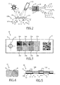
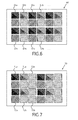
- Figs. 6 and 7 show different patterns of optical windows with first and second marker areas as well as reference areas.
- the first and second marker areas are divided into sub-areas.
- the patterns of the reference areas and the optical windows comprising the first and second marker areas can be chosen according to the needs of a specific measurement.
- Fig. 6 shows a marker 60 with a check board design for two wavelengths with alternating reference areas 61a and first marker areas 61b for a first wavelength and reference areas 62a and second marker areas 62b for a second wavelength.
- red is used as the first wavelength
- infrared is used as the second wavelength.
- Fig. 7 shows an alternative embodiment of a marker 70 wherein the distribution of the reference areas 71a, 72a and optical windows for the first and second marker areas 71b, 72b are optimized depending on the expected signal strength. For example, the signal at a first required wavelength, for example green, is stronger than signal at the second required wavelength, for example red. Thus, the overall second marker area 72b is increased with respect to the overall first marker area 71b to achieve a similar signal strength at both wavelengths.
- the present invention can be applied in the field of health care, e.g. unobtrusive remote patient monitoring, general surveillances, security monitoring and so-called lifestyle environments, such as fitness equipment, or the like.
- Applications may include monitoring of oxygen saturation (pulse oximetry), heart rate, blood pressure, cardiac output, changes of blood perfusion, assessment of autonomous functions, and detection of peripheral vascular diseases.
- a computer program may be stored/distributed on a suitable non-transitory medium, such as an optical storage medium or a solid-state medium supplied together with or as part of other hardware, but may also be distributed in other forms, such as via the Internet or other wired or wireless telecommunication systems.
- a suitable non-transitory medium such as an optical storage medium or a solid-state medium supplied together with or as part of other hardware, but may also be distributed in other forms, such as via the Internet or other wired or wireless telecommunication systems.
Abstract
The present invention relates to remote photoplethysmography and in particular to a system (1) and method for determining vital sign information of a subject (100). The system comprises a marker (10, 10', 30, 40, 50, 60, 70) for application to a skin (104) of the subject, said marker further comprising a first marker area (11, 11', 23, 34b, 41, 54b, 61b, 71b) configured to transmit light (A, B) at a first wavelength and a second marker area (12, 12', 24, 35b, 42, 55b, 62b, 72b) configured to transmit light (C, D) at a second wavelength, a detection unit (2, 22) for detecting radiation received from the first marker area and from the second marker area of the marker, and an analysis unit (6) for determining the vital sign information of the subject from the detected radiation from the first marker area and from the second marker area.
Description
- The present invention relates to a system and method for determining vital sign information of a subject. In particular, the present invention relates to optical measurement approaches which can be used for remotely determining vital signs of an observed subject. In this context, optical measurement may refer to photo-plethysmography (PPG) and, more specifically, to pulse oximetry.
- Vital signs of a person, for example the heart rate (HR), the respiration rate (RR) or the blood oxygen saturation, serve as indicators of the current state of a person and as powerful predictors of serious medical events. For this reason, vital signs are extensively monitored in inpatient and outpatient care settings, at home or in further health, leisure and fitness settings.
- One way of measuring vital signs is plethysmography. Plethysmography generally refers to the measurement of volume changes of an organ or a body part and in particular to the detection of volume changes due to a cardio-vascular pulse wave traveling through the body of a subject with every heart beat.
- Photoplethysmography (PPG) is an optical measurement technique that evaluates a time-variant change of light reflectance or transmission of an area or volume of interest. PPG is based on the principle that blood absorbs light more than surrounding tissue, so variations in blood volume with every heart beat affect transmission or reflectance correspondingly. Besides information about the heart rate, a PPG waveform can comprise information attributable to further physiological phenomena such as the respiration. By evaluating the transmissivity and/or reflectivity at different wavelengths (typically red and infrared), the blood oxygen saturation can be determined.
- Conventional pulse oximeters for measuring the heart rate and the oxygen saturation of a subject are attached to the skin of the subject, for instance to a finger tip, earlobe or forehead. Therefore, they are referred to as 'contact' PPG devices. A typical pulse oximeter comprises a red LED and an infrared LED as light sources and one photodiode for detecting light that has been transmitted through patient tissue. Commercially available pulse oximeters quickly switch between measurements at a red and an infrared wavelength and thereby measure the transmissivity of the same area or volume of tissue at two different wavelengths. This is referred to as time-division-multiplexing. The transmissivity over time at each wavelength gives the PPG waveforms for red and infrared wavelengths. Although contact PPG is regarded as a basically non-invasive technique, contact PPG measurement is often experienced as being unpleasant, since the pulse oximeter is directly attached to the subject and any cables limit the freedom to move.
- Recently, non-contact, remote PPG devices for unobtrusive measurements have been introduced. Remote PPG utilizes light sources or, in general radiation sources, disposed remotely from the subject of interest. Similarly, also a detector, e.g., a camera or a photo detector, can be disposed remotely from the subject of interest. Therefore, remote photoplethysmographic systems and devices are considered unobtrusive and well suited for medical as well as non-medical everyday applications.
- Wieringa, et al., "Contactless Multiple Wavelength Photoplethysmographic Imaging: A First Step Toward "SpO2 Camera" Technology," Ann. Biomed. Eng. 33, 1034-1041 (2005), discloses a remote PPG system for contactless imaging of arterial blood oxygen saturation in tissue based upon the measurement of plethysmographic signals at different wavelengths. The system comprises a monochrome CMOS-camera and a light source with LEDs of three different wavelengths. The camera sequentially acquires three movies of the subject. During each movie, the subject is illuminated by the light source at a different wavelength. The pulse rate can be determined from a movie at a single wavelength, whereas at least two movies at different wavelengths are required for determining the oxygen saturation. The measurements are performed in a darkroom, using only one wavelength at a time. The patient is not allowed to move between the subsequent measurements at different wavelengths. A further problem is that a measurement in darkness is not practical for unobtrusive medical and non-medical applications.
- It is an object of the present invention to provide an improved system and method for unobtrusively and economically determining vital sign information of a subject. It would be advantageous to provide a system and method for operation under ambient light conditions. Further advantageously the system and method enable parallel and possibly real-time measurement of the heart rate and oxygen saturation.
- In a first aspect of the present invention a system for determining vital sign information of a subject is presented that comprises
- a marker for application to a skin of the subject, said marker further comprising a first marker area configured to transmit light at a first wavelength and a second marker area configured to transmit light at a second wavelength,
- a detection unit for detecting radiation received from the first marker area and from the second marker area of the marker, and
- an analysis unit for determining the vital sign information of the subject from the detected radiation from the first marker area and from the second marker area.
- In a further aspect of the present invention a marker for use in the aforementioned system is presented that comprises a first marker area configured to transmit light at a first wavelength, a second marker area configured to transmit light at a second wavelength, and wherein the marker is adapted for application to the skin of the subject.
- In a further aspect of the present invention a device for use in the aforementioned system is presented that comprises a detection unit for detecting radiation received from a first marker area, configured to transmit light at a first wavelength, and from a second marker area, configured to transmit light at a second wavelength, of a marker applied to the skin of a subject, and an analysis unit for determining the vital sign information of the subject from the detected radiation from the first marker area and from the second marker area.
- In a further aspect of the present invention a method for determining vital sign information of a subject is presented that comprises the steps of
- detecting radiation received from a first marker area marker area, configured to transmit light at a first wavelength, and from a second marker area, configured to transmit light at a second wavelength, of a marker applied to a skin of the subject, and
- determining the vital sign information of the subject from the detected radiation from the first marker area and from the second marker area. In an embodiment, the method further comprises the step of applying the marker to the skin of the subject.
- In yet another aspect of the present invention, there is provided a computer program which comprises program code means for causing a computer to perform the steps of the proposed method when said computer program is carried out on a computer. Further, a non-transitory computer-readable storage medium that stores therein such a computer program product, which, when executed by a processor, causes said steps of the method disclosed herein to be performed, is presented.
- Preferred embodiments of the invention are defined in the dependent claims. It shall be understood that the claimed marker, device, method, computer program and medium have similar and/or identical preferred embodiments as the claimed system and as defined in the dependent claims.
- The term 'vital sign' as used in the context of the present invention refers to a physiological parameter of a subject and derivative parameters. In particular, the term 'vital sign' comprises heart rate (HR) (sometimes also called pulse rate), heart rate variability (pulse rate variability), pulsatility strength, perfusion, perfusion indicator, perfusion variability, Traube Hering Mayer waves, respiratory rate (RR), body temperature, blood pressure, a concentration of a substance in blood and/or tissue, such as an oxygen saturation or a glucose level.
- The term 'vital sign information' as used in the context of the present invention comprises the one or more measured vital signs as defined above. Furthermore, the term "vital sign information" comprises data referring to a physiological parameter, corresponding waveform traces or data referring to a physiological parameter over time that can serve for subsequent analysis.
- The present invention is based on the idea that, instead of sequentially measuring the same area or volume of tissue at different wavelengths, the vital sign information can be determined from spatially separated areas or volumes of tissue that are measured in parallel. In other words, the inventors have found that it is possible to determine vital sign information from a photoplethysmographic measurement at different wavelengths at different, spatially separated areas or volumes. This can be thought of as space-division-multiplexing. Advantages are that the measurement can be performed under ambient light conditions and that no sequential narrow-band illumination at different wavelengths is required as proposed in the prior art.
- According to an aspect of the present invention, a marker is proposed that comprises a first marker area configured to transmit light at a first wavelength and a second marker area configured to transmit light at a second wavelength. The first marker area and the second marker area thereby define the spatially separate areas for determining the vital sign information. Each marker area is configured to transmit light at a different wavelength, so that the concentration of a substance can be determined based on a comparison of the light at the two different wavelengths. The use of a marker has the advantage that no specific additional filtering at the detection unit is needed. A single detection unit can acquire all the required information which is beneficial for a low system cost.
- Optionally, the marker comprises further marker areas that are configured to transmit light at further wavelengths. The wavelengths of interest also comprise non-visible wavelengths of electromagnetic radiation, including infrared and ultra-violet wavelengths.
- As used herein, the term "wavelength" also refers to a band of wavelengths or wavelength portion. It is to be understood as a spectral range having a limited spectral width. For example, for an optical filter the term wavelength refers to a pass band of the filter. Hence, the term wavelength is not limited to one single wavelength but is also used for a wavelength range, for example of some nanometers or some tens of nanometers, around a center wavelength. Moreover the term wavelength in the context of a filter can also refer to multiple discontinuous spectral ranges of one and the same filter element.
- As used herein, the term "detection unit" refers to a device for detecting electromagnetic radiation. It is configured to detect radiation received from the first marker area and from the second marker area. In a preferred embodiment, the detection unit is a camera with an image sensor, such as a CCD or CMOS image sensor, that comprises an array of light sensitive pixels. The output of the detection unit is referred to as radiation data. For example, the radiation data is a series of images over time, thus a video stream. The camera can be a monochrome or color camera. An RGB image sensor for a color camera comprises a color filter array with filters for the red, green and blue color channel. When using an RGB color camera, the overall filter characteristic of the system includes both the transmission characteristic of the marker areas as well as the filter characteristic of the color channels of the camera. In an embodiment, the transmission wavelength of the first marker area lies within a first one of the RGB channels and the transmission wavelength of the second marker area lies within a second one of the RGB channels. By selecting the transmission characteristics of the marker areas accordingly, the spatial separation of the first and second marker area can be further supported by the frequency selective detection of the RGB camera. Thereby, the requirements for the transmission characteristic of the first and second marker area can be relaxed and the system cost is reduced.
- The radiation received from the first or second marker area typically comprises two components. Firstly, the received radiation comprises light reflected at the marker and/or at the skin surface, i.e. light that has not penetrated the tissue and does not carry information about light absorption in the tissue. Secondly, the received radiation comprises light that has penetrated into the skin and is reflected from inside the tissue. This second portion of the received radiation has a time-variant intensity due to the time-variant absorption and/or transmission of light within the tissue. The interaction of light with biological tissue is complex and includes the optical processes of (multiple) scattering, backscattering, absorption, transmission and (diffuse) reflection. The term "reflect" as used in this context is not to be construed as limited to specular reflection but comprises the aforementioned types of interaction of light with tissue and any combinations thereof.
- Optionally the system further comprises a light source for emission of light at said first wavelength and/or at said second wavelength in order to ensure that sufficient light at the respective wavelength is available. Further optionally, the system comprises a control unit to control the light power such that the detection unit can be operated in its optimum operating point, in particular such that for example noise or alternatively saturation effects do not disturb the measurement. In a preferred embodiment, however, the system only uses ambient light.
- The analysis unit is configured to determine the vital sign information of the subject from the detected radiation from the first marker area and from the second marker area. The analysis unit receives the radiation data from the detection unit. For determining the heart rate of the subject it is sufficient to evaluate the time-variant radiation received from a single marker area or even from bare skin outside a marker area. However, for determining the concentration of a substance, for example for determining the blood oxygen saturation or glucose level, the analysis of radiation at different wavelengths is required as described above. The analysis unit evaluates the time-variant signals from the two spatially separate marker areas and thereby evaluates two different wavelengths in parallel. For example, light received from the first marker area falls onto a first group of pixels of an image sensor that is part of the detection unit and light from the second marker area falls onto a second group of pixels of the image sensor. For a better signal-to-noise ratio, signals of pixels of a group can be combined.
- According to a preferred embodiment the system further comprises an image processing unit for identifying the first marker area and the second marker area in the detected radiation. The image processing unit is an optional element that is located between the detection unit and the analysis unit. The image processing unit receives radiation data, for example a video stream, from the detection unit. The image processing unit comprises image processing means for identifying the marker in the received radiation data. For example, the marker has particular features that can be identified in an image of the video stream. Analysis methods known from image processing and video analysis can be applied. Within the marker, the first marker area and the second marker area are localized. Hence, the image processing unit provides the analysis unit with processed radiation data that comprises information about the location of the first marker area and the second marker area in the radiation data. For example, the image processing unit identifies the pixel or group of pixels that represent portions of the image sensor that received radiation from the first marker area and pixels or group of pixels that received radiation from the second marker area respectively. The image processing unit can be incorporated into the analysis unit.
- In a further embodiment, the system according to the present invention further comprises a carrier element for carrying the marker. The carrier element features at least a first region to accommodate the first marker area and a second region to accommodate the second marker area. In general, the carrier element can be thought of as an element that provides mechanical support for the marker, for example, a type of patch, label or similar structure that can be attached to the skin of the subject. The carrier element can be made from a material of a group of materials comprising paper, textile, rubber or further materials used for patches, in particular for patches for medical applications.
- In another embodiment, the carrier element further comprises an adhesive for attaching the carrier element to the skin of the subject. Since in a preferred embodiment the carrier element is directly attached to the skin of the subject a biocompatible adhesive is used.
- In yet another embodiment, the first marker area and/or the second marker area comprise an optical filter plate that is attached to the carrier element. The optical filter plate ensures that only light of the desired wavelength or wavelength band is transmitted. The types of filter plate include absorption filters as well as dielectric filters. Advantageously, the carrier element comprises an opening and the optical filter plate is located in said opening. The opening is also referred to as a window or optical window.
- According to an alternative embodiment, the marker comprises a first dye applied to the skin of the subject in the first marker area and/or a second dye applied to the skin of the subject in the second marker area. Instead of using optical filter plates, this embodiment uses colored dyes, wherein the first dye transmits light at a first wavelength and the second dye transmits light at a second wavelength. While the optical filter plates are typically attached to the carrier element, the dyes can directly be applied to the skin of the subject without the need of a carrier element.
- In a further embodiment, the marker further comprises a reference area of predefined reflection characteristic. This reference area can be used for calibrating the detection unit since the reflection characteristic for a predetermined range of wavelengths is known. In particular when the system is equipped with an optional light source and control unit, the reference area in the detected radiation can serve for adjusting the sensitivity of the detection unit and/or for adjusting the power and/or spectrum of the light source. The marker can also comprise more than one reference area, wherein each reference area has a different reflection characteristic. For example, a red reference area is used to determine the optical power in the red spectral region, whereas a reference area that reflects light at the infrared is used to determine the optical power in the infrared spectral region. Based on these measurements, the sensitivity of the detection unit can be adjusted. Alternatively, the measurement time is adjusted to achieve a sufficiently good signal to noise ratio.
- According to a further aspect of this embodiment, the reference area is opaque. In other words, the reference area blocks any light passing through the marker but only reflects light that is incident on the reference area. This ensures that radiation received from the reference area is substantially free from disturbances in particular free from reflected or backscattered radiation from the underlying tissue. Thus, light from the first and/or second marker area provides plethysmographic information, whereas light from the reference area does not carry plethysmographic information and serves as a reference.
- Moreover the reference area can be used to determine any temporal or spectral disturbances of the ambient light or an artificial light source, for example slow changes during the day or systematic influences such as 50/60Hz flicker or a pulse-width modulation of a light source. The measured intensity from the first and/or second marker area can be compensated for such disturbances.
- In yet another embodiment, the marker further comprises a graphical pattern. The graphical pattern is adapted to be detectable in the radiation data by the analysis unit or by the optional image processing unit. Preferably, the graphical pattern has a high image contrast, for example a black and white pattern. Alternatively, the graphical pattern comprises different colors that can be clearly distinguished. Favorably, the graphical pattern is optimized to be machine-readable such as a bar code, a matrix bar code, alphanumerical characters, a QR-code or the like. For the image processing unit it is easier to detect a specified graphical pattern in the observed scene than analyzing unspecified image features. Optionally, the graphical pattern is a machine-readable code that stores information, such as a patient identifier for assigning the measured vital sign information to a patient or a body part of the patient. The encoded information can comprise configuration data for configuring the system for determining vital sign information, for example a required sensitivity or information about the vital sign information that is to be measured. The arrangement of the first marker area and the second marker area as well as the size and/or shape of a carrier element can also be seen as a graphical pattern.
- Optionally, markers can be fabricated or adjusted by printing different layers of ink or dye on a carrier element. The color and opacity of the ink can be adjusted such that the correct intensity and spectral components are transmitted or blocked. Alternatively or in addition, a graphical pattern can be printed as a part of the marker.
- In a further embodiment, the first marker area and/or the second marker area comprise sub-areas. In other words, a marker area can be composed of a plurality of smaller sections. For example, the sub-areas of the first marker area and/or the second marker area are arranged in a checkered pattern. This ensures that the first marker areas and second marker areas are not separated too far from one another but still the overall marker area covers a desired skin area.
- According to yet another aspect of the system according to the present invention, the marker further comprises a stimulant for increasing the blood perfusion in a tissue of the subject in contact with the marker. As explained above, photoplethysmography relies on the volume change of blood vessels in the tissue. Hence, for increasing the signal strength, it is desirable to ensure a sufficient blood flow in the vessels underneath the marker when the marker is applied to the subject whose vital signs are to be determined.
- These and other aspects of the invention will be apparent from and elucidated with reference to the embodiments described hereinafter. In the following drawings
-
Fig. 1 shows an exemplary embodiment of the system for determining vital sign information of a subject according to the present invention; -
Fig. 2 shows the determination of vital sign information with the system according to the present invention; -
Fig. 3 shows a first example of a marker; -
Fig. 4 shows a second example of a marker; -
Fig. 5 shows a third example of a marker; -
Fig. 6 shows an example of a marker with sub-areas; -
Fig. 7 shows an alternative example of a marker with sub-areas. -
Fig. 1 shows an exemplary embodiment of asystem 1 for determiningvital sign information 7 of a subject 100 according to the present invention. Thesystem 1 comprises amarker 10 for application to a skin of the subject 100, adetection unit 2 and ananalysis unit 6 as the basic components. In this example, the system for determining vital sign information of the subject is employed in a clinical setting, where the subject 100 lies inbed 103. - The
marker 10 further comprises afirst marker area 11 configured to transmit light at a first wavelength and asecond marker area 12 configured to transmit light at a second wavelength. Thedetection unit 2 is adapted to detect radiation received from thefirst marker area 11 and from thesecond marker area 12 of themarker 10. In this example, thedetection unit 2 is connected to an optionalimage processing unit 4. Thedetection unit 2 providesradiation data 3 that represents the detected radiation, to theimage processing unit 4 in form of a video stream. Theimage processing unit 4 identifies thefirst marker area 11 and thesecond marker area 12 in theradiation data 3. Theimage processing unit 4 in turn is connected to theanalysis unit 6. Theimage processing unit 4 provides preprocessed radiation data 5 to theanalysis unit 6. The preprocessed radiation data 5 in this example comprises information about which region of the images of the video stream of theradiation data 3 depict thefirst marker area 11 and thesecond marker area 12. Theanalysis unit 6 in turn determines thevital sign information 7 of the subject from time-variant intensity in thefirst marker area 11 and in thesecond marker area 12. In this example, the vital sign information comprises a heart rate and a blood oxygen saturation. - The
image processing unit 4 for identifying thefirst marker area 11 and the second marker area can also be incorporated into theanalysis unit 6. Alternatively, theradiation data 3 is directly provided to theanalysis unit 6. In this case, thefirst marker area 11 and thesecond marker area 12 can be either determined by manually selecting the marker areas in the images of the video stream. Alternatively, the subject 100 with themarker 10 has to be located in a predetermined position within the field of view of thedetection unit 2 such that thefirst marker area 11 and thesecond marker area 12 are located at a predetermined position. However, an automated identification of themarker 10 in theradiation data 3 by theimage processing unit 4 is preferred. - In the shown example, the
marker 10 is directly applied to the bare skin of theforehead 101 of thesubj ect 100. An alternative marker 10' with first marker area 11' and second marker area 12' is located at theleft forearm 102 of the subject 100. The size and shape of themarker 10, 10' can be adapted depending on the anatomic location. - The scenery is illuminated by a source of radiation, such as
sunlight 7a or an artificiallight source 7b. Theradiation source radiation 8a, 8b towards the subject 100. In addition, or in the alternative, thesystem 1 can also comprise an optional systemlight source 7c that emits light 8c towards the subject 100. The use of a systemlight source 7c is particularly beneficial if theambient light sources ambient light sources - An
optional control unit 9 is adapted to control the sensitivity of thedetection unit 2 and/or to control the power of the systemlight source 7c. Because the dynamic range of a detector or image sensor that is used as thedetection unit 2 is limited, shutters and electronic offsets may have to be adjusted according to the lighting situation in the observed scene. The systemlight source 7c can be part of a control loop which sets an optimal operating point of the image sensor of thedetection unit 2. Optimal in this context refers to an output signal without signal clipping, no saturation of individual detectors of the image sensors and a good signal-to-noise ratio at least for the detector area corresponding to first and/or second marker area. -
Fig. 2 illustrates the determination of vital sign information of a subject with thesystem 1 according to the present invention.Fig. 2 shows alight source 21, adetection unit 22 and a marker having afirst marker area 23 and asecond marker area 24. The marker is applied to askin tissue 104 of a subject. The tissue comprisesblood vessels 105. - In this embodiment, the
light source 21 emits light at at least a first wavelength (indicated with dotted lines) and a second wavelength (indicated with dashed lines). Thefirst marker area 23 is configured to transmit light at a first wavelength, wherein said first wavelength corresponds to the first wavelength of thelight source 21. Thesecond marker area 24 is configured to transmit light at a second wavelength, wherein said second wavelength corresponds to the second wavelength of thelight source 21.Fig. 2 sketches two light rays A, B at the first wavelength and two light rays C, D at the second wavelength. Since thefirst marker area 23 is configured to transmit light at the first wavelength, the ray A passes through the marker and penetrates into theskin 104 of the subject 100. Some of the light is absorbed within theskin 104, while some of the light is reflected or scattered in the tissue and reaches thedetection unit 22. The absorption and/or reflection characteristic is time-variant and represents the time-variant perfusion of thetissue 104 with itsblood vessels 105. - The
detection unit 22 comprises receiving optics, for example a receiver lens, and anarray 25 of photo detectors or pixels that form an image sensor. Light that is received from the first marker area is imaged onto a first group or array ofpixels 26. Correspondingly, light received from thesecond marker area 24 is imaged onto a second group ofpixels 27. - Since the absorption of light in the
tissue 104 is time-variant, the light intensity incident on the image sensor of thedetection unit 22 is also time-variant. The time-variant intensity on the area ofpixels 26 is depicted bycurve 28. The time-variant intensity incident on the group ofpixels 27 is depicted bycurve 29. - Since the first marker area is configured to transmit light at the first wavelength only, light at the second wavelength does not pass the marker area and penetrate into the tissue as indicated by light ray C. Nonetheless, some of the light can be scattered back at the marker surface and reach the
detection unit 22. This light is not modulated by the pulsatile variation of the blood volume and gives an offset. The intensity modulation depicted bycurve 28 is thus due to the time-variant reflection in thetissue 104 at the first wavelength. - Correspondingly, a ray of light D at the second wavelength can pass through the
second marker area 24 whereas a ray of light B at the first wavelength is blocked. The intensity modulation depicted bycurve 29 is thus due to the time-variant reflection in thetissue 104 at the second wavelength. - The pulse rate of the subject can be directly determined from the time-variant intensity in one of the
curves - Contact pulse oximeters typically transmit red (R) and infrared (IR) (or, more precisely, in some cases near infrared) light through a vascular tissue of the subject of interest. The respective light portions (R/IR) can be transmitted and detected in an alternating (fast-switching) manner. Given that the respective spectral portions are differently absorbed by oxygenated hemoglobin (HbO2) and reduced hemoglobin (Hb), blood oxygen saturation eventually can be processed. An oxygen saturation (SO2) estimation algorithm can make use of a ratio of the signals related to the red and the infrared portion. Furthermore, the algorithm can consider a non-pulsatile signal component. Typically, the PPG signal comprises a DC component and a relatively small pulsatile AC component. Furthermore, SO2 estimation generally involves an empirically derived calibration factor applied to the processed values. Typically, the calibration factor (or, calibration curve) is determined upon reference measurements involving invasive blood oxygen saturation measurements. A calibration factor is required since a PPG device basically detects a ratio of (spectral) signal portions which has to be transferred into a blood oxygen saturation value which typically involves a ratio of HbO2 and Hb. For instance, but not intended to limit the present disclosure, blood oxygen saturation estimation can be based on the following general equation:

whereas PPG devices merely mediately detect HbO2 and Hb from the spectral response at at least two wavelengths. - Generally, the measured
intensity curve 
where C is a calibration parameter. C may stand for a large variety of calibration parameters applicable to the AC/DC relationship and should therefore not be interpreted in the strict algebraic sense of equation (2). C may, for example, represent a fixed constant value, a set of fixed constants or an adjustable calibration parameter. By way of example, another exemplary SaO2 derivation model can be expressed as:
where C1 and C2 can be considered calibration parameters of a linear approximation. In an exemplary embodiment, the signal calibration parameter determination can be directed to adjust or adapt the parameter C1. Still, in the alternative, SaO2 derivation may also be based on value tables deposited in (or accessible by) thedevice 1. The value tables (or: data bases) may provide for a discrete representation of the relationship between detected PPG signals und the desired calibration parameter. Also in that case an adaptable calibration parameter may be applied to improve the accuracy of the vital parameter determination. - It should be understood that the equations (2) and (3) are primarily presented for illustrative purposes. They should not be construed as limiting the scope of the present disclosure. In practice, the skilled person may determine and establish further appropriate SaO2 derivation models. Alternative wavelength combinations, for example green and red, can be used depending on the substance to be detected. While the measurement of SaO2 has been described in detail, this is to be understood as an example for the general concept of measuring the concentration of a substance in blood and/or tissue.
-
Fig. 3 shows a more detailed embodiment of a marker for use in asystem 1 for determining vital sign information of a subject according to the present invention. Themarker 30 features a firstgraphical pattern 32, a secondgraphical pattern 33,reference areas marker areas transparent marker area 37b. - The
carrier element 31 carries themarker 30 with its elements and provides mechanical stability. In this embodiment, thecarrier element 31 is a patch or band-aid that can be directly attached to the skin of the subject 100 with an adhesive. The carrier element is made from an opaque rubber-like material that does not transmit light. Therefore, the carrier element features openings or windows at the positions of themarker areas - In each of the
windows filter plate 34b is configured to transmit light at a first wavelength, thefilter plate 35b is configured to transmit light at a second wavelength, thefilter plate 36b is configured to transmit light at a third wavelength.Marker area 37b does not have a frequency-selective filter but is transparent so that the skin underneath thearea 37b can be seen by the detection unit as an unfiltered reference of the skin. - The
reference areas marker area 34b is configured to transmit red light and thereference area 34a has a red color so that it can serve as a reference in particular as to how much red light is available in the radiation that is incident on the marker. - The
graphical pattern 32 serves as an alignment indicator. The geometrical structure enables theimage processing unit 4 to determine the position and/or orientation of themarker 30. Themarker 30 furthermore features a machine-readablegraphical pattern 33 in form of a QR-code. This code comprises information about the subject such that the determined vital sign information can be assigned to the subject, for example to an electronic health record (EHR). The code can also comprise information about the site where the marker is attached to the subject's body, so that different measurements can be taken from the same subject at the same time that are specific for the measurement location (e.g. forehead and arm). - Even though
Fig. 3 shows a plurality of features, not all of them are mandatory.Fig. 4 shows the most basic configuration having two marker areas. In this example, the marker comprises a first dye directly applied to the skin of the subject in the first marker area and a second dye directly applied to the skin of the subject in a second marker area. The dye can be, for example, rubber stamped, drawn, sprayed or printed on the skin. The dye of the first marker area is configured to transmit light at a first wavelength, whereas the dye at the second marker area is configured to transmit light at the second wavelength. An additional reference area can be applied accordingly. -
Fig. 5 shows a side view of a marker similar to the one presented inFig. 3 . It is attached to theskin 104 of a subj ect. Acarrier element 51 provides mechanical stability to themarker 50. On the side of thecarrier element 51 facing theskin 104 of the subject, thecarrier element 51 comprises an adhesive 52 for attaching the carrier element to theskin 104 of the subject. The adhesive 52 further comprises a stimulant for increasing the blood perfusion in thetissue 104 of the subject that is in contact with thecarrier element 51 with themarker 50. - On the opposite side of the
carrier element 51, themarker 50 featuresreference areas first marker area 54b configured to transmit light at a first wavelength and asecond marker area 55b configured to transmit light at a second wavelength. This is achieved by optical filter plates 56, 57 that are placed in position of the first and second marker area and laminated into thecarrier element 51. Optionally, the adhesive is not applied in themarker areas -
Figs. 6 and 7 show different patterns of optical windows with first and second marker areas as well as reference areas. In this example, the first and second marker areas are divided into sub-areas. The patterns of the reference areas and the optical windows comprising the first and second marker areas can be chosen according to the needs of a specific measurement. - For some measurements, it is important to get the signals for each wavelength from closely spaced areas of the tissue. In this case it is advantageous to have several smaller optical windows, for example in a check board design.
Fig. 6 shows amarker 60 with a check board design for two wavelengths with alternatingreference areas 61a andfirst marker areas 61b for a first wavelength andreference areas 62a andsecond marker areas 62b for a second wavelength. For example, for blood oxygen saturation measurement red is used as the first wavelength and infrared is used as the second wavelength. -
Fig. 7 shows an alternative embodiment of amarker 70 wherein the distribution of thereference areas second marker areas second marker area 72b is increased with respect to the overallfirst marker area 71b to achieve a similar signal strength at both wavelengths. - By way of example, the present invention can be applied in the field of health care, e.g. unobtrusive remote patient monitoring, general surveillances, security monitoring and so-called lifestyle environments, such as fitness equipment, or the like. Applications may include monitoring of oxygen saturation (pulse oximetry), heart rate, blood pressure, cardiac output, changes of blood perfusion, assessment of autonomous functions, and detection of peripheral vascular diseases.
- While the invention has been illustrated and described in detail in the drawings and foregoing description, such illustration and description are to be considered illustrative or exemplary and not restrictive; the invention is not limited to the disclosed embodiments. Other variations to the disclosed embodiments can be understood and effected by those skilled in the art in practicing the claimed invention, from a study of the drawings, the disclosure, and the appended claims.
- In the claims, the word "comprising" does not exclude other elements or steps, and the indefinite article "a" or "an" does not exclude a plurality. A single element or other unit may fulfill the functions of several items recited in the claims. The mere fact that certain measures are recited in mutually different dependent claims does not indicate that a combination of these measures cannot be used to advantage.
- A computer program may be stored/distributed on a suitable non-transitory medium, such as an optical storage medium or a solid-state medium supplied together with or as part of other hardware, but may also be distributed in other forms, such as via the Internet or other wired or wireless telecommunication systems.
- Any reference signs in the claims should not be construed as limiting the scope.
Claims (16)
- A system (1) for determining vital sign information (7) of a subject (100) comprising- a marker (10, 10', 30, 40, 50, 60, 70) for application to a skin (104) of the subject, said marker further comprising a first marker area (11, 11', 23, 34b, 41, 54b, 61b, 71b) configured to transmit light (A, B) at a first wavelength and a second marker area (12, 12', 24, 35b, 42, 55b, 62b, 72b) configured to transmit light (C, D) at a second wavelength,- a detection unit (2, 22) for detecting radiation received from the first marker area and from the second marker area of the marker, and- an analysis unit (6) for determining the vital sign information of the subject from the detected radiation from the first marker area and from the second marker area.
- The system according to claim 1,
further comprising an image processing unit (4) for identifying the first marker area (11, 11', 23, 34b, 41, 54b, 61b, 71b) and the second marker area (12, 12', 24, 35b, 42, 55b, 62b, 72b) in the detected radiation. - The system according to claim 1,
further comprising a carrier element (31, 51) for carrying the marker. - The system according to claim 3,
wherein the carrier element (31, 51) further comprises an adhesive (52) for attaching the carrier element to the skin (104) of the subject (100). - The system according to claim 3,
wherein the first marker area (11, 11', 23, 34b, 41, 54b, 61b, 71b) and/or the second marker area (12, 12', 24, 35b, 42, 55b, 62b, 72b) comprise an optical filter plate (56, 57) that is attached to the carrier element (31, 51). - The system according to claim 1,
wherein the marker (40) comprises a first dye applied to the skin of the subject in the first marker area (41) and/or a second dye applied to the skin of the subject in the second marker area (42). - The system according to claim 1,
wherein the marker (30, 40, 60, 70) further comprises a reference area (34a, 35a, 36a, 54a, 55a, 61a, 62a, 71a, 72a) of predefined reflection characteristic. - The system according to claim 7,
wherein the reference area is opaque. - The system according to claim 1,
wherein the marker further comprises a graphical pattern (32, 33). - The system according to claim 1,
wherein the first marker area (61b, 71b) and/or the second marker area (62b, 72b) comprise sub-areas. - The system according to claim 1,
wherein the marker further comprises a stimulant (52) for increasing the blood perfusion in a tissue (104) of the subject (100) in contact with the marker (50). - A marker (10, 10', 30, 40, 50, 60, 70) for use in a system (1) according to claim 1 comprising- a first marker area (11, 11', 23, 34b, 41, 54b, 61b, 71b) configured to transmit light (A, B) at a first wavelength,- a second marker area (12, 12', 24, 35b, 42, 55b, 62b, 72b) configured to transmit light (C, D) at a second wavelength, and
wherein the marker is adapted for application to the skin (104) of the subject (100). - A device for use in a system (1) according to claim 1 comprising- a detection unit (2, 22) for detecting radiation received from a first marker area (11, 11', 23, 34b, 41, 54b, 61b, 71b), configured to transmit light (A, B) at a first wavelength, and from a second marker area (12, 12', 24, 35b, 42, 55b, 62b, 72b), configured to transmit light (C, D) at a second wavelength, of a marker (10, 10', 30, 40, 50, 60, 70) applied to the skin (104) of the subject (100), and- an analysis unit (6) for determining the vital sign information (7) of the subject from the detected radiation from the first marker area and from the second marker area.
- A method for determining vital sign information (7) of a subject (100) comprising the steps of- detecting radiation received from a first marker area marker area (11, 11', 23, 34b, 41, 54b, 61 b, 71 b), configured to transmit light (A, B) at a first wavelength, and from a second marker area (12, 12', 24, 35b, 42, 55b, 62b, 72b), configured to transmit light (C, D) at a second wavelength, of a marker (10, 10', 30, 40, 50, 60, 70) applied to a skin (104) of the subject, and- determining the vital sign information of the subject from the detected radiation from the first marker area and from the second marker area.
- The method according to claim 14 further comprising the step of- applying the marker (10, 10', 30, 40, 50, 60, 70) to the skin (104) of the subject (100).
- Computer program comprising program code means for causing a computer to carry out the steps of the method as claimed in claim 14 when said computer program is carried out on the computer.
Priority Applications (16)
| Application Number | Priority Date | Filing Date | Title |
|---|---|---|---|
| EP13154017.1A EP2762066A1 (en) | 2013-02-05 | 2013-02-05 | System and method for determining vital sign information of a subject |
| US14/165,642 US10660524B2 (en) | 2013-02-05 | 2014-01-28 | System and method for determining vital sign information of a subject |
| JP2015555747A JP6388604B2 (en) | 2013-02-05 | 2014-02-04 | System and method for determining vital sign information of a subject |
| EP14704928.2A EP2953530A1 (en) | 2013-02-05 | 2014-02-04 | System and method for determining vital sign information of a subject |
| PCT/IB2014/058781 WO2014122577A1 (en) | 2013-02-05 | 2014-02-04 | System and method for determining vital sign information of a subject |
| BR112015018351A BR112015018351A2 (en) | 2013-02-05 | 2014-02-04 | system for determining an individual's vital sign information, marker for use in a system, device for use in a system, method for determining an individual's vital sign information, and, computer program |
| CN201480007187.6A CN104968259B (en) | 2013-02-05 | 2014-02-04 | System and method for the vital sign information for determining object |
| CN201480007177.2A CN104981200B (en) | 2013-02-05 | 2014-02-04 | System and method for the vital sign information for determining object |
| RU2015137775A RU2688445C2 (en) | 2013-02-05 | 2014-02-04 | System and method for determining information on basic physiological indicators of a subject |
| EP14702292.5A EP2953529A1 (en) | 2013-02-05 | 2014-02-04 | System and method for determining vital sign information of a subject |
| JP2015555844A JP6525890B2 (en) | 2013-02-05 | 2014-02-04 | System and method for determining vital sign information of a subject |
| MX2015009946A MX2015009946A (en) | 2013-02-05 | 2014-02-04 | System and method for determining vital sign information of a subject. |
| US14/764,588 US9980650B2 (en) | 2013-02-05 | 2014-02-04 | System and method for determining vital sign information of a subject |
| CA2899988A CA2899988A1 (en) | 2013-02-05 | 2014-02-04 | System and method for determining vital sign information of a subject |
| PCT/EP2014/052143 WO2014122126A1 (en) | 2013-02-05 | 2014-02-04 | System and method for determining vital sign information of a subject |
| ZA2015/06510A ZA201506510B (en) | 2013-02-05 | 2015-09-04 | System and method for determining vital sign information of a subject |
Applications Claiming Priority (1)
| Application Number | Priority Date | Filing Date | Title |
|---|---|---|---|
| EP13154017.1A EP2762066A1 (en) | 2013-02-05 | 2013-02-05 | System and method for determining vital sign information of a subject |
Publications (1)
| Publication Number | Publication Date |
|---|---|
| EP2762066A1 true EP2762066A1 (en) | 2014-08-06 |
Family
ID=47630213
Family Applications (3)
| Application Number | Title | Priority Date | Filing Date |
|---|---|---|---|
| EP13154017.1A Withdrawn EP2762066A1 (en) | 2013-02-05 | 2013-02-05 | System and method for determining vital sign information of a subject |
| EP14702292.5A Withdrawn EP2953529A1 (en) | 2013-02-05 | 2014-02-04 | System and method for determining vital sign information of a subject |
| EP14704928.2A Withdrawn EP2953530A1 (en) | 2013-02-05 | 2014-02-04 | System and method for determining vital sign information of a subject |
Family Applications After (2)
| Application Number | Title | Priority Date | Filing Date |
|---|---|---|---|
| EP14702292.5A Withdrawn EP2953529A1 (en) | 2013-02-05 | 2014-02-04 | System and method for determining vital sign information of a subject |
| EP14704928.2A Withdrawn EP2953530A1 (en) | 2013-02-05 | 2014-02-04 | System and method for determining vital sign information of a subject |
Country Status (10)
| Country | Link |
|---|---|
| US (2) | US10660524B2 (en) |
| EP (3) | EP2762066A1 (en) |
| JP (2) | JP6388604B2 (en) |
| CN (2) | CN104968259B (en) |
| BR (1) | BR112015018351A2 (en) |
| CA (1) | CA2899988A1 (en) |
| MX (1) | MX2015009946A (en) |
| RU (1) | RU2688445C2 (en) |
| WO (2) | WO2014122126A1 (en) |
| ZA (1) | ZA201506510B (en) |
Cited By (5)
| Publication number | Priority date | Publication date | Assignee | Title |
|---|---|---|---|---|
| WO2017139895A1 (en) * | 2016-02-17 | 2017-08-24 | Nuralogix Corporation | System and method for detecting physiological state |
| WO2018047040A1 (en) * | 2016-09-08 | 2018-03-15 | Presens Precision Sensing Gmbh | Method for calibrated optical measurement and system therefor |
| CN108852307A (en) * | 2018-05-24 | 2018-11-23 | 重庆理工大学 | A kind of non-contact noninvasive Arteriosclerosis detecting device |
| US10242278B2 (en) | 2014-12-01 | 2019-03-26 | Koninklijke Philips N.V. | Device and method for skin detection |
| US11471083B2 (en) | 2017-10-24 | 2022-10-18 | Nuralogix Corporation | System and method for camera-based stress determination |
Families Citing this family (24)
| Publication number | Priority date | Publication date | Assignee | Title |
|---|---|---|---|---|
| CN104363831B (en) | 2012-06-12 | 2018-01-19 | 皇家飞利浦有限公司 | System for the life sign measurement based on camera |
| WO2015062969A1 (en) | 2013-11-01 | 2015-05-07 | Koninklijke Philips N.V. | System and method for determining vital sign information of a subject |
| CN105266759A (en) * | 2014-05-26 | 2016-01-27 | 义明科技股份有限公司 | Physiological signal detection device |
| WO2016057633A1 (en) | 2014-10-08 | 2016-04-14 | Revealix, Inc. | Automated systems and methods for skin assessment and early detection of a latent pathogenic bio-signal anomaly |
| WO2016111696A1 (en) * | 2015-01-09 | 2016-07-14 | Lifeq Global Limited | A ppg-based physiological sensing system with a spatio-temporal sampling approach towards identifying and removing motion artifacts from optical signals |
| CN106236060B (en) * | 2015-06-04 | 2021-04-09 | 松下知识产权经营株式会社 | Biological information detection device |
| US11103139B2 (en) | 2015-06-14 | 2021-08-31 | Facense Ltd. | Detecting fever from video images and a baseline |
| US11154203B2 (en) | 2015-06-14 | 2021-10-26 | Facense Ltd. | Detecting fever from images and temperatures |
| EP3393346B1 (en) * | 2015-12-21 | 2019-06-26 | Koninklijke Philips N.V. | Device, method and computer program product for continuous monitoring of vital signs |
| EP3422930A4 (en) * | 2016-03-03 | 2019-10-16 | Board Of Trustees Of Michigan State University | Method and apparatus for cuff-less blood pressure measurement |
| US10398324B2 (en) | 2016-03-03 | 2019-09-03 | Board Of Trustees Of Michigan State University | Method and apparatus for cuff-less blood pressure measurement in a mobile device |
| JP2017176267A (en) * | 2016-03-28 | 2017-10-05 | 富士ゼロックス株式会社 | Biological information measurement device and light-emitting device |
| US10335045B2 (en) | 2016-06-24 | 2019-07-02 | Universita Degli Studi Di Trento | Self-adaptive matrix completion for heart rate estimation from face videos under realistic conditions |
| CN109561843B (en) * | 2016-08-09 | 2022-07-15 | 皇家飞利浦有限公司 | Apparatus, system and method for monitoring peripheral arterial perfusion of a subject |
| CN116269261A (en) * | 2016-12-01 | 2023-06-23 | 松下知识产权经营株式会社 | Biological information processing method and biological information processing system |
| CA3076478C (en) * | 2017-09-21 | 2021-11-16 | Vital Biosciences, Inc. | Imaging biological tissue or other subjects |
| JP7268010B2 (en) * | 2017-09-22 | 2023-05-02 | インテュイティブ サージカル オペレーションズ, インコーポレイテッド | Increased visual differences between different tissues in computer-assisted teleoperated surgery |
| US10646145B2 (en) * | 2018-02-09 | 2020-05-12 | General Electric Company | Reflective SpO2 measurement system and method |
| EP3823525A4 (en) | 2018-07-16 | 2022-04-20 | BBI Medical Innovations, LLC | Perfusion and oxygenation measurement |
| EP3613337A1 (en) * | 2018-08-22 | 2020-02-26 | Nokia Technologies Oy | An apparatus, method and computer program for determining a biometric parameter |
| US11681886B2 (en) * | 2018-09-06 | 2023-06-20 | John P. Peeters | Genomic and environmental blockchain sensors |
| US11779222B2 (en) * | 2019-07-10 | 2023-10-10 | Compal Electronics, Inc. | Method of and imaging system for clinical sign detection |
| CN112617746B (en) * | 2019-10-09 | 2024-04-09 | 钜怡智慧股份有限公司 | Non-contact physiological signal detection device |
| TWI772689B (en) * | 2019-10-09 | 2022-08-01 | 鉅怡智慧股份有限公司 | Non-contact physiological signal measuring device |
Citations (4)
| Publication number | Priority date | Publication date | Assignee | Title |
|---|---|---|---|---|
| US20050106713A1 (en) * | 2003-09-03 | 2005-05-19 | Phan Brigitte C. | Personal diagnostic devices and related methods |
| US20100112680A1 (en) * | 2006-07-11 | 2010-05-06 | Paul Nigel Brockwell | Indicator system for determining analyte concentration |
| WO2011112559A2 (en) * | 2010-03-08 | 2011-09-15 | Bruce Adams | System, method and article for normalization and enhancement of tissue images |
| WO2012143842A2 (en) * | 2011-04-21 | 2012-10-26 | Koninklijke Philips Electronics N.V. | Device and method for vital sign measurement of a person |
Family Cites Families (41)
| Publication number | Priority date | Publication date | Assignee | Title |
|---|---|---|---|---|
| US5441048A (en) * | 1988-09-08 | 1995-08-15 | Sudor Partners | Method and apparatus for determination of chemical species in perspiration |
| GB9011887D0 (en) * | 1990-05-26 | 1990-07-18 | Le Fit Ltd | Pulse responsive device |
| US5267563A (en) * | 1991-06-28 | 1993-12-07 | Nellcor Incorporated | Oximeter sensor with perfusion enhancing |
| US5544649A (en) | 1992-03-25 | 1996-08-13 | Cardiomedix, Inc. | Ambulatory patient health monitoring techniques utilizing interactive visual communication |
| JPH06285048A (en) | 1993-03-19 | 1994-10-11 | Nellcor Inc | Oxygen analyzer with perfusion enhancing means |
| JP3547968B2 (en) * | 1998-01-19 | 2004-07-28 | 株式会社日本自動車部品総合研究所 | Pulse waveform detector |
| US6352517B1 (en) | 1998-06-02 | 2002-03-05 | Stephen Thomas Flock | Optical monitor of anatomical movement and uses thereof |
| US6980679B2 (en) * | 1998-10-23 | 2005-12-27 | Varian Medical System Technologies, Inc. | Method and system for monitoring breathing activity of a subject |
| US20050027182A1 (en) | 2001-12-27 | 2005-02-03 | Uzair Siddiqui | System for monitoring physiological characteristics |
| JP2004187980A (en) | 2002-12-12 | 2004-07-08 | Fuji Photo Film Co Ltd | Medical image processor and medical image processing method |
| CN101366632A (en) * | 2004-08-03 | 2009-02-18 | 武汉一海数字工程有限公司 | Mammary tissue blood oxygen function imaging system |
| DE102005036410A1 (en) | 2005-07-29 | 2007-02-01 | Biocam Gmbh | Method for determining the oxygen partial pressure distribution in at least one tissue surface section, in particular skin tissue surface section |
| US7499739B2 (en) * | 2005-10-27 | 2009-03-03 | Smiths Medical Pm, Inc. | Single use pulse oximeter |
| US20070142715A1 (en) * | 2005-12-20 | 2007-06-21 | Triage Wireless, Inc. | Chest strap for measuring vital signs |
| US20100056887A1 (en) * | 2006-11-27 | 2010-03-04 | Pioneer Corporation | Emission sensor device and bioinformation detecting method |
| US7434724B2 (en) * | 2006-12-22 | 2008-10-14 | Welch Allyn, Inc. | Dynamic barcode for displaying medical data |
| JP2008167853A (en) | 2007-01-10 | 2008-07-24 | Fujifilm Corp | Test sheet, object diagnostic apparatus and method, and program |
| JP5061353B2 (en) | 2007-06-19 | 2012-10-31 | 富士フイルム株式会社 | Inspection sheet |
| US20080317628A1 (en) * | 2007-06-19 | 2008-12-25 | Fujifilm Corporation | Check sheet |
| US8106344B2 (en) | 2008-02-18 | 2012-01-31 | Panasonic Corporation | Compound eye camera module |
| US20090226071A1 (en) * | 2008-03-06 | 2009-09-10 | Motorola, Inc. | Method and Apparatus to Facilitate Using Visible Light Images to Determine a Heart Rate |
| US8384916B2 (en) * | 2008-07-24 | 2013-02-26 | Massachusetts Institute Of Technology | Dynamic three-dimensional imaging of ear canals |
| US10729357B2 (en) | 2010-04-22 | 2020-08-04 | Leaf Healthcare, Inc. | Systems and methods for generating and/or adjusting a repositioning schedule for a person |
| US20100268094A1 (en) * | 2009-04-15 | 2010-10-21 | Oceanit Laboratories Inc. | Consumer electronic camera photoplethysmograph |
| RU2557887C2 (en) | 2009-07-15 | 2015-07-27 | Конинклейке Филипс Электроникс Н.В. | Method for automatic adjustment of time-varying parameter warning |
| US8670812B2 (en) * | 2009-07-23 | 2014-03-11 | Covidien Lp | Physiological sensor having a waist |
| FR2949658B1 (en) * | 2009-09-07 | 2012-07-27 | Salim Mimouni | OPTICAL PLETHYSMOGRAPHIC SIGNAL CAPTURE DEVICE USING MATRIX IMAGER |
| EP2486539B1 (en) * | 2009-10-06 | 2016-09-07 | Koninklijke Philips N.V. | Method and system for obtaining a first signal for analysis to characterize at least one periodic component thereof |
| CN102647941B (en) * | 2009-10-06 | 2015-11-25 | 皇家飞利浦电子股份有限公司 | For performing the method and system of long-range photoplethaysmography |
| JP2011147469A (en) * | 2010-01-19 | 2011-08-04 | Rohm Co Ltd | Biological information acquisition device |
| JP5446915B2 (en) * | 2010-01-21 | 2014-03-19 | セイコーエプソン株式会社 | Biological information detector and biological information measuring device |
| US8602988B2 (en) * | 2010-02-02 | 2013-12-10 | Recovery Science and Technology, LLC | Recovery determination methods and recovery determination apparatuses |
| US8761853B2 (en) | 2011-01-20 | 2014-06-24 | Nitto Denko Corporation | Devices and methods for non-invasive optical physiological measurements |
| US9713428B2 (en) * | 2011-01-21 | 2017-07-25 | Worcester Polytechnic Institute | Physiological parameter monitoring with a mobile communication device |
| US8718748B2 (en) | 2011-03-29 | 2014-05-06 | Kaliber Imaging Inc. | System and methods for monitoring and assessing mobility |
| DE102011017064A1 (en) * | 2011-04-14 | 2012-10-18 | Ingo Flore | Diagnostic measuring device with integrated spectrometer |
| CN103764019B (en) | 2011-09-02 | 2017-03-22 | 皇家飞利浦有限公司 | Camera for generating a biometrical signal of a living being |
| US20130267854A1 (en) * | 2012-04-09 | 2013-10-10 | Jami Johnson | Optical Monitoring and Computing Devices and Methods of Use |
| US20130303921A1 (en) * | 2012-05-11 | 2013-11-14 | Hong Kong Applied Science and Technology Research Institute Company Limited | System and Method for Measurement of Physiological Data with Light Modulation |
| CN104363831B (en) * | 2012-06-12 | 2018-01-19 | 皇家飞利浦有限公司 | System for the life sign measurement based on camera |
| JP6285048B2 (en) | 2014-11-28 | 2018-02-28 | 堺ディスプレイプロダクト株式会社 | Backlight device and liquid crystal display device |
-
2013
- 2013-02-05 EP EP13154017.1A patent/EP2762066A1/en not_active Withdrawn
-
2014
- 2014-01-28 US US14/165,642 patent/US10660524B2/en active Active
- 2014-02-04 CN CN201480007187.6A patent/CN104968259B/en not_active Expired - Fee Related
- 2014-02-04 CN CN201480007177.2A patent/CN104981200B/en not_active Expired - Fee Related
- 2014-02-04 WO PCT/EP2014/052143 patent/WO2014122126A1/en active Application Filing
- 2014-02-04 EP EP14702292.5A patent/EP2953529A1/en not_active Withdrawn
- 2014-02-04 JP JP2015555747A patent/JP6388604B2/en not_active Expired - Fee Related
- 2014-02-04 BR BR112015018351A patent/BR112015018351A2/en not_active IP Right Cessation
- 2014-02-04 WO PCT/IB2014/058781 patent/WO2014122577A1/en active Application Filing
- 2014-02-04 EP EP14704928.2A patent/EP2953530A1/en not_active Withdrawn
- 2014-02-04 US US14/764,588 patent/US9980650B2/en not_active Expired - Fee Related
- 2014-02-04 JP JP2015555844A patent/JP6525890B2/en not_active Expired - Fee Related
- 2014-02-04 MX MX2015009946A patent/MX2015009946A/en unknown
- 2014-02-04 CA CA2899988A patent/CA2899988A1/en not_active Abandoned
- 2014-02-04 RU RU2015137775A patent/RU2688445C2/en not_active IP Right Cessation
-
2015
- 2015-09-04 ZA ZA2015/06510A patent/ZA201506510B/en unknown
Patent Citations (4)
| Publication number | Priority date | Publication date | Assignee | Title |
|---|---|---|---|---|
| US20050106713A1 (en) * | 2003-09-03 | 2005-05-19 | Phan Brigitte C. | Personal diagnostic devices and related methods |
| US20100112680A1 (en) * | 2006-07-11 | 2010-05-06 | Paul Nigel Brockwell | Indicator system for determining analyte concentration |
| WO2011112559A2 (en) * | 2010-03-08 | 2011-09-15 | Bruce Adams | System, method and article for normalization and enhancement of tissue images |
| WO2012143842A2 (en) * | 2011-04-21 | 2012-10-26 | Koninklijke Philips Electronics N.V. | Device and method for vital sign measurement of a person |
Non-Patent Citations (2)
| Title |
|---|
| WIERINGA ET AL.: "Contactless Multiple Wavelength Photoplethysmographic Imaging: A First Step Toward ''Sp02 Camera Technology", ANN. BIOMED. ENG., vol. 33, 2005, pages 1034 - 1041, XP019272995 |
| WIERINGA F P ET AL: "Contactless Multiple Wavelength Photoplethysmographic Imaging: A First Step Toward SpO2 Camera Technology", ANNALS OF BIOMEDICAL ENGINEERING, KLUWER ACADEMIC PUBLISHERS-PLENUM PUBLISHERS, NE, vol. 33, no. 8, 1 August 2005 (2005-08-01), pages 1034 - 1041, XP019272995, ISSN: 1573-9686 * |
Cited By (9)
| Publication number | Priority date | Publication date | Assignee | Title |
|---|---|---|---|---|
| US10242278B2 (en) | 2014-12-01 | 2019-03-26 | Koninklijke Philips N.V. | Device and method for skin detection |
| WO2017139895A1 (en) * | 2016-02-17 | 2017-08-24 | Nuralogix Corporation | System and method for detecting physiological state |
| US11497423B2 (en) | 2016-02-17 | 2022-11-15 | Nuralogix Corporation | System and method for detecting physiological state |
| WO2018047040A1 (en) * | 2016-09-08 | 2018-03-15 | Presens Precision Sensing Gmbh | Method for calibrated optical measurement and system therefor |
| US11105734B2 (en) | 2016-09-08 | 2021-08-31 | Presens Precision Sensing Gmbh | Method for calibrated optical measurement and system therefor |
| US11471083B2 (en) | 2017-10-24 | 2022-10-18 | Nuralogix Corporation | System and method for camera-based stress determination |
| US11857323B2 (en) | 2017-10-24 | 2024-01-02 | Nuralogix Corporation | System and method for camera-based stress determination |
| CN108852307A (en) * | 2018-05-24 | 2018-11-23 | 重庆理工大学 | A kind of non-contact noninvasive Arteriosclerosis detecting device |
| CN108852307B (en) * | 2018-05-24 | 2020-11-24 | 重庆理工大学 | Non-contact non-invasive arteriosclerosis detection device |
Also Published As
| Publication number | Publication date |
|---|---|
| EP2953529A1 (en) | 2015-12-16 |
| US10660524B2 (en) | 2020-05-26 |
| CA2899988A1 (en) | 2014-08-14 |
| BR112015018351A2 (en) | 2017-07-18 |
| JP6388604B2 (en) | 2018-09-12 |
| JP6525890B2 (en) | 2019-06-05 |
| EP2953530A1 (en) | 2015-12-16 |
| RU2688445C2 (en) | 2019-05-21 |
| CN104981200B (en) | 2018-10-16 |
| WO2014122126A1 (en) | 2014-08-14 |
| US9980650B2 (en) | 2018-05-29 |
| US20150366455A1 (en) | 2015-12-24 |
| CN104981200A (en) | 2015-10-14 |
| RU2015137775A (en) | 2017-03-13 |
| CN104968259A (en) | 2015-10-07 |
| JP2016511659A (en) | 2016-04-21 |
| US20140221847A1 (en) | 2014-08-07 |
| JP2016508777A (en) | 2016-03-24 |
| ZA201506510B (en) | 2017-08-30 |
| WO2014122577A1 (en) | 2014-08-14 |
| CN104968259B (en) | 2018-07-13 |
| MX2015009946A (en) | 2015-09-29 |
Similar Documents
| Publication | Publication Date | Title |
|---|---|---|
| US10660524B2 (en) | System and method for determining vital sign information of a subject | |
| US11147456B2 (en) | Marker with light emitting area for use in determining vital sign information | |
| EP3019078B1 (en) | System for screening of the state of oxygenation of a subject | |
| US9999355B2 (en) | Device, system and method for determining vital signs of a subject based on reflected and transmitted light | |
| US20190200871A1 (en) | System and method for vital signs detection | |
| EP3104767B1 (en) | Device, system and method for determining vital signs of a subject based on reflected and transmitted light | |
| EP3806740B1 (en) | System and method for determining at least one vital sign of a subject | |
| US20210236015A1 (en) | System and method for determining at least one vital sign of a subject |
Legal Events
| Date | Code | Title | Description |
|---|---|---|---|
| PUAI | Public reference made under article 153(3) epc to a published international application that has entered the european phase |
Free format text: ORIGINAL CODE: 0009012 |
|
| 17P | Request for examination filed |
Effective date: 20130205 |
|
| AK | Designated contracting states |
Kind code of ref document: A1 Designated state(s): AL AT BE BG CH CY CZ DE DK EE ES FI FR GB GR HR HU IE IS IT LI LT LU LV MC MK MT NL NO PL PT RO RS SE SI SK SM TR |
|
| AX | Request for extension of the european patent |
Extension state: BA ME |
|
| STAA | Information on the status of an ep patent application or granted ep patent |
Free format text: STATUS: THE APPLICATION IS DEEMED TO BE WITHDRAWN |
|
| 18D | Application deemed to be withdrawn |
Effective date: 20150207 |