US1668249A - Automobile riding amusement device - Google Patents
Automobile riding amusement device Download PDFInfo
- Publication number
- US1668249A US1668249A US154489A US15448926A US1668249A US 1668249 A US1668249 A US 1668249A US 154489 A US154489 A US 154489A US 15448926 A US15448926 A US 15448926A US 1668249 A US1668249 A US 1668249A
- Authority
- US
- United States
- Prior art keywords
- conductors
- track
- contact
- automobile
- shoes
- Prior art date
- Legal status (The legal status is an assumption and is not a legal conclusion. Google has not performed a legal analysis and makes no representation as to the accuracy of the status listed.)
- Expired - Lifetime
Links
Images


Classifications
-
- A—HUMAN NECESSITIES
- A63—SPORTS; GAMES; AMUSEMENTS
- A63G—MERRY-GO-ROUNDS; SWINGS; ROCKING-HORSES; CHUTES; SWITCHBACKS; SIMILAR DEVICES FOR PUBLIC AMUSEMENT
- A63G25/00—Autocar-like self-drivers; Runways therefor
-
- B—PERFORMING OPERATIONS; TRANSPORTING
- B60—VEHICLES IN GENERAL
- B60M—POWER SUPPLY LINES, AND DEVICES ALONG RAILS, FOR ELECTRICALLY- PROPELLED VEHICLES
- B60M7/00—Power lines or rails specially adapted for electrically-propelled vehicles of special types, e.g. suspension tramway, ropeway, underground railway
- B60M7/006—Power lines or rails specially adapted for electrically-propelled vehicles of special types, e.g. suspension tramway, ropeway, underground railway for auto-scooters or the like, the power being supplied over a broad surface
-
- Y—GENERAL TAGGING OF NEW TECHNOLOGICAL DEVELOPMENTS; GENERAL TAGGING OF CROSS-SECTIONAL TECHNOLOGIES SPANNING OVER SEVERAL SECTIONS OF THE IPC; TECHNICAL SUBJECTS COVERED BY FORMER USPC CROSS-REFERENCE ART COLLECTIONS [XRACs] AND DIGESTS
- Y10—TECHNICAL SUBJECTS COVERED BY FORMER USPC
- Y10S—TECHNICAL SUBJECTS COVERED BY FORMER USPC CROSS-REFERENCE ART COLLECTIONS [XRACs] AND DIGESTS
- Y10S104/00—Railways
- Y10S104/01—Toy railroad
Definitions
- My invention is an-automobile riding device intended for amusement parks or thelike, in which a series of electric propelled automobiles may circulate on a track, the 5 steering of the automobiles being controlled by the driver, but the driver having no control over the power for operating the ma; chine except that he may run from one set of conductors ontoanother set.
- An object of my invention is th'e construe tion of an automobile riding amusement device having a track with a series of pairs of conductors giving a feed and return circuit to operate electrically driven automobiles,-
- the automobiles are Y provided with two pairs of contact shoes and are, positioned relative to the conductors so that when travellin in alignment with the conductors there W1 1 be a pair of shoes in contact with a pair of conductors of opposite polarity, thus giving a feed and return circuitto the automobile.
- the conductors are spaced preferably so that if an automobile is steered to run out of contact I f. the conductors so that the voltag with one pair of conductors it may possibly bespaced so that none of the contacts used will engage the conductors, or another pair of shoes engage another pair of conductors thus supplying current to drive the car.
- the conductors are arranged to allow suflicient angular travel of the cars to run from one side of the track to the other and thereb engaging different sets of conductors, but
- Another object of my invention' is the construction of a track system with feeders'to of different ire of conductors'ma changed, there mobiles when they are in difierent portions of the track transversely of same. This adds to the amusement feature as the driver strives to find the sition on the track which will 've him t e test speed.
- One of t e specific ofiject'sof my invention is the construction of an automobile switching device so that when the contact shoes engage the conductors of. difl'erent polarity, the switch will be operated'to convey any damage.
- a .further object of my invention is devising a system of conductors and control there for, together with suitable vehicles, and means of operating same so that low voltages ma be utilized permitting the attendants an travelers if necessary to walk upon the track and step on the conductors,
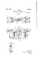
- Figure 1 is a plan view of the track illustrating a number of automobiles thereon and the feed system for .the con uctors embe ded in the track, and means for changing the voltage of different conductors.
- Figure 2 is a cross sectionon the line 22 of Fig. 1, taken in th direction of the arrows, illustrating-the conductors embed the electromagnets for reversing same, and
- Figure 4 is a plan view of the switch 1nstallation as if taken in the direction of the arrow 4: of Fig. 5.
- Figure 5 is'a side elevation of the switch I as if taken in the direction of the arrow 5 ofFig.4.'
- Figure 6 is a vertical sectlon on the hue 6-6 of Fig. 5 takenin the direction of the v arrows.
- Figure 7 is a plan view, artly broken away, of an automobile suita le for use in an amusement place.
- Figure 8 is a longitudinal sectlon of Fig.
- Figure 9 is a rear view of the automobile with the body structure broken away to show the mounting of the motor, the control switch, the shoes and theoperating wheels.
- the track is designated generally by the numeral 1 and may be of any suitable s ze for an amusement park or the like.
- the track has a series of conductors 2 embedded in the track, leaving non-conducting spaces 3.
- the adjacent conductors are of different polarity for a purpose hereunder set forth.
- the track may be made of any suitable shape and is shown in the drawings as being somewhat oblong with rounded ends.
- a series of feed wires 4 extend around the track and there are leads 5 from the feed wires to the conductors, these lead wires being led from the feed wires to the conductors at different spaces around the track, as indicated by the numerals 6 and 7.
- the power may be supplied by any suitable device and'is illustrated herein as having a di-, rect current generator 8 which may be operated by a suitable motor 9, the generator giving current of a comparatively low voltage, which I find a maximum of 32 volts satisfactory.
- a control 10 of any suitable character may be utilized to change the voltage in the difi'erent feed wires and hence in the different conductors so that there will be a variation in current supplied to these dif ferent conductors so that the automobiles in certain divisions on the track will travel faster than those in another division. It is to be understood that this control of the volt age may be mechanically operated if desired.
- the wiring arrangement and reversal 1switch is constructed substantially as folows:
- a series of conductors 2 are, as above men- 'tioned, alternatively positive and negative and are so indicated by the plus and minus signs in the diagram.
- the contact shoes 11, 12, 13 and 14, are suitably mounted on the vehicle as hereunder set forth.
- a walking beam type of switch is indicated generally by the numeral 15, the switch being mounted on a pivot 16, and having opposite arms 17, and a depending arm 18. Presuming the vehicle is in the. position illustrated in Fig. 3
- the current would be from such conductor through leads 19 and 20, a contact on the walking beam 21, a fixed contact 22, leads 23 and 24, to the motor 25.
- the lead circuit is by the leads 26 and 27 through a circuit breaker 28, hereunder described, a fixed contact 29, a movable contact 30, leads 31 and 32 to the shoe 11 on the negative conductor, thus the motoris energized and the vehicle driven.
- the energizing of the electromagnet 38 swings the walking beam breaking the contacts 21, 22, 29 and 30. A current would then flow from the positive conductor through the shoe 12, leads 41 and 42, the moving con tact 43, the fixed contact 44, leads 45 and 24, to the motor. The other side of the circuit is from the shoe 14, the leads 40 and 46, the moving contact 47, the fixed contact 48, leads 49 and 26, thus completing the circuit through the motor.
- the switch is again thrown in the following manner. Presuming the current passes through the shoe 13, the leads 19 and 50, to the contact 51 on the arm 18, the spring contact 52, the winding 53 of the electromagnet 54, and by. the return lead 55 to the Shoe 11, thus momentarily energizing the electromagnet 54, swinging the arms thereof to reestablish the circuit through the contacts 21, 22, 29 and 30, and breaking the opposite contacts.
- the walking beam switch is arranged by a toggle type of spring or other device so that the electroma nets are only required to give the initial t row or movement and this is continued by the spring and the walkingbeam arms held in the desired position by the spring. It will be noted that as soon as the walking beam switch is moved to establish the circuit on one side, it automatically breaks the circuit through .the electromagnet, thereby reducmg the consumption of current through such magnets.
- the mechanical construction of the switch is substantially as. follows, having reference particularly to Figs. 4, 5 and 6.
- a suitable framework is illustrated supporting the electromagnet-s 38 and 54 and in which the walking beam switch 15 is oscillatably mounted on a pivot pin 16 so that the opposite arms 17 extend in a horizontal direction and the arm 18 depends dbwnwardl
- the lower end of the arm 18 is engage by a toggle spring 56 so that the arm will be swung into opposite directions, after momentaril energizing either of the magnets, and eld in such position.
- the moving contacts 21 and 30 are indicated on one side and the moving contacts 43 and 47 on the other side .of the walking beam. These are shown as "These contacts are also on a resilient arm 58 and these arms have a bowed contact element 59 to engage with a contact plate 60 on the spring arm 61.
- the spring contacts 52 and 36 are illustrated by the spring structure of Fig. 5, the wiring, however, is omitted for the sake of clarifying said draw- 11] s.
- thearms 17 have the electrical featuresinsulated and have a suitable armature, which may be attracted by the energizing electromagnets.
- the spring 61 is bent into such a osition that when a contact is made the car on elements 57 engage before the contacts 59 and 60. However, when the switch is open the contacts 59 and 60 break first and the contacts between the carbons 57 subsequently. Therefore this construction of the two sets of contacts for the same electric circuit eliminates sparking in the making and breaking of the current. It is to be understood that the switch may be mounted in any suitable position in the automobile or other vehicle.
- a suitable type of vehicle isillustrated in Figs. 7, 8 and 9, in which the contact shoes 11, 12, 13 and 14, are indicated as being supported from a suitable bracket depending from the frame 66 of the vehicle.
- the electric motor 25 is preferably mounted on a frame back of the rear axle.
- the walking beam type of switch is indicated as being mountedback of the seat and the circuit breaker 28 is indicated as of a centrifugal type actuated from the motor shaft 67.
- the motor by means of a belt 68 or sprocket chain which is actuated from the shaft 67, drives a counter shaft 69 by means of a suitable pulley or sprocket 70, and from the counter shaft a chain or sprocket drive 71 leads to.
- a sprocket gear 72- direct-ly connected to one of the wheels 73.
- the vehicle is driven by one wheel, thus eliminating the use of a diiferential.
- the automobile has front steering wheels 74 actuated by the steering wheel 7 5, and is protected by side bumpers 76 over the front wheels, a front bumper 77, a rear bumper 78 which has side extensions 79 surrounding the-rear wheels and extending along the side of the vehicle. to a position adjacent the .of conductors spaced laterall bumpers 76.
- the automoblles may collide without injury to the vehicles or the occupants and as the can never travel at high speed there is but httle danger of accident.
- the operator of the vehicle can merely control the steering but not the amount of current his vehicle is receiving and, as he does not know which conductors have the greatest energy
- the spring contacts 36 and 52 maintain their engagement with the moving contacts '35 and 51 on the arm 18 until the arm has swung'pastthe dead center and then the toggle spring 56 completes the rest of the movement. It is also to -be noted that it is not necessary that the conductors on the track be flush with the surface of the track as these can be made of comparatively thin Ifnetal and' merely made on the track surace.
- An automobile riding device comprising in'combination, a track having a series tances apart, the conductors a ternating in polarity, a' vehicle having a plurality of equal dispairs of contact shoes, the shoes being equally spaced, an electric motor, a circuit between a pair of conductors through a pair of the shoes to the motor, and an electro magnetic device momentarily energized to make and break the motor circuit.
- An automobile riding device as claimed in claim 1, means to var the potential of certain conductors in re erence to others.
- An automobile riding device as claimed in claim 1, the track being continuous, and having means to feed the current to the conductors at a plurality of different gized, and a motor circuit between a pair of said shoes and the motor controlled by said switch.
- An automobile riding device as claimed in claim 4:, having a speed actuated make and break device in the motor circuit actuated by the motor to break the circuit on too great a speed of the motor.
- a vehicle having a plurality of pairs of contact shoes, an electric motor, a circuit between each pair of shoes and the motor, and an electromagnetic make and break device momentarily energized to control the motor circuit.
- An automobile riding device having a device actuated by the magnets to make an shoes, an electric motor to drive the vehicle,
- a pluralityof electromagnets a circuit from some of the shoes to the magnets having a make and break contact therein, a lIlOVlD break the magnet circuits, and means controlled by said device to make and break the motor circuits.
- a vehicle having a plurality of pairs of contact shoes, a plurality of electromagnets, a moving device having a pair of opposite arms and a depending arm, a circuit from each pair of shoes to a magnet having a make and break switch with one element on the depending arm, a magnet when energized operating said device to swing the arms and to make one circuit and break the circuit energized, and a plurality of contacts actuated by said arms to make and break the motor circuits.
- An automobile riding device comprising in combination, a continuous track having a series of conductors spaced laterally, the conductors being of alternate polarity, means to feed the current to the conductors at different positions around the track, means to vary the potential of different conductors in reference to others, a vehicle hav-' ing .an electric motor to drive same, a circuit between a pair of conductors and the motor, the vehicle having a plurality of contact shoes, an electromagnetically' operated switch having a plurality of electromagnetic devices energized momentarily to make and break the motor circuit.
Description
May 1, 1928 v F. s. RICH AUTOMOBILE RIDING AMUSEMENT DEVICE 4 Sheets-Sheet 1 Filed Dec. 13. 1926 May 1, 1928. I "1,668,249
, F. S. RICH AUTOMOBILE RIDING AMUSEMENT DEVICE Filed Dec. 1a. 1926 4 Sheets-Shet 2 I IS. Bt'c h. J W flzo l ii ys May 1, 1928. 1,668,249 F. s. RICH AUTOMOBILE RIDING AMUSEMENT DEVICE Filed Dec. 15. 1926 4 Shets-Sheet 3 I n; H II 4 l ml 21 -36 38 1 J2 In. u "'Hl ll I 6 M w UAW LLAJ 2720672 fr: j S. .5? [Ch f x M1 6% M fil ligyy May 1, 1928. 1,668,249
F. S. RICH AUTOMOBILE RIDING AMUSEMENT DEVICE I Filed Dec. 13, 1926 4 Sheets-Sheet 4 7 za 75' Z 79 Patented May 1, '1928.
UNITED STATES PATENT OFFICE.
FRANK S. RICH, 013 LOS ANGELES, CALIFORNIA, ASSIGNOR OI ONE-HALF '10 WILLIAI WELCH COCKINS AND ONE-HALF TO FRANK L. STIN-EMAN, BOTH Oil SANTA.
' MONICA, CALIFORNIA.
AUTOMOBILE RIDING annsnmnm' nnvrca;
Application filed December 13, 1926. serial 170. 154,488.
My invention is an-automobile riding device intended for amusement parks or thelike, in which a series of electric propelled automobiles may circulate on a track, the 5 steering of the automobiles being controlled by the driver, but the driver having no control over the power for operating the ma; chine except that he may run from one set of conductors ontoanother set.
An object of my invention is th'e construe tion of an automobile riding amusement device having a track with a series of pairs of conductors giving a feed and return circuit to operate electrically driven automobiles,-
the conductors being spaced apart transversely of the track. The automobiles are Y provided with two pairs of contact shoes and are, positioned relative to the conductors so that when travellin in alignment with the conductors there W1 1 be a pair of shoes in contact with a pair of conductors of opposite polarity, thus giving a feed and return circuitto the automobile. The conductors are spaced preferably so that if an automobile is steered to run out of contact I f. the conductors so that the voltag with one pair of conductors it may possibly bespaced so that none of the contacts used will engage the conductors, or another pair of shoes engage another pair of conductors thus supplying current to drive the car.
The conductorsare arranged to allow suflicient angular travel of the cars to run from one side of the track to the other and thereb engaging different sets of conductors, but
i the car is turned at too sharp an angle the shoes will lose contact -and therefore they will come to rest.
- Another object of my invention'is the construction of a track system with feeders'to of different ire of conductors'ma changed, there mobiles when they are in difierent portions of the track transversely of same. This adds to the amusement feature as the driver strives to find the sition on the track which will 've him t e test speed.
One of t e specific ofiject'sof my invention is the construction of an automobile switching device so that when the contact shoes engage the conductors of. difl'erent polarity, the switch will be operated'to convey any damage.
. showing dia rammaticall y giving difi'erent spee s to the auto-' and partlyside elevation.
electric great. The cars are equipped with bumpers on the sides, front and back, so that they may collide one with the other without doing A .further object of my invention is devising a system of conductors and control there for, together with suitable vehicles, and means of operating same so that low voltages ma be utilized permitting the attendants an travelers if necessary to walk upon the track and step on the conductors,
My lIIVBDtIOD in its various aspects will be more readily understood from the following description and. drawings, in which:
Figure 1 is a plan view of the track illustrating a number of automobiles thereon and the feed system for .the con uctors embe ded in the track, and means for changing the voltage of different conductors.
Figure 2 is a cross sectionon the line 22 of Fig. 1, taken in th direction of the arrows, illustrating-the conductors embed the electromagnets for reversing same, and
the circuits controlling the motor.
Figure 4 is a plan view of the switch 1nstallation as if taken in the direction of the arrow 4: of Fig. 5.
Figure 5 ,is'a side elevation of the switch I as if taken in the direction of the arrow 5 ofFig.4.'
Figure 6 is a vertical sectlon on the hue 6-6 of Fig. 5 takenin the direction of the v arrows.
Figure 7 is a plan view, artly broken away, of an automobile suita le for use in an amusement place.
Figure 8 is a longitudinal sectlon of Fig.
7 on the line 8-8, being partly in section Figure 9 is a rear view of the automobile with the body structure broken away to show the mounting of the motor, the control switch, the shoes and theoperating wheels.
Reference is first directed to the construction of the track, the installation of the conductors and the power supply, as illustrated particularly in Figs. 1 and 2. The track is designated generally by the numeral 1 and may be of any suitable s ze for an amusement park or the like. The track has a series of conductors 2 embedded in the track, leaving non-conducting spaces 3. The adjacent conductors are of different polarity for a purpose hereunder set forth. The track may be made of any suitable shape and is shown in the drawings as being somewhat oblong with rounded ends.
A series of feed wires 4 extend around the track and there are leads 5 from the feed wires to the conductors, these lead wires being led from the feed wires to the conductors at different spaces around the track, as indicated by the numerals 6 and 7. The power may be supplied by any suitable device and'is illustrated herein as having a di-, rect current generator 8 which may be operated by a suitable motor 9, the generator giving current of a comparatively low voltage, which I find a maximum of 32 volts satisfactory.
A control 10 of any suitable character, and illustrated as being regulated by an at tendant, may be utilized to change the voltage in the difi'erent feed wires and hence in the different conductors so that there will be a variation in current supplied to these dif ferent conductors so that the automobiles in certain divisions on the track will travel faster than those in another division. It is to be understood that this control of the volt age may be mechanically operated if desired.
The wiring arrangement and reversal 1switch is constructed substantially as folows:
Having reference particularly to Fig. 3, a series of conductors 2 are, as above men- 'tioned, alternatively positive and negative and are so indicated by the plus and minus signs in the diagram. The contact shoes 11, 12, 13 and 14, are suitably mounted on the vehicle as hereunder set forth. A walking beam type of switch is indicated generally by the numeral 15, the switch being mounted on a pivot 16, and having opposite arms 17, and a depending arm 18. Presuming the vehicle is in the. position illustrated in Fig. 3
with the shoe 13 on the positive conductor, the current would be from such conductor through leads 19 and 20, a contact on the walking beam 21, a fixed contact 22, leads 23 and 24, to the motor 25. The lead circuit is by the leads 26 and 27 through a circuit breaker 28, hereunder described, a fixed contact 29, a movable contact 30, leads 31 and 32 to the shoe 11 on the negative conductor, thus the motoris energized and the vehicle driven.
Presuming the driver steers his vehicle so that it moves to the right carrying the contact shoes to the ri ht, as shown in Fig. 3, then the shoe 12 wi 1 be in contact with the positive conductor which was engaged by the shoe 13 in the former case. The initial current passes through the leads 33 and 34, the contact 35 on the arm 18, the spring contact 36, the winding 37 on the electromagnet 38 having a core, leads 39 and 40 to the shoe 14 which will be in engagement with the negative conductor immediately to the right of such shoe.
The energizing of the electromagnet 38 swings the walking beam breaking the contacts 21, 22, 29 and 30. A current would then flow from the positive conductor through the shoe 12, leads 41 and 42, the moving con tact 43, the fixed contact 44, leads 45 and 24, to the motor. The other side of the circuit is from the shoe 14, the leads 40 and 46, the moving contact 47, the fixed contact 48, leads 49 and 26, thus completing the circuit through the motor.
If the automobile is then steered so that the shoes 11 and 13 again contact with any pair of conductors, which must be of opposite polarity, the switch is again thrown in the following manner. Presuming the current passes through the shoe 13, the leads 19 and 50, to the contact 51 on the arm 18, the spring contact 52, the winding 53 of the electromagnet 54, and by. the return lead 55 to the Shoe 11, thus momentarily energizing the electromagnet 54, swinging the arms thereof to reestablish the circuit through the contacts 21, 22, 29 and 30, and breaking the opposite contacts. The walking beam switch is arranged by a toggle type of spring or other device so that the electroma nets are only required to give the initial t row or movement and this is continued by the spring and the walkingbeam arms held in the desired position by the spring. It will be noted that as soon as the walking beam switch is moved to establish the circuit on one side, it automatically breaks the circuit through .the electromagnet, thereby reducmg the consumption of current through such magnets.
The mechanical construction of the switch is substantially as. follows, having reference particularly to Figs. 4, 5 and 6.
In these figuresa suitable framework is illustrated supporting the electromagnet- s 38 and 54 and in which the walking beam switch 15 is oscillatably mounted on a pivot pin 16 so that the opposite arms 17 extend in a horizontal direction and the arm 18 depends dbwnwardl The lower end of the arm 18 is engage by a toggle spring 56 so that the arm will be swung into opposite directions, after momentaril energizing either of the magnets, and eld in such position. In Fig. 4 the moving contacts 21 and 30 are indicated on one side and the moving contacts 43 and 47 on the other side .of the walking beam. These are shown as "These contacts are also on a resilient arm 58 and these arms have a bowed contact element 59 to engage with a contact plate 60 on the spring arm 61. The spring contacts 52 and 36 are illustrated by the spring structure of Fig. 5, the wiring, however, is omitted for the sake of clarifying said draw- 11] s.
I [n the operation of the walking beam switch thearms 17 have the electrical featuresinsulated and have a suitable armature, which may be attracted by the energizing electromagnets. The spring 61 is bent into such a osition that when a contact is made the car on elements 57 engage before the contacts 59 and 60. However, when the switch is open the contacts 59 and 60 break first and the contacts between the carbons 57 subsequently. Therefore this construction of the two sets of contacts for the same electric circuit eliminates sparking in the making and breaking of the current. It is to be understood that the switch may be mounted in any suitable position in the automobile or other vehicle.
A suitable type of vehicle isillustrated in Figs. 7, 8 and 9, in which the contact shoes 11, 12, 13 and 14, are indicated as being supported from a suitable bracket depending from the frame 66 of the vehicle. The electric motor 25 is preferably mounted on a frame back of the rear axle. The walking beam type of switch is indicated as being mountedback of the seat and the circuit breaker 28 is indicated as of a centrifugal type actuated from the motor shaft 67. The motor, by means of a belt 68 or sprocket chain which is actuated from the shaft 67, drives a counter shaft 69 by means of a suitable pulley or sprocket 70, and from the counter shaft a chain or sprocket drive 71 leads to. a sprocket gear 72- direct-ly connected to one of the wheels 73. The vehicle is driven by one wheel, thus eliminating the use of a diiferential.
The automobile has front steering wheels 74 actuated by the steering wheel 7 5, and is protected by side bumpers 76 over the front wheels, a front bumper 77, a rear bumper 78 which has side extensions 79 surrounding the-rear wheels and extending along the side of the vehicle. to a position adjacent the .of conductors spaced laterall bumpers 76. Thus protected, the automoblles may collide without injury to the vehicles or the occupants and as the can never travel at high speed there is but httle danger of accident.
From the above description of my invention, together with the drawings, it will be seen that I have developed an automobile riding amusement device in which the track system is provided with a series of conductors embedded in the surface of the track, adjacent conductors. being of different polarity. The current is fed to such conductors by a control device so that the voltage of different conductors may be changed either manually or by a mechanical construction. The current is also fed to the conductors at different positions around the track to prevent too great a drop in voltage,
" and hence current, should a majority of the vehicles be massed on one side.
The automobiles themselves have contact shoes positioned so that a feed and return circuit is substantially always established between a pair of such shoes and a pair of the adjacent conductors, provided the vehicle is running in a straight line on the tangent parts of the track or following a turn on the curve conforming to that of the conductors." The operator of the vehicle, as above mentioned, can merely control the steering but not the amount of current his vehicle is receiving and, as he does not know which conductors have the greatest energy,
he may travel from one side of the track to the other until he picks up the conductor which will give him the greatest speed or the slowest speed,'as desired. The automobiles colliding in traveling around the track adds zest to the enjoyment of the amusement and the patrons may either travel leisurely or have racing contests one with the other, in which the uncertainty of the rate of travel adds considerably to the amusement.
The spring contacts 36 and 52 maintain their engagement with the moving contacts '35 and 51 on the arm 18 until the arm has swung'pastthe dead center and then the toggle spring 56 completes the rest of the movement. It is also to -be noted that it is not necessary that the conductors on the track be flush with the surface of the track as these can be made of comparatively thin Ifnetal and' merely made on the track surace.
Various changes may be made in the principles of my invention without departing from the spiritthereof, as set forth in the description, drawings and claims:
I claim:
1. An automobile riding device comprising in'combination, a track having a series tances apart, the conductors a ternating in polarity, a' vehicle having a plurality of equal dispairs of contact shoes, the shoes being equally spaced, an electric motor, a circuit between a pair of conductors through a pair of the shoes to the motor, and an electro magnetic device momentarily energized to make and break the motor circuit.
2. An automobile riding device, as claimed in claim 1, means to var the potential of certain conductors in re erence to others.
3. An automobile riding device, as claimed in claim 1, the track being continuous, and having means to feed the current to the conductors at a plurality of different gized, and a motor circuit between a pair of said shoes and the motor controlled by said switch.
5. An automobile riding device, as claimed in claim 4:, having a speed actuated make and break device in the motor circuit actuated by the motor to break the circuit on too great a speed of the motor.
6. In an automobile riding device a vehicle having a plurality of pairs of contact shoes, an electric motor, a circuit between each pair of shoes and the motor, and an electromagnetic make and break device momentarily energized to control the motor circuit.
7. An automobile riding device having a device actuated by the magnets to make an shoes, an electric motor to drive the vehicle,
a pluralityof electromagnets, a circuit from some of the shoes to the magnets having a make and break contact therein, a lIlOVlD break the magnet circuits, and means controlled by said device to make and break the motor circuits.
8. In an automobile riding device a vehicle having a plurality of pairs of contact shoes, a plurality of electromagnets, a moving device having a pair of opposite arms and a depending arm, a circuit from each pair of shoes to a magnet having a make and break switch with one element on the depending arm, a magnet when energized operating said device to swing the arms and to make one circuit and break the circuit energized, and a plurality of contacts actuated by said arms to make and break the motor circuits. 7
9. An automobile riding device comprising in combination, a continuous track having a series of conductors spaced laterally, the conductors being of alternate polarity, means to feed the current to the conductors at different positions around the track, means to vary the potential of different conductors in reference to others, a vehicle hav-' ing .an electric motor to drive same, a circuit between a pair of conductors and the motor, the vehicle having a plurality of contact shoes, an electromagnetically' operated switch having a plurality of electromagnetic devices energized momentarily to make and break the motor circuit.
In testimony whereof I have signed my name to this specification.
FRANK S. RICH.
Priority Applications (1)
| Application Number | Priority Date | Filing Date | Title |
|---|---|---|---|
| US154489A US1668249A (en) | 1926-12-13 | 1926-12-13 | Automobile riding amusement device |
Applications Claiming Priority (1)
| Application Number | Priority Date | Filing Date | Title |
|---|---|---|---|
| US154489A US1668249A (en) | 1926-12-13 | 1926-12-13 | Automobile riding amusement device |
Publications (1)
| Publication Number | Publication Date |
|---|---|
| US1668249A true US1668249A (en) | 1928-05-01 |
Family
ID=22551541
Family Applications (1)
| Application Number | Title | Priority Date | Filing Date |
|---|---|---|---|
| US154489A Expired - Lifetime US1668249A (en) | 1926-12-13 | 1926-12-13 | Automobile riding amusement device |
Country Status (1)
| Country | Link |
|---|---|
| US (1) | US1668249A (en) |
Cited By (13)
| Publication number | Priority date | Publication date | Assignee | Title |
|---|---|---|---|---|
| US2631853A (en) * | 1950-06-09 | 1953-03-17 | Phillip J Haynes | Racing game apparatus |
| US2698180A (en) * | 1950-08-23 | 1954-12-28 | Joseph B Hersh | Racing game |
| US2717557A (en) * | 1948-12-22 | 1955-09-13 | Seyffer Robert | Electrically operated track for model vehicles |
| US2850987A (en) * | 1953-09-04 | 1958-09-09 | Edmond G Epergue | Limited two dimensional electric transmission system |
| US2899910A (en) * | 1959-08-18 | Amusement and educational device | ||
| US2962563A (en) * | 1954-09-03 | 1960-11-29 | Wilbur M Davis | Toy electric railway current collector means |
| US3228607A (en) * | 1965-05-12 | 1966-01-11 | Carl W Robinette | Electric trackway for toy vehicles |
| US3637956A (en) * | 1970-01-27 | 1972-01-25 | Robert D Blackman | Electricl automobile transportation system |
| US5868076A (en) * | 1996-02-28 | 1999-02-09 | Myus; David Allan | Slotless electric track for vehicles |
| US6244968B1 (en) | 1999-08-26 | 2001-06-12 | John Arie | Elevated wooden racetrack for go-karts and associated methods |
| FR2826917A1 (en) * | 2001-07-09 | 2003-01-10 | Jean Caillas | Electrical supply for karting track includes conductors accessible on track surface, with collecting runners on rear of vehicles |
| US10284012B2 (en) | 2015-05-06 | 2019-05-07 | Flag Acquisition, Llc | Systems and method for high power constellations for wireless charging and power delivery |
| US10843091B1 (en) | 2016-11-02 | 2020-11-24 | Brandon Paul | Amusement park attractions, amusement karts, and magnetic assemblies |
-
1926
- 1926-12-13 US US154489A patent/US1668249A/en not_active Expired - Lifetime
Cited By (16)
| Publication number | Priority date | Publication date | Assignee | Title |
|---|---|---|---|---|
| US2899910A (en) * | 1959-08-18 | Amusement and educational device | ||
| US2717557A (en) * | 1948-12-22 | 1955-09-13 | Seyffer Robert | Electrically operated track for model vehicles |
| US2631853A (en) * | 1950-06-09 | 1953-03-17 | Phillip J Haynes | Racing game apparatus |
| US2698180A (en) * | 1950-08-23 | 1954-12-28 | Joseph B Hersh | Racing game |
| US2850987A (en) * | 1953-09-04 | 1958-09-09 | Edmond G Epergue | Limited two dimensional electric transmission system |
| US2962563A (en) * | 1954-09-03 | 1960-11-29 | Wilbur M Davis | Toy electric railway current collector means |
| US3228607A (en) * | 1965-05-12 | 1966-01-11 | Carl W Robinette | Electric trackway for toy vehicles |
| US3637956A (en) * | 1970-01-27 | 1972-01-25 | Robert D Blackman | Electricl automobile transportation system |
| US5868076A (en) * | 1996-02-28 | 1999-02-09 | Myus; David Allan | Slotless electric track for vehicles |
| US6044767A (en) * | 1996-02-28 | 2000-04-04 | Myus; David Allan | Slotless electric track for vehicles |
| US6244968B1 (en) | 1999-08-26 | 2001-06-12 | John Arie | Elevated wooden racetrack for go-karts and associated methods |
| FR2826917A1 (en) * | 2001-07-09 | 2003-01-10 | Jean Caillas | Electrical supply for karting track includes conductors accessible on track surface, with collecting runners on rear of vehicles |
| US10284012B2 (en) | 2015-05-06 | 2019-05-07 | Flag Acquisition, Llc | Systems and method for high power constellations for wireless charging and power delivery |
| US10673277B2 (en) | 2015-05-06 | 2020-06-02 | Fli Charge, Llc | Systems and method for high power constellations for wireless charging and power delivery |
| US10843091B1 (en) | 2016-11-02 | 2020-11-24 | Brandon Paul | Amusement park attractions, amusement karts, and magnetic assemblies |
| US11369890B2 (en) | 2016-11-02 | 2022-06-28 | Brandon Paul | Amusement park attractions, amusement karts, and magnetic assemblies |
Similar Documents
| Publication | Publication Date | Title |
|---|---|---|
| US1668249A (en) | Automobile riding amusement device | |
| US3453970A (en) | Steerable toy vehicle | |
| US3797404A (en) | System for operating miniature vehicles | |
| US3314189A (en) | Remote, light actuated control means for models | |
| US3016024A (en) | Self-propelled reversing vehicle | |
| GB1390168A (en) | System for operating miniature vehicles | |
| US3041983A (en) | Toy monorail trolley systems | |
| US1587083A (en) | Electrically-driven toy vehicle | |
| US776826A (en) | Electric propulsion of cars or the like. | |
| US2632284A (en) | Toy electric railway car | |
| US1606691A (en) | Mobile tot | |
| US1877626A (en) | Railway traffic controlling system | |
| US3179063A (en) | Railway and road toy | |
| US1373108A (en) | Amusement apparatus | |
| US2920420A (en) | Toy automobile and track | |
| US8961262B2 (en) | Model motor vehicle highway system | |
| US1121988A (en) | Automatic control and sanding device for cars operating on slippery rails. | |
| US1588505A (en) | Testing apparatus or course | |
| US1489701A (en) | Amusement device | |
| US1400497A (en) | Amusement device | |
| US586652A (en) | Appaeatus foe woeking electeio teamways | |
| US1663971A (en) | Direction indicator | |
| US850173A (en) | Electric transportation system. | |
| US428098A (en) | Electric railway | |
| US425388A (en) | odell |