US3766331A - Hearing aid for producing sensations in the brain - Google Patents
Hearing aid for producing sensations in the brain Download PDFInfo
- Publication number
- US3766331A US3766331A US00201831A US3766331DA US3766331A US 3766331 A US3766331 A US 3766331A US 00201831 A US00201831 A US 00201831A US 3766331D A US3766331D A US 3766331DA US 3766331 A US3766331 A US 3766331A
- Authority
- US
- United States
- Prior art keywords
- sound
- sensation
- pulses
- signals
- recited
- Prior art date
- Legal status (The legal status is an assumption and is not a legal conclusion. Google has not performed a legal analysis and makes no representation as to the accuracy of the status listed.)
- Expired - Lifetime
Links
Images
Classifications
-
- A—HUMAN NECESSITIES
- A61—MEDICAL OR VETERINARY SCIENCE; HYGIENE
- A61F—FILTERS IMPLANTABLE INTO BLOOD VESSELS; PROSTHESES; DEVICES PROVIDING PATENCY TO, OR PREVENTING COLLAPSING OF, TUBULAR STRUCTURES OF THE BODY, e.g. STENTS; ORTHOPAEDIC, NURSING OR CONTRACEPTIVE DEVICES; FOMENTATION; TREATMENT OR PROTECTION OF EYES OR EARS; BANDAGES, DRESSINGS OR ABSORBENT PADS; FIRST-AID KITS
- A61F11/00—Methods or devices for treatment of the ears or hearing sense; Non-electric hearing aids; Methods or devices for enabling ear patients to achieve auditory perception through physiological senses other than hearing sense; Protective devices for the ears, carried on the body or in the hand
- A61F11/04—Methods or devices for enabling ear patients to achieve auditory perception through physiological senses other than hearing sense, e.g. through the touch sense
-
- A—HUMAN NECESSITIES
- A61—MEDICAL OR VETERINARY SCIENCE; HYGIENE
- A61N—ELECTROTHERAPY; MAGNETOTHERAPY; RADIATION THERAPY; ULTRASOUND THERAPY
- A61N1/00—Electrotherapy; Circuits therefor
- A61N1/18—Applying electric currents by contact electrodes
- A61N1/32—Applying electric currents by contact electrodes alternating or intermittent currents
- A61N1/36—Applying electric currents by contact electrodes alternating or intermittent currents for stimulation
- A61N1/36036—Applying electric currents by contact electrodes alternating or intermittent currents for stimulation of the outer, middle or inner ear
Definitions
- a pulsed oscillator or transmitter supplies energy to a [52] US. Cl 179/107 R P of insulated electrodes mounted on PBTSOIIS 51 Int. Cl H04r /00 neek-
- the transmitter produces pulses of intensity [58] Field of Search 128/21; /35 0; greater than a predetermined thresheld value and of a 179/107 R, 0 BC, 121 C, 15 340/407 width and rate so as to produce the sensation of hearing without use of the auditory canal thereby provid- 5 R f r Cited ing a hearing system enabling otherwise deaf people to UNITED STATES PATENTS 3,629,521 12/1971 Puharich et al 179/107 R 19 Claims, 14 Drawing Figures /6 fill/T68 AMP 72/6665 sums/2 SCH/W77 A0062 .2 F
- the present invention relates to means and techniques useful in conveying information and is particularly useful in hearing systems for otherwise deaf persons.
- the present invention is described in specific relation to systems enabling deaf persons to have communicated to them information initially in sound or audible form with such information being transformed into unique pulses that key a transmitter which develops a carrier above the audio frequency range, such carrier thus modulated being applied via insulated electrodes to excite a deaf persons cochlea such that the person has the sensation of hearing that information initially in sound or audible form.
- information in audible form is converted into a special form which is transmitted to appropriate areas of the brain. More specifically, such information is converted into essentially trigger pulses which are transmitted to the brain without the necessity of use of the persons auditory track, thereby in effect bypassing such auditory track. These trigger pulses are required to be of a predetermined threshold intensity below which intensity that part of the brain, considered the cochlea, is not excited.
- a pulse exceeds a predetermined intensity, its pulse width and its rate of occurrence may be used to create the sensations of frequency or tone and loudness.
- the cochlea is the electronic generator of the auditory system and that with normal hearing all signals reaching the cochlea are mechanical sound signals, and that not until the cells attached to the tectorial membrane are caused to oscillate does the conversion from mechanical to electronic take place.
- the auditory nerve system including the auditory transmission platform are excited in a novel way such that it functions to produce the desired electrical output without the necessity for the presence of the persons auditory track.
- a specific object of the present invention is to provide a system of this character which enables normally deaf persons to hear.
- Another object of the present invention is to provide a system of this character which does not depend upon operation of the persons auditory track.
- Another specific object of the present invention is to provide a system wherein information is conveyed to the cochlea in the form of coded pulses.
- FIGS. 2 and 3 illustrate one form of electrode arrangement used in the system shown in FIG. 1, FIG. 2 showing one of the two bands each mounting an electrode and FIG. 3 being a section as indicated by the line 3-3 in FIG. 2.
- FIG. 4 is a perspective view of one of two electrodes useful when the system illustrated in FIG. 1 operates at microwave frequencies.
- FIG. 5 illustrates the manner in which the electrodes of either FIGS. 2-3 or FIG. 4 may be mounted around the neck of the user and also illustrates schematically the equivalent capacitor and its association with the pulsed transmitter.
- FIGS. 6, 7 and 8 illustrate modified insulated electrode systems embodying features of the present invention which may be used in conjunction with the circuit shown in FIG. 1 or in conjunction with the circuit shown in FIG. 12.
- FIG. 9 illustrates the manner in which the electrode in FIG. 8 is used.
- FIG. l0 illustrates the manner in which the electrodes may be maintained pressed with the persons ear folded and maintained folded by the forces exerted by the electrode holders.
- FIG. 10A illustrates use of the device in connection with sealing of a persons ear E.
- FIG. 10B illustrates use of the device in connection with folding of the persons ear E.
- FIG. 11 illustrates a coupling system which may be used in conjunction with any one of the electrode systems described herein.
- FIG. 12 is a block diagram of an amplitude modulation system also embodying features of the present invention.
- the apparatus includes a conventional microphone l0 and audio amplifier 1 l for producing electrical currents or voltage outputs representative of the sound energy impinging on microphone 10. Such outputs are further amplified in each of three buffer amplifier stages l2, l3 and 14 having their corresponding outputs applied to the input circuit of trigger or pulse generators l6, l7 and 18 respectively. These generators may each be of the Schmitt type; Wave forms are also illustrated in FIG. 1; and for purposes of simplicity in explanation, the output 3 of the audio amplifier 11 is a sine wave having a frequency of 1,000 cycles per second. The output of amplifiers l2, l3 and 14 are also sine waves which may have the same intensity.
- the Schmitt triggers l6, l7, 18 are adjusted to become operative to develop a trigger only after the sine wave exceeds a predetermined threshold value.
- the Schmitt trigger circuit 18 develops a pulse for each cycle of such wave 3.
- the corresponding output of Schmitt trigger circuit 18 appears at 3A.
- Schmitt trigger circuit 17 is fired to develop trigger output pulse 4A.
- the intensity reaches or exceeds 2 volts as indicated by sine wave 5
- an output pulse per each sine wave cycle above 2 volts appears as indicated by pulse 5A.
- the pulses 3A, 4A, 5A are typical Schmitt pulses with some flat top portion and a negative spike. Pulses 4A and 5A are subjected to delay networks 48 and 58 respectively such that the undelayed pulses 3A and pulses 4A and 5A, delayed in different time amounts, appear at the intput of pulse adder and shaper as a train of waves.
- each of the multiplicity of trigger generators 16, 17, 19 is thus applied to a common pulse adder and shaper stage 20 where such outputs are combined and appear as a train pf pulses 24A prior to application to a modulator stage 24 which serves to key or modulate the output of the radio frequency transmitter stage 26 which incorporates an oscillator stage 28.
- This train of pulses 24A is preferably amplitude modulated to an extent greater than five percent prior to this application as a keying or modulating signal, and this is accomplished by applying the sine wave 3 to buffer amplitude 6 whose amplified output is applied through an amplitude modulation control in the form of an attenuating resistance network 7 to modulator 24 such that the keying signal then appears as an amplitude modulated keying signal 24A at the output of modulator 24.
- a keyed or pulsed radio frequency output appears across the primary winding of the coupling transformer 28 having one terminal of its secondary winding grounded and its other terminal connected to a pair of probes or electrodes 30, 30 which may be of the character described in FIGS. 2, 3 or FIG. 4 and applied to a persons neck as indicated in FIG. 5.
- the signal applied to such electrodes is in the form shown in exaggerated form at 28A which has generally the same envelope as the signal 24A with, however, the high frequency components or carrier within such envelope.
- one of the two neck straps is in the form of a flexible band or strap 40 having conventional metal strap fasteners 42, 43 on each end thereof for fastening cooperation with another like band (not shown).
- Each of such bands 40, 40 has secured to its central portion, an electrode or probe 30 constructed as shown in FIG. 3.
- Each electrode 30 is in the form of a platinum foil 50 which forms a circular wall of a cylindrical housing 52 to which a lead 53 is connected.
- Such housing 52 has a bolt stud portion 54 extending therefrom for attachment to the strap 40, using a nylon nut 56A for that purpose.
- the front side of such housing 52 is covered with an insulating material 56 so that there is no metal contacting the person s skin.
- more substantial solid metal electrodes may be used as, for example, a plating of precious metal over a solid base metal such as copper.
- each of the two coaxial cables 70 has its outer sheath, normally grounded, connected to a ring portion and its inner conductor connected to an inner disc portion which is maintained in spaced condition from ring 72 and disc portion 74 are covered with insulating material 78, 79 respectively, so that there is no metal contacting the persons neck.
- This assembly may be secured to a flexible strap as in FIG. 2 using a mounting stud bolt portion 80 secured to disc portion 79.
- the outer ring portion may be uninsulated and allowed to contact the persons skin.
- the auditory transmission platform is selective as to pulse width. After the triggering level is reached, it is believed that the width of the pulse determines the particular area of the platform stimulation-In general, a pulse of long duration stimulates low frequency areas; a pulse of shorter duration stimulates middle frequency areas, and a still shorter pulse is believed to stimulate high frequency areas.
- the'apparent loudness created by direct nerve cell stimulation as contemplated herein is related to the number of nerve cells that are stimulated, i.e., fired in a given area.
- the loudness sensation does not increase appreciably with pulse width (assuming that the pulse was sufficient to produce sensation) but does increase with the number of such pulses per unit time, i.e., the pulse repetition rate.
- pulse width assuming that the pulse was sufficient to produce sensation
- the pulse repetition rate i.e., the pulse repetition rate.
- the loudness sensation is not increased by merely increasing the size of this triggering pulse.
- the pulse repetition rate is changed.
- a pulse meeting the two conditions above and appearing at a rate of 1,000 pulses per second produces a certain loudness sensation and this loudness sensation may be increased by increasing the pulse repetition rate so that instead of appearing, for example, once every l/l000 second, it appears twice, three, four, etc. times every 1/1000 second depending upon the loudness of that 1,000 cycle per second sound applied to microphone 10.
- This loudness feature may be instrumented in FIG.
- the transmitter is keyed on and off-three times during the l/ 1000 second time interval which corresponds to the period of a 1,000 cycle per second signal.
- the amplitude modulating signal is the actual speech signal derived from amplifier 11 and that the actual pulse repetition rate of pulses which are derived from the adder and shaper 20 is higher than the speech frequency may by two to 10 times depending upon the number of trigger stages 16, I7, 18 which are used. As many as such trigger stages may be used with the output from each being separated in time by delay networks such that the pulses are added timewise as contrasted to amplitude wise. This relationship of two to 10 times mentioned above is substantially independent of the modulating sound frequency applied. via control 7 since it is noted again that a pulse is derived from each trigger circuit once per cycle of the alternating wave applied to a particular trigger circiut.
- the modulation control 7 is adjusted so that the signal from buffer amplifier 6 causes maximum sensation of sound over a 60 to 10,000 cycle per second frequency range. It has been observed that the high frequency response is improved using an amplitude modulating signal applied via control 7.
- the amplitude modulation imparted to the train of pulses is believed to cause desired ripple of the basilas membrane of the cochlear duct in that the shape of the train of pulses which is the result of amplitude modulation is believed to create what may be termed a positioning effect of sound in the cochlea.
- the amplitude modulated signals containing pulses are positioned over a specific area of the basilar membrane, and the pulses penetrate and cause nerve firing even in the absence of cochlear hairs or positive nerve action.
- the carrier frequency may be a low frequency signal, for example, the range of 60 kilocycles to 100 kilocycles in which case the units designated as 26 and 28 may be representatives of a power oscillator stage which is keyed on and off and which as indicated by the waveform 28A produces bursts of high frequency waves, the intensity of each succeeding wave thereof being slightly different and in accordance with the envelope established by the previously mentioned amplitude modulation.
- Operation in such frequency range of 60 to 100 kilocycles may be accomplished using electrodes 52. Operation may be accomplished at higher frequencies including microwave frequencies of, for example, 1,000 megacycles in which case electrodes of FIG. 4 are used. In either case, preferably the electrodes are connected to the same common output terminal such as terminal 30A with the other output terminal 308 being stabilized as, for example, by grounding of the same. This particular connection is considered important because it minimizes or eliminates tuning requirements. Indeed, when such electrodes are connected to a common output terminal, the associated high requency equipment need not be made adjustable, i.e., the high frequency equipment may be operated at a fixed frequency which is the same for different persons and different conditions. This is particularly true when the electrodes are insulated electrodes, i.e., have no metal energized part in contact with the skin of the person.
- the electrode of FIG. 3 may be incorporated as part of a larger assembly as shown in FIG. 6 wherein a power oscillator circuit (represented by units 26 and 28 in FIG. 1) is contained within an aluminum housing 100 and to which power is supplied lead 101, the modulating signal via lead 102 and a ground connection via lead or terminal 103.
- the lead 50A (FIG. 3) is internally connected to the oscillator circuit, and the metal plate 50 still remains insulated from the'user by insulating material 56.
- the electrode of FIG. 3 is modified such that a ground lead may be connected to a metal protrusion 11-1 and the person may then hold the insulated portion 56 against his skin or ear by applying pressure to ground terminal 111.
- This arrangement is particularly useful in stereo systems.
- FIG. 8 the electrode system of FIG. 3 is modified for mechanical attachment to the receiver housing portion of a conventional hand held telephone instru-v merit so that in normal use of the same as illustrated in FIG. 9, the nsulating cover sheet is pressed against the users ear.
- the electrode system of FIG. 3 may be hand held or mechanically secured to the person, as, for example, in FIG. 5, or a pair of the same may be on opposite legs 120, 121 of a conventional holder for earphones that maintains itself as a result of a tension or clamping section against the persons ears. As illustrated in FIG. 10. However, in this case using the electrode systems described herein, the ears are initially folded over prior to application of the tensioned holder 120,121, and sufficient tension is developed to maintain the ears in such folded condition, and the electrode 30 in position.
- the ear channel may be sealed by the electrodes contacting and pressing the cartilage portion at the front of the outer ear canal inwardly over the opening to such canal to thereby seal the canal.
- the folded ear coupling is illustrated in FIGS. 10A and 10B.
- the elctrode system of FIG. 6 may be hand held or holder held with or without the ear being folded over.
- the electrode system of FIG. 7 may be hand held with the ear being folded over with the ear being sealed or with the ear being open.
- FIG. 1 1 illustrates the use of a fluid filled plastic container between an electrode exemplified by the electrode of FIG. 7 and the persons ear.
- pressure is applied by the persons fingers engaging the metal grounded protrusion 111, the pressure being sufficient that the plastic container conforms to the geometry or shape of the persons ear.
- Such plastic container is preferably in the form of a hollow plastic container which is initially molded to the persons ear using techniques heretofor used in molding ear pieces.
- the mold is hollow and is filled with a fluid such as water and has mechanically secured thereto an electrode of the character of FIGS. 7 and 11.
- the use of such fluid filled intervening body results in increased useful output, this being considered to be due in part to improved tissue contact with the pinna (outer ear).
- Such intervening body may be of plastic of 0.003 inch thickness, as illustrated, and partly filled with water such that slight pressure causes it to press into the crevices and folds of the ear with the water serving as a conductor and providing a more ideal surface.
- the finger held protrusion 111 in FIG. 7 may instead of being metal may be of insulating material in which case there is no ground lead 110.
- the amplitude modulation system of FIG. 12 includes a source 10 of sound waves which are amplified in preamplifier and then applied to modulator l32 for amplitude modulating a power oscillator 134 whose amplitude modulated output is applied to the primary winding 136 of transformer 138 which has one terminal of its secondary winding 140 grounded and the other one of its terminals connected to a pair of electrode assemblies of, for example, the type shown in FIG. 7.
- the oscillator 134 may have a fixed frequency within, for example, the range of 60 to 100 kilohertz.
- An important advantage of such system is that the necessity of tuning of the oscillator to match the tissue impedance of different persons is obviated. This is due mainly to the connection of electrodes to the high side of the radio frequency recording winding 140 as illustrated in contrast to connecting electrodes directly across the secondary winding. Also contributing to this important advantage is the use of insulated electrodes. While the provision of metal protrusions of the character illustrated at 111 in FIG. 7 are not essential to the basic operation of the system of FIG.
- the entire amplitude modulation system' of FIG. 12 including, but not limited to, battery power supply and microphone may be completely housed in a single common metal housing 100 as typified in FIG. 6. Two of such housings 100 in a single headset may be used in a steeo system thus supplying one stereo channel information on one side and the other stereo channel information on the other side of the persons head.
- a method for providing the sensation of sound corresponding to sound waves in a subject comprising the steps of:
- a method for providing the sensation of sound corresponding to sound waves in a subject having an auditory nerve system comprising the steps of:
- intermediate frequency pulses from said audio frequency signals having a larger pulse repetition rate than said audio frequency signals, amplitude modulating said intermediate frequency pulses by said audio frequency signals to produce modulated intermediate frequency pulses, modulating the output of a high frequency generator by said modulated intermediate frequency pulses to produce modulated pulsed carrier signals, and couplingsaid modulated pulsed carrier signals to said subject for excitation of the auditory nerve system.
- a system for the production of the sense of sound in a persons body comprising:
- high frequency generator means for producing high frequency carrier waves having a pulse repetition rate substantially greater than the pulse repetition rate of the intermediate frequency pulses
- a system for the production of the sensation of sound in a persons body comprising:
- high frequency generator means having an output for producing high frequency carrier waves having a pulse repetition rate substantially greater than the pulse repetition rate of the modulated intermediate frequency pulses
Abstract
A pulsed oscillator or transmitter supplies energy to a pair of insulated electrodes mounted on a person''s neck. The transmitter produces pulses of intensity greater than a predetermined threshold value and of a width and rate so as to produce the sensation of hearing without use of the auditory canal thereby providing a hearing system enabling otherwise deaf people to hear.
Description
United States atent Zink 1 Oct. 16, 1973 [54] HEARING AID FOR PRODUCING 3,578,912 /197] Beavers, Jr. 169/15 A SENSATIONS IN THE BRAIN 3,170,993 2/1965 Puharich et a1. 179/107 BC 3,497,637 2/1970 Puharich et al 179/107 R [75] Invento Henry San Bernardmo, 3,586,791 6/1971 Puharich etal 179/107 R Calif. FOREIGN PATENTS OR APPLICATIONS [73] Assgnee g3? San Bemardm 278,833 /1927 Great Britain 169/121 c Filedl 1971 Primary ExaminerKathleen H. Claffy Assistant Examiner-Thomas L. Kundert 21 A 1. N 20183 1 pp 0 y 1 Attorney-Charles G. Lyon et a1.
Related US. Application Data [63] Continuation-impart of Ser. No. 847,292, Aug. 4, [57] ABSTRACT 1969, abandoned.
A pulsed oscillator or transmitter supplies energy to a [52] US. Cl 179/107 R P of insulated electrodes mounted on PBTSOIIS 51 Int. Cl H04r /00 neek- The transmitter produces pulses of intensity [58] Field of Search 128/21; /35 0; greater than a predetermined thresheld value and of a 179/107 R, 0 BC, 121 C, 15 340/407 width and rate so as to produce the sensation of hearing without use of the auditory canal thereby provid- 5 R f r Cited ing a hearing system enabling otherwise deaf people to UNITED STATES PATENTS 3,629,521 12/1971 Puharich et al 179/107 R 19 Claims, 14 Drawing Figures /6 fill/T68 AMP 72/6665 sums/2 SCH/W77 A0062 .2 F
AND Mowmrae yacrm/aas AMI. /6652 5MP 7ZA/V5. 30,
ear/ ee 50/14/77 54 W AME 72/6662 PATENTEDnm 15 I915 SHEET 2 OF 2 HEARING AID FOR PRODUCING SENSATIONS IN THE BRAIN The present application is a continuation-impart of my pending U.S. patent application, Ser. No. 847,292, filed Aug. 4, 1969 and now abandoned.
The present invention relates to means and techniques useful in conveying information and is particularly useful in hearing systems for otherwise deaf persons.
The present invention is described in specific relation to systems enabling deaf persons to have communicated to them information initially in sound or audible form with such information being transformed into unique pulses that key a transmitter which develops a carrier above the audio frequency range, such carrier thus modulated being applied via insulated electrodes to excite a deaf persons cochlea such that the person has the sensation of hearing that information initially in sound or audible form.
For these purposes, information in audible form is converted into a special form which is transmitted to appropriate areas of the brain. More specifically, such information is converted into essentially trigger pulses which are transmitted to the brain without the necessity of use of the persons auditory track, thereby in effect bypassing such auditory track. These trigger pulses are required to be of a predetermined threshold intensity below which intensity that part of the brain, considered the cochlea, is not excited.
It is considered that once a pulse exceeds a predetermined intensity, its pulse width and its rate of occurrence may be used to create the sensations of frequency or tone and loudness.
It is considered that the cochlea is the electronic generator of the auditory system and that with normal hearing all signals reaching the cochlea are mechanical sound signals, and that not until the cells attached to the tectorial membrane are caused to oscillate does the conversion from mechanical to electronic take place. As alluded to previously, the auditory nerve system including the auditory transmission platform are excited in a novel way such that it functions to produce the desired electrical output without the necessity for the presence of the persons auditory track.
It is therefore an object of the present invention to provide means and techniques incorporating these features.
A specific object of the present invention is to provide a system of this character which enables normally deaf persons to hear.
. Another object of the present invention is to provide a system of this character which does not depend upon operation of the persons auditory track.
Another specific object of the present invention is to provide a system wherein information is conveyed to the cochlea in the form of coded pulses.
The features of the present invention which are believed to be novel are set forth with particularity in the appended claims. This invention itself, both as to its organization and manner of operation, together with further objects and advantages thereof, may be best understood by reference to the following description taken in connection with the accompanying drawings bodying features of the present invention for practicing novel concepts and achieving new results also in accordance with features of the present invention.
FIGS. 2 and 3 illustrate one form of electrode arrangement used in the system shown in FIG. 1, FIG. 2 showing one of the two bands each mounting an electrode and FIG. 3 being a section as indicated by the line 3-3 in FIG. 2.
FIG. 4 is a perspective view of one of two electrodes useful when the system illustrated in FIG. 1 operates at microwave frequencies.
FIG. 5 illustrates the manner in which the electrodes of either FIGS. 2-3 or FIG. 4 may be mounted around the neck of the user and also illustrates schematically the equivalent capacitor and its association with the pulsed transmitter.
FIGS. 6, 7 and 8 illustrate modified insulated electrode systems embodying features of the present invention which may be used in conjunction with the circuit shown in FIG. 1 or in conjunction with the circuit shown in FIG. 12.
FIG. 9 illustrates the manner in which the electrode in FIG. 8 is used.
FIG. l0 illustrates the manner in which the electrodes may be maintained pressed with the persons ear folded and maintained folded by the forces exerted by the electrode holders.
FIG. 10A illustrates use of the device in connection with sealing of a persons ear E.
FIG. 10B illustrates use of the device in connection with folding of the persons ear E.
FIG. 11 illustrates a coupling system which may be used in conjunction with any one of the electrode systems described herein.
FIG. 12 is a block diagram of an amplitude modulation system also embodying features of the present invention.
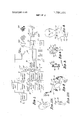
In FIG. 1, the apparatus includes a conventional microphone l0 and audio amplifier 1 l for producing electrical currents or voltage outputs representative of the sound energy impinging on microphone 10. Such outputs are further amplified in each of three buffer amplifier stages l2, l3 and 14 having their corresponding outputs applied to the input circuit of trigger or pulse generators l6, l7 and 18 respectively. These generators may each be of the Schmitt type; Wave forms are also illustrated in FIG. 1; and for purposes of simplicity in explanation, the output 3 of the audio amplifier 11 is a sine wave having a frequency of 1,000 cycles per second. The output of amplifiers l2, l3 and 14 are also sine waves which may have the same intensity. However, the Schmitt triggers l6, l7, 18 are adjusted to become operative to develop a trigger only after the sine wave exceeds a predetermined threshold value. Thus when the intensity exceeds, for example, volt as represented by sine wave 3, the Schmitt trigger circuit 18 develops a pulse for each cycle of such wave 3. The corresponding output of Schmitt trigger circuit 18 appears at 3A. Likewise, when the intensity of the sine wave exceeds the illustrated one voltwave 4, Schmitt trigger circuit 17 is fired to develop trigger output pulse 4A. Similarly, when the intensity reaches or exceeds 2 volts as indicated by sine wave 5, an output pulse per each sine wave cycle above 2 volts appears as indicated by pulse 5A. The pulses 3A, 4A, 5A are typical Schmitt pulses with some flat top portion and a negative spike. Pulses 4A and 5A are subjected to delay networks 48 and 58 respectively such that the undelayed pulses 3A and pulses 4A and 5A, delayed in different time amounts, appear at the intput of pulse adder and shaper as a train of waves.
The output of each of the multiplicity of trigger generators 16, 17, 19 is thus applied to a common pulse adder and shaper stage 20 where such outputs are combined and appear as a train pf pulses 24A prior to application to a modulator stage 24 which serves to key or modulate the output of the radio frequency transmitter stage 26 which incorporates an oscillator stage 28. This train of pulses 24A is preferably amplitude modulated to an extent greater than five percent prior to this application as a keying or modulating signal, and this is accomplished by applying the sine wave 3 to buffer amplitude 6 whose amplified output is applied through an amplitude modulation control in the form of an attenuating resistance network 7 to modulator 24 such that the keying signal then appears as an amplitude modulated keying signal 24A at the output of modulator 24. A keyed or pulsed radio frequency output appears across the primary winding of the coupling transformer 28 having one terminal of its secondary winding grounded and its other terminal connected to a pair of probes or electrodes 30, 30 which may be of the character described in FIGS. 2, 3 or FIG. 4 and applied to a persons neck as indicated in FIG. 5. The signal applied to such electrodes is in the form shown in exaggerated form at 28A which has generally the same envelope as the signal 24A with, however, the high frequency components or carrier within such envelope.
In FIG. 2 one of the two neck straps is in the form of a flexible band or strap 40 having conventional metal strap fasteners 42, 43 on each end thereof for fastening cooperation with another like band (not shown). Each of such bands 40, 40 has secured to its central portion, an electrode or probe 30 constructed as shown in FIG. 3. Each electrode 30 is in the form of a platinum foil 50 which forms a circular wall of a cylindrical housing 52 to which a lead 53 is connected. Such housing 52 has a bolt stud portion 54 extending therefrom for attachment to the strap 40, using a nylon nut 56A for that purpose. The front side of such housing 52 is covered with an insulating material 56 so that there is no metal contacting the person s skin. Instead of thin foil, more substantial solid metal electrodes may be used as, for example, a plating of precious metal over a solid base metal such as copper.
The use of insulating material 56 in these probes or electrodes results in an electrical capacity which is represented by the capacitor 60 in FIG. 5 which in effect is connected across the terminals of the secondary winding of coupling transformer 28.
When operation is at microwave frequencies, the two probes or electrodes may be in the form shown in FIG. 4 wherein each of the two coaxial cables 70 has its outer sheath, normally grounded, connected to a ring portion and its inner conductor connected to an inner disc portion which is maintained in spaced condition from ring 72 and disc portion 74 are covered with insulating material 78, 79 respectively, so that there is no metal contacting the persons neck. This assembly may be secured to a flexible strap as in FIG. 2 using a mounting stud bolt portion 80 secured to disc portion 79. In some cases the outer ring portion may be uninsulated and allowed to contact the persons skin.
It is presently believed that the auditory transmission platform is selective as to pulse width. After the triggering level is reached, it is believed that the width of the pulse determines the particular area of the platform stimulation-In general, a pulse of long duration stimulates low frequency areas; a pulse of shorter duration stimulates middle frequency areas, and a still shorter pulse is believed to stimulate high frequency areas.
There are further indications that the'apparent loudness created by direct nerve cell stimulation as contemplated herein is related to the number of nerve cells that are stimulated, i.e., fired in a given area. The loudness sensation does not increase appreciably with pulse width (assuming that the pulse was sufficient to produce sensation) but does increase with the number of such pulses per unit time, i.e., the pulse repetition rate. Thus, for example, considering a 1,000 cycle sine wave a person will have the hearing sensation of a 1,000 cycle per second wave when two conditions are achieved; namely, (1) the pulse applied to his auditory nerve system is above a predetermined threshold level sufficient to fire nerve cells and (2) the pulse so applied has a characteristic width corresponding to 1,000 cycles per second. The loudness sensation is not increased by merely increasing the size of this triggering pulse. To increase loudness, the pulse repetition rate is changed. Thus, for example, a pulse meeting the two conditions above and appearing at a rate of 1,000 pulses per second produces a certain loudness sensation and this loudness sensation may be increased by increasing the pulse repetition rate so that instead of appearing, for example, once every l/l000 second, it appears twice, three, four, etc. times every 1/1000 second depending upon the loudness of that 1,000 cycle per second sound applied to microphone 10. This loudness feature may be instrumented in FIG. 1 by, for example, providing more than one trigger generator as illustrated and adjusting the level of such generators such that with increasing output signals at the three identical buffer stages 12, 13, 14 the trigger generators are progressively triggered or fired with the result that when a signal representing medium loudness is present, two such trigger generators are triggered and when the intensity of such output signal increases further the third trigger generator is triggered thereby supplying another identical pulse to the adder circuit. In this last case the transmitter is keyed on and off-three times during the l/ 1000 second time interval which corresponds to the period of a 1,000 cycle per second signal.
As to change in pulse width with frequency, this is accomplished through inherent operation of the exemplified trigger forming network since it is well recognized that the pulse duration of a pulse developed by applying a low frequency sine wave is greater than the pulse width of a pulse initiated by a higher frequency sine wave.
While apparatus built without a buffer amplifier 6 and a modulator control inherently produces some amplitude modulation of the pulse trains 24A amounting to approximately five percent amplitude modulation, it has been found that improved overall system operation is accomplished when the percentage of modulation is increased and preferably the percentage of modulation is within the range of 20 to 50 percent.
It is observed that the amplitude modulating signal is the actual speech signal derived from amplifier 11 and that the actual pulse repetition rate of pulses which are derived from the adder and shaper 20 is higher than the speech frequency may by two to 10 times depending upon the number of trigger stages 16, I7, 18 which are used. As many as such trigger stages may be used with the output from each being separated in time by delay networks such that the pulses are added timewise as contrasted to amplitude wise. This relationship of two to 10 times mentioned above is substantially independent of the modulating sound frequency applied. via control 7 since it is noted again that a pulse is derived from each trigger circuit once per cycle of the alternating wave applied to a particular trigger circiut.
In general the modulation control 7 is adjusted so that the signal from buffer amplifier 6 causes maximum sensation of sound over a 60 to 10,000 cycle per second frequency range. It has been observed that the high frequency response is improved using an amplitude modulating signal applied via control 7.
The amplitude modulation imparted to the train of pulses is believed to cause desired ripple of the basilas membrane of the cochlear duct in that the shape of the train of pulses which is the result of amplitude modulation is believed to create what may be termed a positioning effect of sound in the cochlea. In accordance with this belief and theory, the amplitude modulated signals containing pulses are positioned over a specific area of the basilar membrane, and the pulses penetrate and cause nerve firing even in the absence of cochlear hairs or positive nerve action.
As alluded to previously, the carrier frequency may be a low frequency signal, for example, the range of 60 kilocycles to 100 kilocycles in which case the units designated as 26 and 28 may be representatives of a power oscillator stage which is keyed on and off and which as indicated by the waveform 28A produces bursts of high frequency waves, the intensity of each succeeding wave thereof being slightly different and in accordance with the envelope established by the previously mentioned amplitude modulation.
Operation in such frequency range of 60 to 100 kilocycles may be accomplished using electrodes 52. Operation may be accomplished at higher frequencies including microwave frequencies of, for example, 1,000 megacycles in which case electrodes of FIG. 4 are used. In either case, preferably the electrodes are connected to the same common output terminal such as terminal 30A with the other output terminal 308 being stabilized as, for example, by grounding of the same. This particular connection is considered important because it minimizes or eliminates tuning requirements. Indeed, when such electrodes are connected to a common output terminal, the associated high requency equipment need not be made adjustable, i.e., the high frequency equipment may be operated at a fixed frequency which is the same for different persons and different conditions. This is particularly true when the electrodes are insulated electrodes, i.e., have no metal energized part in contact with the skin of the person.
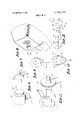
The electrode of FIG. 3 may be incorporated as part of a larger assembly as shown in FIG. 6 wherein a power oscillator circuit (represented by units 26 and 28 in FIG. 1) is contained within an aluminum housing 100 and to which power is supplied lead 101, the modulating signal via lead 102 and a ground connection via lead or terminal 103. In this case, the lead 50A (FIG. 3) is internally connected to the oscillator circuit, and the metal plate 50 still remains insulated from the'user by insulating material 56.
In FIG. 7 the electrode of FIG. 3 is modified such that a ground lead may be connected to a metal protrusion 11-1 and the person may then hold the insulated portion 56 against his skin or ear by applying pressure to ground terminal 111. This arrangement is particularly useful in stereo systems.
In FIG. 8 the electrode system of FIG. 3 is modified for mechanical attachment to the receiver housing portion of a conventional hand held telephone instru-v merit so that in normal use of the same as illustrated in FIG. 9, the nsulating cover sheet is pressed against the users ear.
The electrode system of FIG. 3 may be hand held or mechanically secured to the person, as, for example, in FIG. 5, or a pair of the same may be on opposite legs 120, 121 of a conventional holder for earphones that maintains itself as a result of a tension or clamping section against the persons ears. As illustrated in FIG. 10. However, in this case using the electrode systems described herein, the ears are initially folded over prior to application of the tensioned holder 120,121, and sufficient tension is developed to maintain the ears in such folded condition, and the electrode 30 in position. Instead of the ear channel being closed by the folded ear, the ear channel may be sealed by the electrodes contacting and pressing the cartilage portion at the front of the outer ear canal inwardly over the opening to such canal to thereby seal the canal. The folded ear coupling is illustrated in FIGS. 10A and 10B.
Likewise, the elctrode system of FIG. 6 may be hand held or holder held with or without the ear being folded over.
The electrode system of FIG. 7 may be hand held with the ear being folded over with the ear being sealed or with the ear being open.
FIG. 1 1 illustrates the use of a fluid filled plastic container between an electrode exemplified by the electrode of FIG. 7 and the persons ear. In use, pressure is applied by the persons fingers engaging the metal grounded protrusion 111, the pressure being sufficient that the plastic container conforms to the geometry or shape of the persons ear. Such plastic container is preferably in the form of a hollow plastic container which is initially molded to the persons ear using techniques heretofor used in molding ear pieces. In this instances, the mold is hollow and is filled with a fluid such as water and has mechanically secured thereto an electrode of the character of FIGS. 7 and 11. The use of such fluid filled intervening body results in increased useful output, this being considered to be due in part to improved tissue contact with the pinna (outer ear). Such intervening body may be of plastic of 0.003 inch thickness, as illustrated, and partly filled with water such that slight pressure causes it to press into the crevices and folds of the ear with the water serving as a conductor and providing a more ideal surface.
In some cases the finger held protrusion 111 in FIG. 7 may instead of being metal may be of insulating material in which case there is no ground lead 110.
The amplitude modulation system of FIG. 12 includes a source 10 of sound waves which are amplified in preamplifier and then applied to modulator l32 for amplitude modulating a power oscillator 134 whose amplitude modulated output is applied to the primary winding 136 of transformer 138 which has one terminal of its secondary winding 140 grounded and the other one of its terminals connected to a pair of electrode assemblies of, for example, the type shown in FIG. 7.
The oscillator 134 may have a fixed frequency within, for example, the range of 60 to 100 kilohertz. An important advantage of such system is that the necessity of tuning of the oscillator to match the tissue impedance of different persons is obviated. This is due mainly to the connection of electrodes to the high side of the radio frequency recording winding 140 as illustrated in contrast to connecting electrodes directly across the secondary winding. Also contributing to this important advantage is the use of insulated electrodes. While the provision of metal protrusions of the character illustrated at 111 in FIG. 7 are not essential to the basic operation of the system of FIG. 12, they are preferred in some instances because when contacted by the persons fingers or other exposed skin areas, thus effectively grounding the person, the intensity of received information is increased by, for example, in some cases decibels without destroying the previousy mentioned advantage of not requiring a returning of the oscillator.
It is noted that the entire amplitude modulation system' of FIG. 12 including, but not limited to, battery power supply and microphone may be completely housed in a single common metal housing 100 as typified in FIG. 6. Two of such housings 100 in a single headset may be used in a steeo system thus supplying one stereo channel information on one side and the other stereo channel information on the other side of the persons head.
While the particular embodiments of the present invention have been shown and described, it will be obvious to those skilled in the art that changes and modifications may be made without departing from the invention in its broader aspects and, therefore, the aim in the appended claims is to cover all such changes and modifications as fall within the true spirit and scope of this invention.
I claim:
l. A method for providing the sensation of sound corresponding to sound waves in a subject comprising the steps of:
generating audio frequency signals corresponding to said sound waves,
generating high frequency carrier signal from a high frequency generator, transforming said audio frequency signals into pulses having a pulse repitition rate corresponding to the amplitude of each of said audio frequency signals,
modulating said carrier signal by said pulses and amplitude modulating said carrier signal by said audio frequency signals thereby producing amplitude modulated pulsed carrier signals, and
coupling said amplitude modulated pulsed carrier signals to said subject for producing the sensation of sound.
2. A method for providing the sensation of sound as recited in claim 1 in which said coupling is a nonconductive coupling to said subject.
3. A method for providing the sensation of sound as recited in claim 1 wherein said subject is a person having an ear canal and said coupling includes sealing said ear canal.
4. A method for providing the sensation of sound as recited in claim 1 wherein said subject is a person having an ear canal and wherein said coupling includes pressing an outer electrode carrying said amplitude modulated pulsed carrier signal against the persons folded ear.
5. A method for providing the sensation of sound as recited in claim 1 wherein said coupling is accomplished using two electrodes, each connected to the same output terminal of a source of said amplitude modulated pulsed carrier signals with the other output terminal of said source being grounded.
6. A method for providing the sensation of sound as recited in claim 1 in which said coupling is accomplished via an ear mold filled with a conductive solution.
7. A method for providing the sensation of sound as recited in claim 1 wherein said coupling is accomplished via a container of insulating material filled with a fluid through which said signal is applied to said body.
8. A method for providing the sensation of sound as recited in claim 1 wherein said amplitude modulation is within the range of 10 to 60 per cent.
9. A method for providing the sensation of sound as recited in claim 1 wherein the pulse repetition rate of said pulses is approximately two to 10 times the frequency of said audio frequency signals.
10. A method for providing the sensation of sound as recited in claim 1 wherein the coupling is provided by an insulated electrode to which said amplitude modulated pulsed carrier signals are applied.
11. A method for providing the sensation of sound as recited in claim 10 in which said electrode is part of a mechanical, hand-held assembly having a grounded metallic element contactable by a persons finger.
12. A method for providing the sensation of sound as recited in claim 1 wherein the coupling is provided by an insulated electrode mounted on a telephone receiver.
13. A method for providing the sensation of sound corresponding to sound waves in a subject having an auditory nerve system comprising the steps of:
generating audio frequency signals corresponding to said sound waves,
generating intermediate frequency pulses from said audio frequency signals having a larger pulse repetition rate than said audio frequency signals, amplitude modulating said intermediate frequency pulses by said audio frequency signals to produce modulated intermediate frequency pulses, modulating the output of a high frequency generator by said modulated intermediate frequency pulses to produce modulated pulsed carrier signals, and couplingsaid modulated pulsed carrier signals to said subject for excitation of the auditory nerve system.
14. A method for providing the sensation of sound as recited in claim 13 wherein the pulse repetition rate of said modulated pulses corresponds to the amplitude of said audio frequency signals.
15. A method for providing the sensation of sound as recited in claim 14 wherein the pulsed repetition rate of said modulated pulses .is approximately two to 10 times the frequency of said audio frequency signals.
16. A system for the production of the sense of sound in a persons body comprising:
means for converting sound waves into audio frequency signals, means connected to said converting means for generating intermediate frequency pulses having a pulsed repetition rate greater than said audio frequency signals,
high frequency generator means for producing high frequency carrier waves having a pulse repetition rate substantially greater than the pulse repetition rate of the intermediate frequency pulses,
means connected to said high frequency generator means for modulating said carrier waves by said intermediate frequency pulses and for amplitude modulating said carrier waves by said audio frequency signals to produce modulated pulsed carrier signals, and
means for coupling said modulated pulsed carrier signals to said persons body whereby the sensation of sound corresponding to sound waves is produced.
17. A system as recited in claim 16 wherein said coupling means includes an electrode and insulation for insulating said electrode from the persons body.
18. A system as recited in claim 17 wherein said electrode forms part of a hand-held device having a grounded element for contact with the persons finger.
19. A system for the production of the sensation of sound in a persons body comprising:
means for converting sound waves into audio frequency signals,
means connected to said converting means for generating intermediate frequency pulses having a pulsed repetition rate greater than said audio frequency signals,
means for amplitude modulating said intermediate frequency pulses by said audio frequency signals to produce modulated intermediate frequency pulses,
high frequency generator means having an output for producing high frequency carrier waves having a pulse repetition rate substantially greater than the pulse repetition rate of the modulated intermediate frequency pulses,
means connected to said high frequency generator output for modulating said carrier waves by said modulated intermediate frequency pulses to produce modulated pulsed carrier signals, and
means for coupling said modulated pulsed carrier signals to said persons body whereby the sensation of sound corresponding to sound waves is produced.
Claims (19)
1. A method for providiNg the sensation of sound corresponding to sound waves in a subject comprising the steps of: generating audio frequency signals corresponding to said sound waves, generating high frequency carrier signal from a high frequency generator, transforming said audio frequency signals into pulses having a pulse repitition rate corresponding to the amplitude of each of said audio frequency signals, modulating said carrier signal by said pulses and amplitude modulating said carrier signal by said audio frequency signals thereby producing amplitude modulated pulsed carrier signals, and coupling said amplitude modulated pulsed carrier signals to said subject for producing the sensation of sound.
2. A method for providing the sensation of sound as recited in claim 1 in which said coupling is a non-conductive coupling to said subject.
3. A method for providing the sensation of sound as recited in claim 1 wherein said subject is a person having an ear canal and said coupling includes sealing said ear canal.
4. A method for providing the sensation of sound as recited in claim 1 wherein said subject is a person having an ear canal and wherein said coupling includes pressing an outer electrode carrying said amplitude modulated pulsed carrier signal against the person''s folded ear.
5. A method for providing the sensation of sound as recited in claim 1 wherein said coupling is accomplished using two electrodes, each connected to the same output terminal of a source of said amplitude modulated pulsed carrier signals with the other output terminal of said source being grounded.
6. A method for providing the sensation of sound as recited in claim 1 in which said coupling is accomplished via an ear mold filled with a conductive solution.
7. A method for providing the sensation of sound as recited in claim 1 wherein said coupling is accomplished via a container of insulating material filled with a fluid through which said signal is applied to said body.
8. A method for providing the sensation of sound as recited in claim 1 wherein said amplitude modulation is within the range of 10 to 60 per cent.
9. A method for providing the sensation of sound as recited in claim 1 wherein the pulse repetition rate of said pulses is approximately two to 10 times the frequency of said audio frequency signals.
10. A method for providing the sensation of sound as recited in claim 1 wherein the coupling is provided by an insulated electrode to which said amplitude modulated pulsed carrier signals are applied.
11. A method for providing the sensation of sound as recited in claim 10 in which said electrode is part of a mechanical, hand-held assembly having a grounded metallic element contactable by a person''s finger.
12. A method for providing the sensation of sound as recited in claim 1 wherein the coupling is provided by an insulated electrode mounted on a telephone receiver.
13. A method for providing the sensation of sound corresponding to sound waves in a subject having an auditory nerve system comprising the steps of: generating audio frequency signals corresponding to said sound waves, generating intermediate frequency pulses from said audio frequency signals having a larger pulse repetition rate than said audio frequency signals, amplitude modulating said intermediate frequency pulses by said audio frequency signals to produce modulated intermediate frequency pulses, modulating the output of a high frequency generator by said modulated intermediate frequency pulses to produce modulated pulsed carrier signals, and coupling said modulated pulsed carrier signals to said subject for excitation of the auditory nerve system.
14. A method for providing the sensation of sound as recited in claim 13 wherein the pulse repetition rate of said modulated pulses corresponds to the amplitude of said audio frequency signals.
15. A method for providing the sensation of sound as recited in claim 14 wherein the pulsed repetition rate of said modulated pulses is approximately two to 10 times the frequency of said audio frequency signals.
16. A system for the production of the sense of sound in a person''s body comprising: means for converting sound waves into audio frequency signals, means connected to said converting means for generating intermediate frequency pulses having a pulsed repetition rate greater than said audio frequency signals, high frequency generator means for producing high frequency carrier waves having a pulse repetition rate substantially greater than the pulse repetition rate of the intermediate frequency pulses, means connected to said high frequency generator means for modulating said carrier waves by said intermediate frequency pulses and for amplitude modulating said carrier waves by said audio frequency signals to produce modulated pulsed carrier signals, and means for coupling said modulated pulsed carrier signals to said person''s body whereby the sensation of sound corresponding to sound waves is produced.
17. A system as recited in claim 16 wherein said coupling means includes an electrode and insulation for insulating said electrode from the person''s body.
18. A system as recited in claim 17 wherein said electrode forms part of a hand-held device having a grounded element for contact with the person''s finger.
19. A system for the production of the sensation of sound in a person''s body comprising: means for converting sound waves into audio frequency signals, means connected to said converting means for generating intermediate frequency pulses having a pulsed repetition rate greater than said audio frequency signals, means for amplitude modulating said intermediate frequency pulses by said audio frequency signals to produce modulated intermediate frequency pulses, high frequency generator means having an output for producing high frequency carrier waves having a pulse repetition rate substantially greater than the pulse repetition rate of the modulated intermediate frequency pulses, means connected to said high frequency generator output for modulating said carrier waves by said modulated intermediate frequency pulses to produce modulated pulsed carrier signals, and means for coupling said modulated pulsed carrier signals to said person''s body whereby the sensation of sound corresponding to sound waves is produced.
Applications Claiming Priority (1)
| Application Number | Priority Date | Filing Date | Title |
|---|---|---|---|
| US20183171A | 1971-11-24 | 1971-11-24 |
Publications (1)
| Publication Number | Publication Date |
|---|---|
| US3766331A true US3766331A (en) | 1973-10-16 |
Family
ID=22747487
Family Applications (1)
| Application Number | Title | Priority Date | Filing Date |
|---|---|---|---|
| US00201831A Expired - Lifetime US3766331A (en) | 1971-11-24 | 1971-11-24 | Hearing aid for producing sensations in the brain |
Country Status (2)
| Country | Link |
|---|---|
| US (1) | US3766331A (en) |
| BE (1) | BE802409A (en) |
Cited By (11)
| Publication number | Priority date | Publication date | Assignee | Title |
|---|---|---|---|---|
| US4368459A (en) * | 1980-12-16 | 1983-01-11 | Robert Sapora | Educational apparatus and method for control of deaf individuals in a mixed teaching environment |
| US4813419A (en) * | 1984-11-07 | 1989-03-21 | Mcconnell Jeffrey D | Method and apparatus for communicating information representative of sound waves to the deaf |
| US4877027A (en) * | 1988-06-06 | 1989-10-31 | Brunkan Wayne B | Hearing system |
| US4938223A (en) * | 1988-03-28 | 1990-07-03 | T. H. Charters, Inc. | Transcutaneous nerve block device |
| US4947844A (en) * | 1984-09-07 | 1990-08-14 | The University Of Melbourne | Receiver/stimulator for hearing prosthesis |
| WO1992009251A1 (en) * | 1990-11-28 | 1992-06-11 | Canadian Bionic Research, Inc. | Communication device for transmitting audio information to a user |
| US5215085A (en) * | 1988-06-29 | 1993-06-01 | Erwin Hochmair | Method and apparatus for electrical stimulation of the auditory nerve |
| US20040196998A1 (en) * | 2003-04-04 | 2004-10-07 | Paul Noble | Extra-ear hearing |
| US7496406B1 (en) * | 2002-08-30 | 2009-02-24 | Advanced Bionics, Llc | System and method for fitting a cochlear implant sound processor using alternative signals |
| US9393432B2 (en) | 2008-10-31 | 2016-07-19 | Medtronic, Inc. | Non-hermetic direct current interconnect |
| WO2017156276A1 (en) | 2016-03-11 | 2017-09-14 | Mayo Foundation For Medical Education And Research | Cochlear stimulation system with surround sound and noise cancellation |
Citations (6)
| Publication number | Priority date | Publication date | Assignee | Title |
|---|---|---|---|---|
| GB278833A (en) * | 1926-08-04 | 1927-10-20 | William John Rickets | Improvements in or relating to telephone transmitters |
| US3170993A (en) * | 1962-01-08 | 1965-02-23 | Henry K Puharich | Means for aiding hearing by electrical stimulation of the facial nerve system |
| US3497637A (en) * | 1967-11-13 | 1970-02-24 | Intelectron Corp | Transducer for stimulation of facial nerve system with r-f energy |
| US3578912A (en) * | 1968-02-23 | 1971-05-18 | Singer General Precision | Sound generator |
| US3586791A (en) * | 1969-12-23 | 1971-06-22 | Intelectron Corp | Method and apparatus for hearing by biodetection and biotransduction of radiofrequency energy |
| US3629521A (en) * | 1970-01-08 | 1971-12-21 | Intelectron Corp | Hearing systems |
-
1971
- 1971-11-24 US US00201831A patent/US3766331A/en not_active Expired - Lifetime
-
1973
- 1973-07-16 BE BE133537A patent/BE802409A/en unknown
Patent Citations (6)
| Publication number | Priority date | Publication date | Assignee | Title |
|---|---|---|---|---|
| GB278833A (en) * | 1926-08-04 | 1927-10-20 | William John Rickets | Improvements in or relating to telephone transmitters |
| US3170993A (en) * | 1962-01-08 | 1965-02-23 | Henry K Puharich | Means for aiding hearing by electrical stimulation of the facial nerve system |
| US3497637A (en) * | 1967-11-13 | 1970-02-24 | Intelectron Corp | Transducer for stimulation of facial nerve system with r-f energy |
| US3578912A (en) * | 1968-02-23 | 1971-05-18 | Singer General Precision | Sound generator |
| US3586791A (en) * | 1969-12-23 | 1971-06-22 | Intelectron Corp | Method and apparatus for hearing by biodetection and biotransduction of radiofrequency energy |
| US3629521A (en) * | 1970-01-08 | 1971-12-21 | Intelectron Corp | Hearing systems |
Cited By (19)
| Publication number | Priority date | Publication date | Assignee | Title |
|---|---|---|---|---|
| US4368459A (en) * | 1980-12-16 | 1983-01-11 | Robert Sapora | Educational apparatus and method for control of deaf individuals in a mixed teaching environment |
| US4947844A (en) * | 1984-09-07 | 1990-08-14 | The University Of Melbourne | Receiver/stimulator for hearing prosthesis |
| US4813419A (en) * | 1984-11-07 | 1989-03-21 | Mcconnell Jeffrey D | Method and apparatus for communicating information representative of sound waves to the deaf |
| US4938223A (en) * | 1988-03-28 | 1990-07-03 | T. H. Charters, Inc. | Transcutaneous nerve block device |
| US4877027A (en) * | 1988-06-06 | 1989-10-31 | Brunkan Wayne B | Hearing system |
| US5215085A (en) * | 1988-06-29 | 1993-06-01 | Erwin Hochmair | Method and apparatus for electrical stimulation of the auditory nerve |
| WO1992009251A1 (en) * | 1990-11-28 | 1992-06-11 | Canadian Bionic Research, Inc. | Communication device for transmitting audio information to a user |
| US5337364A (en) * | 1990-11-28 | 1994-08-09 | Canadian Bionic Research Inc. | Communication device for transmitting audio information to a user |
| US8233989B1 (en) | 2002-08-30 | 2012-07-31 | Advanced Bionics, Llc | System and method for fitting a hearing prosthesis sound processor using alternative signals |
| US7496406B1 (en) * | 2002-08-30 | 2009-02-24 | Advanced Bionics, Llc | System and method for fitting a cochlear implant sound processor using alternative signals |
| US7933657B1 (en) | 2002-08-30 | 2011-04-26 | Advanced Bionics, Llc | System and method for fitting a cochlear implant sound processor using alternative signals |
| US20040196998A1 (en) * | 2003-04-04 | 2004-10-07 | Paul Noble | Extra-ear hearing |
| US9393432B2 (en) | 2008-10-31 | 2016-07-19 | Medtronic, Inc. | Non-hermetic direct current interconnect |
| WO2017156276A1 (en) | 2016-03-11 | 2017-09-14 | Mayo Foundation For Medical Education And Research | Cochlear stimulation system with surround sound and noise cancellation |
| CN108778410A (en) * | 2016-03-11 | 2018-11-09 | 梅约医学教育与研究基金会 | The cochlear stimulation system eliminated with surround sound and noise |
| US20190070414A1 (en) * | 2016-03-11 | 2019-03-07 | Mayo Foundation For Medical Education And Research | Cochlear stimulation system with surround sound and noise cancellation |
| EP3426339A4 (en) * | 2016-03-11 | 2019-11-13 | Mayo Foundation for Medical Education and Research | Cochlear stimulation system with surround sound and noise cancellation |
| CN108778410B (en) * | 2016-03-11 | 2022-05-27 | 梅约医学教育与研究基金会 | Cochlear stimulation system with surround sound and noise cancellation |
| JP7399618B2 (en) | 2016-03-11 | 2023-12-18 | メイヨ・ファウンデーション・フォー・メディカル・エデュケーション・アンド・リサーチ | Cochlear stimulation system with surround sound and noise cancellation |
Also Published As
| Publication number | Publication date |
|---|---|
| BE802409A (en) | 1973-11-16 |
Similar Documents
| Publication | Publication Date | Title |
|---|---|---|
| US4611598A (en) | Multi-frequency transmission system for implanted hearing aids | |
| US3766331A (en) | Hearing aid for producing sensations in the brain | |
| US3752939A (en) | Prosthetic device for the deaf | |
| US3629521A (en) | Hearing systems | |
| US3751605A (en) | Method for inducing hearing | |
| US20040133250A1 (en) | Implantable medical devices with multiple transducers | |
| US3267931A (en) | Electrically stimulated hearing with signal feedback | |
| US9913983B2 (en) | Alternate stimulation strategies for perception of speech | |
| JP2791031B2 (en) | Artificial hearing organ and signal processing device | |
| NL6905627A (en) | Neurostimulation device for neurogenic - bladder paralysis | |
| JP2023143916A5 (en) | ||
| JPS6443252A (en) | Stimulation system, housing, embedding, data processing circuit, ear pad ear model, electrode and coil | |
| US20230271008A1 (en) | Medial Olivocochlear Reflex Sound Coding with Bandwidth Normalization | |
| USRE31031E (en) | Implantable electronic hearing aid | |
| DE2844979C2 (en) | Hearing aid | |
| US3586791A (en) | Method and apparatus for hearing by biodetection and biotransduction of radiofrequency energy | |
| US3600524A (en) | Hearing aid using multiple frequency translation | |
| DE2316708C3 (en) | Method for generating a sensation corresponding to sound information and device for carrying out such a method | |
| DE10261682B4 (en) | System, method for contactless communication by means of passive, electromechanical converters | |
| US4890618A (en) | Nerve-stimulating device for auditory prosthesis | |
| GB1284158A (en) | System for conveying sound information to the brain | |
| US11184719B2 (en) | Multichannel opto-mechanical stimulation | |
| GB1402508A (en) | System for conveying sound information to the brain | |
| Johnson et al. | A search for the electrophonic phenomena in the microwatt power domain | |
| Johnson | Unite1-Ld States Naval Postgraduate School |