US4293867A - Device for removing air bubbles formed and trapped in ink chamber of print head of ink-jet printer - Google Patents
Device for removing air bubbles formed and trapped in ink chamber of print head of ink-jet printer Download PDFInfo
- Publication number
- US4293867A US4293867A US06/147,277 US14727780A US4293867A US 4293867 A US4293867 A US 4293867A US 14727780 A US14727780 A US 14727780A US 4293867 A US4293867 A US 4293867A
- Authority
- US
- United States
- Prior art keywords
- ink
- ink chamber
- air bubbles
- trapped
- print head
- Prior art date
- Legal status (The legal status is an assumption and is not a legal conclusion. Google has not performed a legal analysis and makes no representation as to the accuracy of the status listed.)
- Expired - Lifetime
Links
Images

Classifications
-
- B—PERFORMING OPERATIONS; TRANSPORTING
- B41—PRINTING; LINING MACHINES; TYPEWRITERS; STAMPS
- B41J—TYPEWRITERS; SELECTIVE PRINTING MECHANISMS, i.e. MECHANISMS PRINTING OTHERWISE THAN FROM A FORME; CORRECTION OF TYPOGRAPHICAL ERRORS
- B41J2/00—Typewriters or selective printing mechanisms characterised by the printing or marking process for which they are designed
- B41J2/005—Typewriters or selective printing mechanisms characterised by the printing or marking process for which they are designed characterised by bringing liquid or particles selectively into contact with a printing material
- B41J2/01—Ink jet
- B41J2/17—Ink jet characterised by ink handling
- B41J2/19—Ink jet characterised by ink handling for removing air bubbles
-
- G—PHYSICS
- G01—MEASURING; TESTING
- G01D—MEASURING NOT SPECIALLY ADAPTED FOR A SPECIFIC VARIABLE; ARRANGEMENTS FOR MEASURING TWO OR MORE VARIABLES NOT COVERED IN A SINGLE OTHER SUBCLASS; TARIFF METERING APPARATUS; MEASURING OR TESTING NOT OTHERWISE PROVIDED FOR
- G01D15/00—Component parts of recorders for measuring arrangements not specially adapted for a specific variable
- G01D15/16—Recording elements transferring recording material, e.g. ink, to the recording surface
- G01D15/18—Nozzles emitting recording material
Definitions
- the present invention relates to generally an ink-jet printer and more particularly a device for removing air bubbles formed and trapped in an ink chamber of a print head thereof.
- the primary object of the present invention is therefore to provide a device for readily and completely removing air bubbles from the ink chamber of an ink-jet print head.
- a means which senses whether or not air bubbles are formed and trapped in the ink chamber of an ink drop generator.
- the ink in the ink chamber is completely drawn and replaced with an agent having a low surface tension. Since air bubbles will not mix with a liquid with a low surface tension, any air bubbles in the ink chamber can be completely removed. Thereafter the agent is replaced with the ink.
- FIG. 1 is a longitudinal sectional view of an ink-jet print head to which is applied the present invention
- FIG. 2 is a block diagram of an ink supply system and a device or system for expelling air bubbles out of the ink chamber;
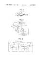
- FIG. 3 is a circuit diagram of a drive-and-sensor circuit 10 shown in FIG. 2;
- FIG. 4 is a block diagram of a control circuit 20 shown in FIG. 2;
- FIG. 5 is a timing chart used for the explanation of the mode of operation of the device for removing air bubbles.
- an ink-jet print head comprising an ink drop generator 1 having a piezoelectric crystal or the like 2 mounted on one wall of an ink chamber 4 and electrically connected through lead wires 3a and 3b to a synchronizing signal generator or drive circuit (not shown) and an orifice or nozzle 5.
- a periodic pressure variation applied to the ink in the ink chamber 4 by the piezoelectric crystal or the like 2 a continuous jet of ink issues through the nozzle 5 and breaks up into a stream of ink drops 6 which are deposited on a recording paper or the like (not shown).
- air bubble 7 is formed in the ink chamber 4 which is supplied with the ink through an ink supply line 8.
- the piezoelectric crystal or the like 2 is connected through wires 3a and 3b to a drive circuit 10 having a dual function of driving the piezoelectric crystal 2 and detecting whether or not an air bubble 7 is formed in the ink chamber 4. That is, as shown in FIG. 3, normally a pulse voltage with a predetermined pulse width is applied to a NAND gate 11 so that a transistor Tr 1 is turned off while a transistor Tr 2 is turned on to apply a high voltage pulse to the piezoelectric crystal or the like 2. In this case, in response to a control signal from a control circuit 20, a solenoid-controlled valve 70 communicates an ink tank or reservoir 30 with the ink drop generator 1 or ink chamber 4.
- the mechanical impedance of the ink chamber 4 looking from the piezoelectric crystal or the like 2 changes.
- the voltage across the piezoelectric crystal or the like 2 becomes in the form of a pulse voltage obtained by the superposition of the driving pulse voltage and voltages because of vibration of the printer.
- This superposed voltage is applied through a zener diode 12, which removes a voltage component corresponding to the driving pulse voltage, a potentiometer 13, a filter consisting of a capacitor 114 and a resistor 15 and a rectifier consisting of a diode 16 and a capacitor 17, to one input terminal of a voltage comparator 18.
- a reference voltage is applied to the other input terminal of the comparator 18.
- control circuit 20 In response to the detection of the air bubble 7; that is, in response to the high-level output a from the drive and sensor circuit 10, the control circuit 20 accomplishes a sequence of operations to be described below in order to remove the air bubble 7.
- a first monostable multi-vibrator 21 gives a high level signal b (See FIG. 5B) to a drive circuit 25 which in turns drives an electromagnetic pump 50 so as to draw the ink in a predetermined quantity from the ink chamber 4 in such a way that the level of the ink is maintained in the solenoid-controlled valve 70.
- the air bubble is in general in contact with the upper wall of the ink chamber 4 because of its buoyancy and is entrained by the ink flowing out of the ink chamber 4 when the ink is drawn in the manner described above.
- a second monostable multivibrator 22 gives a high-level signal c (See FIG. 5C) to a second driver 26 which in turn drives the valve 70 so that the ink reservoir 30 is cut off from the ink chamber 4 while a reservoir 40 containing an air-bubble expelling liquid is communication with the ink chamber.
- an electromagnetic pump 60 is driven so as to charge the air-bubble expelling liquid such as a primary alcohol into the ink chamber.
- the air-bubble expelling agent must have a low surface tension and a low viscosity so that it can completely fill the ink chamber 4 and entrain any air bubbles when discharged.
- a third monostable multivibrator 23 delivers a high-level output signal d for a predetermined time (See FIG. 5D).
- a fourth monostable multivibrator 24 delivers a high-level output signal e (See FIG. 5E) to a third driver 27 which in turns drives the control valve 70 so that the ink reservoir 30 is communicated again with the ink chamber while the air-bubble expelling agent reservoir 40 is cut off from the ink chamber 4.
- the air-bubble expelling agent is discharged through the nozzle 5 from the ink chamber 4 by driving the piezoelectric crystal or the like 2 or by the energy stored in the pump 50 or more particularly in a spring or the like when the pump 50 is driven in order to draw the ink from the ink chamber 4, this stored energy restoring the pump 50 to its initial position.
- the ink chamber 4 is filled again with the ink.
- the air bubbles formed and trapped in the ink chamber 4 can be completely removed by the device of the present invention which is very simple in construction yet highly reliable and dependable in operation and is inexpensive.
Abstract
A device for removing air bubbles formed and trapped in an ink chamber of an ink-jet print head, said device comprising a means for sensing the existance of air bubbles in the ink chamber, a means responsive to the output signal from the sensing means for replacing the ink in the ink chamber with an agent having a low surface tension, and a means for replacing the agent filled in the ink chamber with the ink.
Description
The present invention relates to generally an ink-jet printer and more particularly a device for removing air bubbles formed and trapped in an ink chamber of a print head thereof.
When air bubbles are formed and trapped in an ink chamber of a print head by any cause, the operation of issuing a continuous jet of ink and breaking it up into a stream of ink drops is considerably adversely affected. In the worst case, the ink drop generator cannot generate the ink drops at all. In order to overcome this problem, there have been devised and demonstrated various means, but all of them have been found unsatisfactory in practice. Once air bubbles are formed and trapped in the ink chamber, it is extremely difficult to remove them completely.
The primary object of the present invention is therefore to provide a device for readily and completely removing air bubbles from the ink chamber of an ink-jet print head.
According to one preferred embodiment of the present invention a means is provided which senses whether or not air bubbles are formed and trapped in the ink chamber of an ink drop generator. In response to the output signal from the sensor means, the ink in the ink chamber is completely drawn and replaced with an agent having a low surface tension. Since air bubbles will not mix with a liquid with a low surface tension, any air bubbles in the ink chamber can be completely removed. Thereafter the agent is replaced with the ink. These sequential operations can be automatically accomplished once manually started.
The above and other objects, effects, features and advantages of the present invention will become more apparent from the following description of a preferred embodiment thereof taken in conjunction with the accompanying drawings.
FIG. 1 is a longitudinal sectional view of an ink-jet print head to which is applied the present invention;
FIG. 2 is a block diagram of an ink supply system and a device or system for expelling air bubbles out of the ink chamber;
FIG. 3 is a circuit diagram of a drive-and-sensor circuit 10 shown in FIG. 2;
FIG. 4 is a block diagram of a control circuit 20 shown in FIG. 2; and
FIG. 5 is a timing chart used for the explanation of the mode of operation of the device for removing air bubbles.
In FIG. 1 is shown an ink-jet print head comprising an ink drop generator 1 having a piezoelectric crystal or the like 2 mounted on one wall of an ink chamber 4 and electrically connected through lead wires 3a and 3b to a synchronizing signal generator or drive circuit (not shown) and an orifice or nozzle 5. In response to a periodic pressure variation applied to the ink in the ink chamber 4 by the piezoelectric crystal or the like 2, a continuous jet of ink issues through the nozzle 5 and breaks up into a stream of ink drops 6 which are deposited on a recording paper or the like (not shown). Sometimes air bubble 7 is formed in the ink chamber 4 which is supplied with the ink through an ink supply line 8.
Referring to FIG. 2, the piezoelectric crystal or the like 2 is connected through wires 3a and 3b to a drive circuit 10 having a dual function of driving the piezoelectric crystal 2 and detecting whether or not an air bubble 7 is formed in the ink chamber 4. That is, as shown in FIG. 3, normally a pulse voltage with a predetermined pulse width is applied to a NAND gate 11 so that a transistor Tr1 is turned off while a transistor Tr2 is turned on to apply a high voltage pulse to the piezoelectric crystal or the like 2. In this case, in response to a control signal from a control circuit 20, a solenoid-controlled valve 70 communicates an ink tank or reservoir 30 with the ink drop generator 1 or ink chamber 4.
When an air bubble is formed in the ink chamber 4, the mechanical impedance of the ink chamber 4 looking from the piezoelectric crystal or the like 2 changes. As a result, the voltage across the piezoelectric crystal or the like 2 becomes in the form of a pulse voltage obtained by the superposition of the driving pulse voltage and voltages because of vibration of the printer. This superposed voltage is applied through a zener diode 12, which removes a voltage component corresponding to the driving pulse voltage, a potentiometer 13, a filter consisting of a capacitor 114 and a resistor 15 and a rectifier consisting of a diode 16 and a capacitor 17, to one input terminal of a voltage comparator 18. A reference voltage is applied to the other input terminal of the comparator 18. When the air bubble 7 exists in the ink chamber 4, then the output voltage of the comparator 18 rises to a high level as indicated at A in FIG. 5, whereby the presence of the air bubble 7 can be detected.
In response to the detection of the air bubble 7; that is, in response to the high-level output a from the drive and sensor circuit 10, the control circuit 20 accomplishes a sequence of operations to be described below in order to remove the air bubble 7.
Referring to FIG. 4 and FIG. 5, in response to the high-level voltage signal a from the drive and sensor circuit 10, a first monostable multi-vibrator 21 gives a high level signal b (See FIG. 5B) to a drive circuit 25 which in turns drives an electromagnetic pump 50 so as to draw the ink in a predetermined quantity from the ink chamber 4 in such a way that the level of the ink is maintained in the solenoid-controlled valve 70.
The air bubble is in general in contact with the upper wall of the ink chamber 4 because of its buoyancy and is entrained by the ink flowing out of the ink chamber 4 when the ink is drawn in the manner described above.
When the output signal from the first monostable multivibrator 21 falls to a low level, a second monostable multivibrator 22 gives a high-level signal c (See FIG. 5C) to a second driver 26 which in turn drives the valve 70 so that the ink reservoir 30 is cut off from the ink chamber 4 while a reservoir 40 containing an air-bubble expelling liquid is communication with the ink chamber. At the same time an electromagnetic pump 60 is driven so as to charge the air-bubble expelling liquid such as a primary alcohol into the ink chamber. The air-bubble expelling agent must have a low surface tension and a low viscosity so that it can completely fill the ink chamber 4 and entrain any air bubbles when discharged.
When the output signal of the second monostable multivibrator 23 falls to a low level, a third monostable multivibrator 23 delivers a high-level output signal d for a predetermined time (See FIG. 5D). After the output signal of the third multivibrator 23 falls to a low level, a fourth monostable multivibrator 24 delivers a high-level output signal e (See FIG. 5E) to a third driver 27 which in turns drives the control valve 70 so that the ink reservoir 30 is communicated again with the ink chamber while the air-bubble expelling agent reservoir 40 is cut off from the ink chamber 4. Thereafter the air-bubble expelling agent is discharged through the nozzle 5 from the ink chamber 4 by driving the piezoelectric crystal or the like 2 or by the energy stored in the pump 50 or more particularly in a spring or the like when the pump 50 is driven in order to draw the ink from the ink chamber 4, this stored energy restoring the pump 50 to its initial position. Thus the ink chamber 4 is filled again with the ink.
As described above, the air bubbles formed and trapped in the ink chamber 4 can be completely removed by the device of the present invention which is very simple in construction yet highly reliable and dependable in operation and is inexpensive.
Claims (1)
1. A device for removing air bubbles formed and trapped in an ink chamber of a print head of an ink-jet printer comprising
(a) a means for detecting the existence of air bubbles in said ink chamber,
(b) a means responsive to the output signal from said detection means for replacing the ink in the ink chamber with a liquid with a small surface tension and a low viscosity, and
(c) a means for replacing said liquid in said ink chamber with the ink.
Applications Claiming Priority (2)
| Application Number | Priority Date | Filing Date | Title |
|---|---|---|---|
| JP5802579A JPS55150373A (en) | 1979-05-14 | 1979-05-14 | Bubble remover for ink jet printer |
| JP54-58025 | 1979-05-14 |
Publications (1)
| Publication Number | Publication Date |
|---|---|
| US4293867A true US4293867A (en) | 1981-10-06 |
Family
ID=13072401
Family Applications (1)
| Application Number | Title | Priority Date | Filing Date |
|---|---|---|---|
| US06/147,277 Expired - Lifetime US4293867A (en) | 1979-05-14 | 1980-05-06 | Device for removing air bubbles formed and trapped in ink chamber of print head of ink-jet printer |
Country Status (2)
| Country | Link |
|---|---|
| US (1) | US4293867A (en) |
| JP (1) | JPS55150373A (en) |
Cited By (19)
| Publication number | Priority date | Publication date | Assignee | Title |
|---|---|---|---|---|
| US4362572A (en) * | 1981-06-25 | 1982-12-07 | Burroughs Corporation | Method and apparatus for cleaning ink jet printer heads |
| US4518974A (en) * | 1982-09-21 | 1985-05-21 | Ricoh Company, Ltd. | Ink jet air removal system |
| US4563688A (en) * | 1983-05-16 | 1986-01-07 | Eastman Kodak Company | Fluid jet printer and method of ultrasonic cleaning |
| US4739847A (en) * | 1984-02-24 | 1988-04-26 | Canon Kabushiki Kaisha | Ink jet printer |
| US5248999A (en) * | 1990-10-12 | 1993-09-28 | Seiko Epson Corporation | Ink jet printing apparatus having ink purging feature |
| US5500657A (en) * | 1991-11-11 | 1996-03-19 | Alps Electric Co., Ltd. | Air-bubble detection apparatus of ink jet recording head, and method and apparatus for restoring ink jet recording head |
| US5927547A (en) * | 1996-05-31 | 1999-07-27 | Packard Instrument Company | System for dispensing microvolume quantities of liquids |
| US6037955A (en) * | 1997-11-14 | 2000-03-14 | Eastman Kodak Company | Microfluidic image display |
| US6079808A (en) * | 1996-08-05 | 2000-06-27 | Seiko Epson Corporation | Ink jet recording apparatus |
| US6084605A (en) * | 1996-05-10 | 2000-07-04 | Oki Data Corporation | Ink jet printer |
| US6203759B1 (en) | 1996-05-31 | 2001-03-20 | Packard Instrument Company | Microvolume liquid handling system |
| US6217144B1 (en) * | 1996-06-25 | 2001-04-17 | Samsung Electronics Co., Ltd. | Method for checking nozzle contact status of recording head in ink jet recording apparatus |
| US6513898B1 (en) * | 1997-06-27 | 2003-02-04 | Stmicroelectronics S.R.L. | Integrated inkjet print head and manufacturing process thereof |
| US6521187B1 (en) | 1996-05-31 | 2003-02-18 | Packard Instrument Company | Dispensing liquid drops onto porous brittle substrates |
| US6537817B1 (en) | 1993-05-31 | 2003-03-25 | Packard Instrument Company | Piezoelectric-drop-on-demand technology |
| US20060012645A1 (en) * | 2004-07-16 | 2006-01-19 | Fuji Photo Film Co., Ltd. | Discharge head and image forming apparatus |
| US20060170744A1 (en) * | 2005-02-03 | 2006-08-03 | Oce-Technologies B.V. | Printing method for use in an inkjet printer and an inkjet printer which has been modified for the printing method |
| US20060244777A1 (en) * | 1999-10-12 | 2006-11-02 | Robert Paasch | Print head apparatus with malfunction detector |
| US20070292162A1 (en) * | 2006-06-15 | 2007-12-20 | Keren Regev | Systems, methods, and compositions for reducing ink foam |
Citations (4)
| Publication number | Priority date | Publication date | Assignee | Title |
|---|---|---|---|---|
| US4050078A (en) * | 1974-12-09 | 1977-09-20 | Ricoh Company, Ltd. | Automatic nozzle cleaning system for ink ejection printer |
| US4123761A (en) * | 1976-06-07 | 1978-10-31 | Konishiroku Photo Industry Co., Ltd. | Method of purging ink passages of an ink jet recording device |
| US4148041A (en) * | 1977-02-04 | 1979-04-03 | Siemens Aktiengesellschaft | Method and apparatus for purging air from jet ink writing systems |
| US4183029A (en) * | 1977-07-28 | 1980-01-08 | Ricoh Company, Ltd. | Ink filter clogging sensor and indicator |
Family Cites Families (1)
| Publication number | Priority date | Publication date | Assignee | Title |
|---|---|---|---|---|
| JPS51117530A (en) * | 1975-04-08 | 1976-10-15 | Ricoh Co Ltd | Ink drop jet device |
-
1979
- 1979-05-14 JP JP5802579A patent/JPS55150373A/en active Pending
-
1980
- 1980-05-06 US US06/147,277 patent/US4293867A/en not_active Expired - Lifetime
Patent Citations (4)
| Publication number | Priority date | Publication date | Assignee | Title |
|---|---|---|---|---|
| US4050078A (en) * | 1974-12-09 | 1977-09-20 | Ricoh Company, Ltd. | Automatic nozzle cleaning system for ink ejection printer |
| US4123761A (en) * | 1976-06-07 | 1978-10-31 | Konishiroku Photo Industry Co., Ltd. | Method of purging ink passages of an ink jet recording device |
| US4148041A (en) * | 1977-02-04 | 1979-04-03 | Siemens Aktiengesellschaft | Method and apparatus for purging air from jet ink writing systems |
| US4183029A (en) * | 1977-07-28 | 1980-01-08 | Ricoh Company, Ltd. | Ink filter clogging sensor and indicator |
Cited By (28)
| Publication number | Priority date | Publication date | Assignee | Title |
|---|---|---|---|---|
| US4362572A (en) * | 1981-06-25 | 1982-12-07 | Burroughs Corporation | Method and apparatus for cleaning ink jet printer heads |
| US4518974A (en) * | 1982-09-21 | 1985-05-21 | Ricoh Company, Ltd. | Ink jet air removal system |
| US4563688A (en) * | 1983-05-16 | 1986-01-07 | Eastman Kodak Company | Fluid jet printer and method of ultrasonic cleaning |
| US4739847A (en) * | 1984-02-24 | 1988-04-26 | Canon Kabushiki Kaisha | Ink jet printer |
| US5248999A (en) * | 1990-10-12 | 1993-09-28 | Seiko Epson Corporation | Ink jet printing apparatus having ink purging feature |
| US5500657A (en) * | 1991-11-11 | 1996-03-19 | Alps Electric Co., Ltd. | Air-bubble detection apparatus of ink jet recording head, and method and apparatus for restoring ink jet recording head |
| US6537817B1 (en) | 1993-05-31 | 2003-03-25 | Packard Instrument Company | Piezoelectric-drop-on-demand technology |
| US6084605A (en) * | 1996-05-10 | 2000-07-04 | Oki Data Corporation | Ink jet printer |
| US6079283A (en) * | 1996-05-31 | 2000-06-27 | Packard Instruments Comapny | Method for aspirating sample liquid into a dispenser tip and thereafter ejecting droplets therethrough |
| US6083762A (en) * | 1996-05-31 | 2000-07-04 | Packard Instruments Company | Microvolume liquid handling system |
| US6592825B2 (en) | 1996-05-31 | 2003-07-15 | Packard Instrument Company, Inc. | Microvolume liquid handling system |
| US6112605A (en) * | 1996-05-31 | 2000-09-05 | Packard Instrument Company | Method for dispensing and determining a microvolume of sample liquid |
| US6203759B1 (en) | 1996-05-31 | 2001-03-20 | Packard Instrument Company | Microvolume liquid handling system |
| US6422431B2 (en) | 1996-05-31 | 2002-07-23 | Packard Instrument Company, Inc. | Microvolume liquid handling system |
| US6521187B1 (en) | 1996-05-31 | 2003-02-18 | Packard Instrument Company | Dispensing liquid drops onto porous brittle substrates |
| US5927547A (en) * | 1996-05-31 | 1999-07-27 | Packard Instrument Company | System for dispensing microvolume quantities of liquids |
| US6217144B1 (en) * | 1996-06-25 | 2001-04-17 | Samsung Electronics Co., Ltd. | Method for checking nozzle contact status of recording head in ink jet recording apparatus |
| US6079808A (en) * | 1996-08-05 | 2000-06-27 | Seiko Epson Corporation | Ink jet recording apparatus |
| US6513898B1 (en) * | 1997-06-27 | 2003-02-04 | Stmicroelectronics S.R.L. | Integrated inkjet print head and manufacturing process thereof |
| US6037955A (en) * | 1997-11-14 | 2000-03-14 | Eastman Kodak Company | Microfluidic image display |
| US20060244777A1 (en) * | 1999-10-12 | 2006-11-02 | Robert Paasch | Print head apparatus with malfunction detector |
| US7249818B1 (en) * | 1999-10-12 | 2007-07-31 | Hewlett-Packard Development Company, L.P. | Print head apparatus with malfunction detector |
| US7717531B2 (en) | 1999-10-12 | 2010-05-18 | Hewlett-Packard Development Company, L.P. | Print head apparatus with malfunction detector |
| US20060012645A1 (en) * | 2004-07-16 | 2006-01-19 | Fuji Photo Film Co., Ltd. | Discharge head and image forming apparatus |
| US7527363B2 (en) * | 2004-07-16 | 2009-05-05 | Fujifilm Corporation | Discharge head of image forming apparatus with piezoelectric body for generating and sensing pressure |
| US20060170744A1 (en) * | 2005-02-03 | 2006-08-03 | Oce-Technologies B.V. | Printing method for use in an inkjet printer and an inkjet printer which has been modified for the printing method |
| US7488062B2 (en) * | 2005-02-03 | 2009-02-10 | Oce-Technologies B.V. | Printing method for use in an inkjet printer and an inkjet printer which has been modified for the printing method |
| US20070292162A1 (en) * | 2006-06-15 | 2007-12-20 | Keren Regev | Systems, methods, and compositions for reducing ink foam |
Also Published As
| Publication number | Publication date |
|---|---|
| JPS55150373A (en) | 1980-11-22 |
Similar Documents
| Publication | Publication Date | Title |
|---|---|---|
| US4293867A (en) | Device for removing air bubbles formed and trapped in ink chamber of print head of ink-jet printer | |
| US5500657A (en) | Air-bubble detection apparatus of ink jet recording head, and method and apparatus for restoring ink jet recording head | |
| US4498088A (en) | Ink jet air bubble detection | |
| US4636814A (en) | Printing apparatus | |
| EP0221703B1 (en) | Ink jet print head | |
| US4466005A (en) | Air bubble removing system in a printer head of an ink jet system printer of the ink on demand type | |
| EP1413441B1 (en) | Ink jet printer and method of controlling it | |
| US6908174B2 (en) | Ink jet recording apparatus | |
| US4518974A (en) | Ink jet air removal system | |
| EP0440110A1 (en) | Ink near-end detecting device | |
| JPS6046256A (en) | Liquid jet recorder | |
| EP0045382A1 (en) | A method of operating an ink jet printer and a drop-on-demand ink jet printer | |
| US8075115B2 (en) | Mountable apparatus and board having an installation status notifier | |
| US5255019A (en) | Ink near-end detecting device | |
| US4980699A (en) | Liquid injection recording method for accurately producing an image regardless of ambient temperature | |
| JP2000117993A5 (en) | ||
| JPS6024954A (en) | Detection of residual ink amount in ink jet printer | |
| US5255021A (en) | Ink-jet printer having an ink jet print head end of life detection circuit | |
| JPH0639162B2 (en) | Ink volume abnormality alarm output method | |
| JPH0519467B2 (en) | ||
| JPS592620B2 (en) | ink ejection device | |
| WO2009113727A1 (en) | Liquid container, baseboard, and method of changing liquid information | |
| JPH1044449A (en) | Ink jet recorder | |
| JP2616232B2 (en) | Ink tank for inkjet recording device | |
| JPS5851160A (en) | Ink jet recorder |
Legal Events
| Date | Code | Title | Description |
|---|---|---|---|
| STCF | Information on status: patent grant |
Free format text: PATENTED CASE |