US4579709A - Method for molding hinged article - Google Patents
Method for molding hinged article Download PDFInfo
- Publication number
- US4579709A US4579709A US06/554,823 US55482383A US4579709A US 4579709 A US4579709 A US 4579709A US 55482383 A US55482383 A US 55482383A US 4579709 A US4579709 A US 4579709A
- Authority
- US
- United States
- Prior art keywords
- pin
- mold
- cavities
- hinge
- leaf
- Prior art date
- Legal status (The legal status is an assumption and is not a legal conclusion. Google has not performed a legal analysis and makes no representation as to the accuracy of the status listed.)
- Expired - Fee Related
Links
Images


Classifications
-
- B—PERFORMING OPERATIONS; TRANSPORTING
- B29—WORKING OF PLASTICS; WORKING OF SUBSTANCES IN A PLASTIC STATE IN GENERAL
- B29C—SHAPING OR JOINING OF PLASTICS; SHAPING OF MATERIAL IN A PLASTIC STATE, NOT OTHERWISE PROVIDED FOR; AFTER-TREATMENT OF THE SHAPED PRODUCTS, e.g. REPAIRING
- B29C45/00—Injection moulding, i.e. forcing the required volume of moulding material through a nozzle into a closed mould; Apparatus therefor
- B29C45/0017—Injection moulding, i.e. forcing the required volume of moulding material through a nozzle into a closed mould; Apparatus therefor moulding interconnected elements which are movable with respect to one another, e.g. chains or hinges
- B29C2045/0024—Injection moulding, i.e. forcing the required volume of moulding material through a nozzle into a closed mould; Apparatus therefor moulding interconnected elements which are movable with respect to one another, e.g. chains or hinges using a mould core with a blind hole wherein the hinge shaft is moulded
Definitions
- the present invention relates to injection molding and in particular to an improved mold and method for molding hinged articles.
- the hinged sections are individually formed with loops or knuckles provided at an edge which cooperate with a separate pin in defining the hinge.
- Small plastic box components are sometimes formed with spaced spherical balls at an edge. When a similar ball on a mating component is snapped between the spaced balls a hinge is defined.
- one hinged member is molded with a hook at an edge and the other is molded with an eye. The engagement of the hook and eye define yet another type of hinge.
- a further object is to provide such a mold and molding technique wherein the hinged components may be formed, within limits, of different plastic materials.
- a still further object is to provide such a mold and molding technique which may be used with conventional injection molding equipment.
- a conventional injection molding apparatus with a pair of mold cavities for forming the leaves of the hinged article.
- the cavities include a pair of interdigitated sections of the leaves in which the desired hinge is formed.
- Reciprocating pin assemblies each comprising an inner pin secured in an outer hollow pin are positioned within the mold in line with the interdigitated sections and extending through the cavity section of the first leaf to the cavity section of the second leaf.
- the inner pin cross section is dissimilar from that of the outer pin so as to define an air passageway between the inner and outer pins.
- FIG. 1 is a perspective view of a sample integrally formed hinged article in accordance with the present invention
- FIG. 2 is a sectional view taken along reference lines 2--2 of FIG. 1 in the direction indicated by the arrows;
- FIG. 3 is a sectional view taken along reference lines 3--3 of FIG. 2 in the direction indicated by the arrows;
- FIG. 4 is a sectional view taken along reference lines 4--4 in the direction indicated by the arrows;
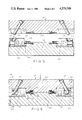
- FIG. 5 is a side sectional view of the top and bottom portions of the mold used to form the article of FIG. 1 in accordance with the present invention with the mold shown in an open condition;
- FIG. 6 is a view similar to FIG. 5 with the mold shown in the closed position;
- FIG. 7 is a plan view of the top mold half
- FIG. 8 is a top plan view of the bottom mold half
- FIG. 9 is a sectional view taken of the mold in a partially open condition depicting the flow of plastic melt through the pin assembly
- FIG. 10 is a fragmentary exploded perspective view of the mold and mold pin assembly
- FIG. 11 is an enlarged sectional view of the mold pin assembly.
- FIG. 12 is an exploded view of the mold pin assembly.
- FIG. 1 an injection molded hinged article 10 produced in accordance with the present invention is depicted.
- the article 10 includes a pair of leaves 12, 14 connected to each other at their edges by a pair of hinges 16, 18.
- leaf 14 could easily have been a box and leaf 12 the cover for the box or that leaves 12, 14 could be any two hinged components.
- leaf is meant to denote a component of a hinged article regardless of what that article may actually be.
- each of the hinges 16, 18 is formed of two parts, a male part 20, 22 connected to and integral with leaf 14 and a female part 24, 26 connected to and integral with leaf 12.
- a stud 28 on male part 20 penetrates a bore 30 through female part 24 and a corresponding stud 32 on male part 22 penetrates a bore 34 through female part 26.
- the studs 28, 32 are directed away from each other (as shown best in FIG. 2) thereby preventing the leaves 12, 14 from separating.
- a slight gap 36 between the stud and the wall of female part 24 permits the hinge leaves 12, 14 to freely rotate with respect to each other.
- a series of countersunk screw holes 38 extending through the leaves permits the hinge to be fastened in a conventional manner to a door post and door.
- a rod 40 (shown in phantom in FIG. 1) may be integrally molded with leaf 14 aligned with studs 28 and 32 to give the appearance of a conventional hinge pin extending between hinges 16 and 18.
- the hinged article 10 is injection molded in one piece, already assembled in a two piece mold 42.
- mold 42 includes a pair of cavities 48, 50 for pin assemblies 52, 54.
- Mold 42 comprises a top portion 56 shown in FIGS. 8 and 9 and bottom portion 58 shown in FIG. 7.
- cavity 48 is defined by mating recesses 60, 62 in top and bottom mold portions 56, 58 and cavity 50 is defined by similarly mating recesses 64, 66.
- a rod 68 extends at a downwardly and outwardly directed angle through recess 60 of upper mold portion 56 extending beyond the bottom face of the upper mold half.
- a similar rod 70 extends through recess 64.
- the rods 68 and 70 serve to drive the pin assemblies outwardly and inwardly as the mold is opened and closed.
- Pin assemblies 52 and 54 are identical as are the cooperating portions of the mold. Accordingly, the following description is directed at pin assembly 54 as representative of both.
- pin assembly 54 comprises a generally rectangular housing 72 through which a generally horizontal bore 74 extends.
- a diagonal bore 76 extends through the top surface 78 of the housing and communicates with the horizontal bore 74.
- the diameter and angle of bore 76 are such as to receive rod 70. This is shown in FIG. 10.
- a pair of glides 80, 82 extend outwardly from the bottom of housing 72.
- the glides 80, 82 are captured in slots 84, 86 at the bottom of the lower mold pin assembly recess 66.
- pin assembly 54 moves outwardly (i.e.
- Pin assembly 54 includes an outer hollow pin 88 extending from the forward surface 90 of housing 72. Pin 88 is coaxial with horizontal bore 74. An out-of-round inner pin 92 is positioned within the extension of bore 74 of that extends through the outer pin 88. The forward edge 96 of inner pin 92 is set back from the forward edge 94 of the outer pin by a distance that will eventually define the height of stud 28. To this end, when pin assembly 54 is in its inner-most position (as shown in FIG. 6) the forward edge 98 of outer pin 88 communicates with a mold recess 100 that defines the cavity for the male hinge part 20. The forward edge of the inner pin is spaced slightly outward of a mold recess 102 that defines the cavity for the female hinge part 24.
- the pin assembly glides 80, 82 are positioned in slots 84, 86 and the drive rod 70 is aligned with bore 76.
- the mold is then closed thereby causing the drive rod 70 to move pin assembly 54 to its innermost position.
- Plastic melt is then injected into the mold cavities 44, 46 though injectors 104, 106 and gates 108, 110. It should be noted that the same plastic may be injected into cavities 44, 46 or a different plastic may be injected into each. This may be extremely useful as, for example where the article being molded is a box and it is desireable to have one color plastic for the box body and another color for the lid.
- plastic melt flows into the cavities 44, 46 as well as the cavities 100, 102.
- plastic melt flows into the interior of outer pin 88 to the front surface of the inner pin. Because the cross section of the inner pin is out-of-round, a series of air bleed passageways are defined along the length of the inner pin eventually communicating with the opening at the rear of the housing as defined by bore 74. Thus, as plastic melt flows into the lumen of pin 88 air is evacuated from the lumen through the rear of the housing.
- the pin assemblies move outwardly under the operation of drive rods 68, 70 until the forward edge of outer pin 88 clears the female hinge portion cavity 102.
- the thus molded article may then be removed from the cavity and the two components of the molded hinge assembly will already be hinged together.
- the mold may then be reclosed to receive another charge of melt and the process can then be repeated.
- the molded article is a hinge, such as shown in FIG. 1, the countersunk screw holes 38 may be formed during the molding process by providing pins 114 in the bottom portion 58 of the mold as shown in FIG. 7.
Abstract
Description
Claims (5)
Priority Applications (1)
| Application Number | Priority Date | Filing Date | Title |
|---|---|---|---|
| US06/554,823 US4579709A (en) | 1983-11-23 | 1983-11-23 | Method for molding hinged article |
Applications Claiming Priority (1)
| Application Number | Priority Date | Filing Date | Title |
|---|---|---|---|
| US06/554,823 US4579709A (en) | 1983-11-23 | 1983-11-23 | Method for molding hinged article |
Publications (1)
| Publication Number | Publication Date |
|---|---|
| US4579709A true US4579709A (en) | 1986-04-01 |
Family
ID=24214843
Family Applications (1)
| Application Number | Title | Priority Date | Filing Date |
|---|---|---|---|
| US06/554,823 Expired - Fee Related US4579709A (en) | 1983-11-23 | 1983-11-23 | Method for molding hinged article |
Country Status (1)
| Country | Link |
|---|---|
| US (1) | US4579709A (en) |
Cited By (23)
| Publication number | Priority date | Publication date | Assignee | Title |
|---|---|---|---|---|
| JPS5928330U (en) * | 1982-08-12 | 1984-02-22 | 日本ノーション工業株式会社 | belt adjuster |
| JPS6124520U (en) * | 1985-05-11 | 1986-02-13 | 日本ノ−シヨン工業株式会社 | Synthetic resin eggplant ring |
| US4680837A (en) * | 1985-12-23 | 1987-07-21 | Leon Rubinstein | Plastic swivel connector and mold therefor |
| US4699747A (en) * | 1984-03-23 | 1987-10-13 | Itw Fastex Italia S.P.A. | Method of molding a plastic buckle with floating center bar |
| FR2618839A1 (en) * | 1987-07-30 | 1989-02-03 | United Carr Gmbh Trw | ARTICULATED CONNECTION BETWEEN TWO PIECES OF PLASTIC MATERIAL IN PARTICULAR OF THE HINGE TYPE |
| EP0330607A1 (en) * | 1988-02-24 | 1989-08-30 | Cendres Et Metaux S.A. | Method of producing a detachable connection between a removable dental prosthesis and a fixed artificial tooth, and aid for carrying out this method |
| FR2752541A1 (en) * | 1996-08-23 | 1998-02-27 | Qualipac Sa | Injection moulded container body with hinged lid |
| DE19725642A1 (en) * | 1997-06-18 | 1998-12-24 | Bosch Gmbh Robert | Process for producing a composite from two plastic parts |
| FR2768646A1 (en) * | 1997-09-19 | 1999-03-26 | Armoricaine Mecano Plastique S | Making a box comprising two hinged shells, entirely in plastic |
| NL1007859C2 (en) * | 1997-12-19 | 1999-06-22 | Den Brink B V Van | Injection mold and method for manufacturing a bucket provided with a handle, as well as a bucket manufactured with said injection mold. |
| WO2001089795A1 (en) * | 2000-05-26 | 2001-11-29 | Sandro Galli | Improved hinge construction and the mold for making it |
| US6667002B1 (en) * | 1998-01-08 | 2003-12-23 | Illinois Tool Works Inc. | Method for molding a swivel hinge |
| US20050103797A1 (en) * | 2003-11-13 | 2005-05-19 | Monoflo International, Inc. | Plastic container including plastic hinge assembly |
| US20050270476A1 (en) * | 2004-06-02 | 2005-12-08 | Bacou-Dalloz Eye & Face Protection | Flexible frame assembly for eyeglasses |
| US20080134466A1 (en) * | 2006-12-11 | 2008-06-12 | Trw Automotive U.S. Llc | Integrally molded hinge assembly and method of manufacturing the same |
| US20090174112A1 (en) * | 2006-06-20 | 2009-07-09 | Broadhead Douglas G | Method and system for molding integral joint |
| US20130015605A1 (en) * | 2009-11-27 | 2013-01-17 | Meus S.R.L. | Method for the Production of Bodies in Plastic Material Comprising at Least Two Portions Hinged to Each Other by a Single Rotation Pin |
| US20130209733A1 (en) * | 2010-10-29 | 2013-08-15 | Konica Minolta, Inc. | Microchip, molding die for microchip, and manufacturing apparatus for manufacturing microchip |
| US20140001674A1 (en) * | 2012-06-28 | 2014-01-02 | Lee-Yeh Lu | Manufacturing method for a hinge |
| DE102005028849B4 (en) | 2005-06-22 | 2021-11-18 | Kostal Automobil Elektrik Gmbh & Co. Kg | Arrangement with at least two parts that are adapted to one another in terms of their shape and are linearly movable with respect to one another |
| US11338524B1 (en) * | 2018-10-26 | 2022-05-24 | Afl Telecommunications Llc | Method of forming a foldable or collapsible plastic and/or composite utility enclosure |
| US11349281B1 (en) | 2018-10-26 | 2022-05-31 | Afl Telecommunications Llc | Foldable and/or collapsible plastic/composite utility enclosure |
| US11374386B2 (en) | 2018-10-26 | 2022-06-28 | Afl Telecommunications Llc | Foldable and/or collapsible plastic/composite utility enclosure |
Citations (1)
| Publication number | Priority date | Publication date | Assignee | Title |
|---|---|---|---|---|
| US3443005A (en) * | 1965-10-24 | 1969-05-06 | Arthur R Braun | Plural part molding |
-
1983
- 1983-11-23 US US06/554,823 patent/US4579709A/en not_active Expired - Fee Related
Patent Citations (1)
| Publication number | Priority date | Publication date | Assignee | Title |
|---|---|---|---|---|
| US3443005A (en) * | 1965-10-24 | 1969-05-06 | Arthur R Braun | Plural part molding |
Cited By (44)
| Publication number | Priority date | Publication date | Assignee | Title |
|---|---|---|---|---|
| JPS5928330U (en) * | 1982-08-12 | 1984-02-22 | 日本ノーション工業株式会社 | belt adjuster |
| JPH0131064Y2 (en) * | 1982-08-12 | 1989-09-22 | ||
| US4699747A (en) * | 1984-03-23 | 1987-10-13 | Itw Fastex Italia S.P.A. | Method of molding a plastic buckle with floating center bar |
| JPS6124520U (en) * | 1985-05-11 | 1986-02-13 | 日本ノ−シヨン工業株式会社 | Synthetic resin eggplant ring |
| JPS634813Y2 (en) * | 1985-05-11 | 1988-02-08 | ||
| US4680837A (en) * | 1985-12-23 | 1987-07-21 | Leon Rubinstein | Plastic swivel connector and mold therefor |
| FR2618839A1 (en) * | 1987-07-30 | 1989-02-03 | United Carr Gmbh Trw | ARTICULATED CONNECTION BETWEEN TWO PIECES OF PLASTIC MATERIAL IN PARTICULAR OF THE HINGE TYPE |
| EP0330607A1 (en) * | 1988-02-24 | 1989-08-30 | Cendres Et Metaux S.A. | Method of producing a detachable connection between a removable dental prosthesis and a fixed artificial tooth, and aid for carrying out this method |
| FR2752541A1 (en) * | 1996-08-23 | 1998-02-27 | Qualipac Sa | Injection moulded container body with hinged lid |
| DE19725642A1 (en) * | 1997-06-18 | 1998-12-24 | Bosch Gmbh Robert | Process for producing a composite from two plastic parts |
| FR2768646A1 (en) * | 1997-09-19 | 1999-03-26 | Armoricaine Mecano Plastique S | Making a box comprising two hinged shells, entirely in plastic |
| NL1007859C2 (en) * | 1997-12-19 | 1999-06-22 | Den Brink B V Van | Injection mold and method for manufacturing a bucket provided with a handle, as well as a bucket manufactured with said injection mold. |
| EP0924044A1 (en) * | 1997-12-19 | 1999-06-23 | van den Brink B.V. | Injection mold, method for manufacturing a bucket provided with a handle, and bucket manufactured with such injection mold |
| US6667002B1 (en) * | 1998-01-08 | 2003-12-23 | Illinois Tool Works Inc. | Method for molding a swivel hinge |
| WO2001089795A1 (en) * | 2000-05-26 | 2001-11-29 | Sandro Galli | Improved hinge construction and the mold for making it |
| US20050103797A1 (en) * | 2003-11-13 | 2005-05-19 | Monoflo International, Inc. | Plastic container including plastic hinge assembly |
| US20060279694A1 (en) * | 2004-06-02 | 2006-12-14 | Raymond Curci | Temple bar with ball and socket hinge |
| US7175270B2 (en) | 2004-06-02 | 2007-02-13 | Bacou-Dalloz Eye & Face Protection, Inc. | Flexible frame assembly for eyeglasses |
| US20050270475A1 (en) * | 2004-06-02 | 2005-12-08 | Bacou-Dalloz Eye & Face Protection | Nose pad assembly for eyeglasses |
| US20050270479A1 (en) * | 2004-06-02 | 2005-12-08 | Bacou-Dalloz Eye & Face Protection | Floating lens brow bar attachment for eyeglasses |
| US20050270478A1 (en) * | 2004-06-02 | 2005-12-08 | Bacou-Dalloz Eye & Face Protection | Temple bar assembly for eyeglasses |
| US20050270480A1 (en) * | 2004-06-02 | 2005-12-08 | Bacou-Dalloz Eye & Face Protection | Temple bar with ball and socket hinge and method of making same |
| US20050270476A1 (en) * | 2004-06-02 | 2005-12-08 | Bacou-Dalloz Eye & Face Protection | Flexible frame assembly for eyeglasses |
| US7758789B2 (en) | 2004-06-02 | 2010-07-20 | Sperian Eye & Face Protection, Inc. | Temple bar assembly for eyeglasses |
| US7210777B2 (en) | 2004-06-02 | 2007-05-01 | Bacou-Dalloz Eye & Face Protection, Inc. | Floating lens brow bar attachment for eyeglasses |
| US7237892B2 (en) | 2004-06-02 | 2007-07-03 | Bacou-Dalloz Eye & Face Protection, Inc. | Temple bar with ball and socket hinge and method of making same |
| US7246901B2 (en) | 2004-06-02 | 2007-07-24 | Bacou - Dalloz Eye & Face Protection, Inc. | Adjustable length upper frame member for eyeglasses |
| US20080042317A1 (en) * | 2004-06-02 | 2008-02-21 | Bacou-Dalloz Eye And Face Protection, Inc. | Temple bar assembly for eyeglasses |
| US20050270477A1 (en) * | 2004-06-02 | 2005-12-08 | Bacou-Dalloz Eye & Face Protection | Adjustable length upper frame member for eyeglasses |
| DE102005028849B4 (en) | 2005-06-22 | 2021-11-18 | Kostal Automobil Elektrik Gmbh & Co. Kg | Arrangement with at least two parts that are adapted to one another in terms of their shape and are linearly movable with respect to one another |
| US20090174112A1 (en) * | 2006-06-20 | 2009-07-09 | Broadhead Douglas G | Method and system for molding integral joint |
| US8092738B2 (en) * | 2006-06-20 | 2012-01-10 | Magna Closures Inc. | Method for molding an integral joint |
| US20080134466A1 (en) * | 2006-12-11 | 2008-06-12 | Trw Automotive U.S. Llc | Integrally molded hinge assembly and method of manufacturing the same |
| US20130015605A1 (en) * | 2009-11-27 | 2013-01-17 | Meus S.R.L. | Method for the Production of Bodies in Plastic Material Comprising at Least Two Portions Hinged to Each Other by a Single Rotation Pin |
| US8815136B2 (en) * | 2009-11-27 | 2014-08-26 | Meus S.R.L. | Method for the production of bodies in plastic material comprising at least two portions hinged to each other by a single rotation pin |
| US20130209733A1 (en) * | 2010-10-29 | 2013-08-15 | Konica Minolta, Inc. | Microchip, molding die for microchip, and manufacturing apparatus for manufacturing microchip |
| US9238322B2 (en) * | 2010-10-29 | 2016-01-19 | Wako Pure Chemical Industries, Ltd. | Microchip, molding die for microchip, and manufacturing apparatus for manufacturing microchip |
| US20140001674A1 (en) * | 2012-06-28 | 2014-01-02 | Lee-Yeh Lu | Manufacturing method for a hinge |
| US11338524B1 (en) * | 2018-10-26 | 2022-05-24 | Afl Telecommunications Llc | Method of forming a foldable or collapsible plastic and/or composite utility enclosure |
| US11349281B1 (en) | 2018-10-26 | 2022-05-31 | Afl Telecommunications Llc | Foldable and/or collapsible plastic/composite utility enclosure |
| US11374386B2 (en) | 2018-10-26 | 2022-06-28 | Afl Telecommunications Llc | Foldable and/or collapsible plastic/composite utility enclosure |
| US11670918B2 (en) | 2018-10-26 | 2023-06-06 | Afl Telecommunications Llc | Foldable and/or collapsible plastic/composite utility enclosure |
| US11670917B2 (en) | 2018-10-26 | 2023-06-06 | Afl Telecommunications Llc | Foldable and/or collapsible plastic/composite utility enclosure |
| US11766834B2 (en) | 2018-10-26 | 2023-09-26 | Afl Telecommunications Llc | Method of forming a foldable or collapsible plastic/composite utility enclosure |
Similar Documents
| Publication | Publication Date | Title |
|---|---|---|
| US4579709A (en) | Method for molding hinged article | |
| DE19744107A1 (en) | Injection of resin to produce a moulding with a thick section on one side and a high quality surface finish | |
| DE69824526T2 (en) | Separable lower end stop for concealed zips | |
| US8857351B2 (en) | Modular support assembly with fortifying flange | |
| CN216373194U (en) | Injection mold convenient to get material | |
| US5350555A (en) | Process for two stage injection molding of air-conditioning blow-out port device | |
| DE2501291A1 (en) | Injection moulding of hollow bodies - using three-part injection mould | |
| FR2511273A1 (en) | MOLD AND METHOD FOR THE MANUFACTURE BY MOLDING AN OBJECT ARTICULATED IN PARTICULAR FROM A BRACELET OR AN ARTICULATED COVER PACK | |
| US6453699B1 (en) | Hollow jewelry ring design | |
| US11426669B2 (en) | Method of manufacturing a model car body | |
| DE3908479A1 (en) | HINGE AND METHOD FOR THE PRODUCTION THEREOF | |
| DE10250765B4 (en) | Method for molding a molded part with flap and molded part with flap | |
| US7637123B2 (en) | Hollow metal jewelry ring | |
| EP0919060B1 (en) | Hinged case | |
| US5102607A (en) | Method for molding products with undercut regions | |
| US2218091A (en) | Die casting die | |
| DE3739498A1 (en) | STORAGE CONTAINER FOR A STACK OF SHEETS | |
| CN217704452U (en) | Assembled children wardrobe panel shape structure forming die that preapres for an unfavorable turn of events | |
| DE102005056630A1 (en) | Producing a shaped product comprises pressing out a flat part of the product and compressing the flat part with another part that completes the product | |
| CN218557854U (en) | Double-slider double-inclined top forming die | |
| CN216914710U (en) | Mould benevolence subassembly and pull-out mechanism that plastic mould components of a whole that can function independently set up | |
| DE19932278A1 (en) | Gas-assisted pressure injection molding for attachment inside motor vehicle includes hollow section with curved front wall conforming with class A finish standards and avoiding sagging | |
| US20140050906A1 (en) | Injection molded panel, a mold and a method for its manufacture | |
| CN214324078U (en) | Front mould inclined ejection mould | |
| CN216182407U (en) | Sliding type long core-pulling injection mold |
Legal Events
| Date | Code | Title | Description |
|---|---|---|---|
| AS | Assignment |
Owner name: BLUMBERG H ARTHUR 21 HILLTOP CT WOODBURY NY 11797 Free format text: ASSIGN TO EACH ASSIGNEE, 1/3 INTEREST.;ASSIGNOR:FERRERI, NICHOLAS;REEL/FRAME:004202/0122 Effective date: 19831104 Owner name: SLAVINSKY DANIEL C 3 3RD ST HOLBROOK NY Free format text: ASSIGN TO EACH ASSIGNEE, 1/3 INTEREST.;ASSIGNOR:FERRERI, NICHOLAS;REEL/FRAME:004202/0122 Effective date: 19831104 |
|
| REMI | Maintenance fee reminder mailed | ||
| LAPS | Lapse for failure to pay maintenance fees | ||
| STCH | Information on status: patent discontinuation |
Free format text: PATENT EXPIRED DUE TO NONPAYMENT OF MAINTENANCE FEES UNDER 37 CFR 1.362 |
|
| FP | Lapsed due to failure to pay maintenance fee |
Effective date: 19900401 |
|
| LAPS | Lapse for failure to pay maintenance fees |
Free format text: PATENT EXPIRED FOR FAILURE TO PAY MAINTENANCE FEES (ORIGINAL EVENT CODE: EXP.); ENTITY STATUS OF PATENT OWNER: SMALL ENTITY |