US5452124A - Unidirectional amplification for bi-directional transmission using wavelength-division multiplexing - Google Patents
Unidirectional amplification for bi-directional transmission using wavelength-division multiplexing Download PDFInfo
- Publication number
- US5452124A US5452124A US08/206,423 US20642394A US5452124A US 5452124 A US5452124 A US 5452124A US 20642394 A US20642394 A US 20642394A US 5452124 A US5452124 A US 5452124A
- Authority
- US
- United States
- Prior art keywords
- optical
- fiber
- amplifier
- port
- wavelength
- Prior art date
- Legal status (The legal status is an assumption and is not a legal conclusion. Google has not performed a legal analysis and makes no representation as to the accuracy of the status listed.)
- Expired - Lifetime
Links
Images


Classifications
-
- G—PHYSICS
- G02—OPTICS
- G02B—OPTICAL ELEMENTS, SYSTEMS OR APPARATUS
- G02B6/00—Light guides; Structural details of arrangements comprising light guides and other optical elements, e.g. couplings
- G02B6/24—Coupling light guides
- G02B6/26—Optical coupling means
- G02B6/28—Optical coupling means having data bus means, i.e. plural waveguides interconnected and providing an inherently bidirectional system by mixing and splitting signals
- G02B6/293—Optical coupling means having data bus means, i.e. plural waveguides interconnected and providing an inherently bidirectional system by mixing and splitting signals with wavelength selective means
- G02B6/29379—Optical coupling means having data bus means, i.e. plural waveguides interconnected and providing an inherently bidirectional system by mixing and splitting signals with wavelength selective means characterised by the function or use of the complete device
- G02B6/2938—Optical coupling means having data bus means, i.e. plural waveguides interconnected and providing an inherently bidirectional system by mixing and splitting signals with wavelength selective means characterised by the function or use of the complete device for multiplexing or demultiplexing, i.e. combining or separating wavelengths, e.g. 1xN, NxM
-
- G—PHYSICS
- G02—OPTICS
- G02B—OPTICAL ELEMENTS, SYSTEMS OR APPARATUS
- G02B6/00—Light guides; Structural details of arrangements comprising light guides and other optical elements, e.g. couplings
- G02B6/24—Coupling light guides
- G02B6/26—Optical coupling means
- G02B6/28—Optical coupling means having data bus means, i.e. plural waveguides interconnected and providing an inherently bidirectional system by mixing and splitting signals
- G02B6/293—Optical coupling means having data bus means, i.e. plural waveguides interconnected and providing an inherently bidirectional system by mixing and splitting signals with wavelength selective means
- G02B6/29346—Optical coupling means having data bus means, i.e. plural waveguides interconnected and providing an inherently bidirectional system by mixing and splitting signals with wavelength selective means operating by wave or beam interference
- G02B6/29361—Interference filters, e.g. multilayer coatings, thin film filters, dichroic splitters or mirrors based on multilayers, WDM filters
- G02B6/2937—In line lens-filtering-lens devices, i.e. elements arranged along a line and mountable in a cylindrical package for compactness, e.g. 3- port device with GRIN lenses sandwiching a single filter operating at normal incidence in a tubular package
-
- H—ELECTRICITY
- H01—ELECTRIC ELEMENTS
- H01S—DEVICES USING THE PROCESS OF LIGHT AMPLIFICATION BY STIMULATED EMISSION OF RADIATION [LASER] TO AMPLIFY OR GENERATE LIGHT; DEVICES USING STIMULATED EMISSION OF ELECTROMAGNETIC RADIATION IN WAVE RANGES OTHER THAN OPTICAL
- H01S3/00—Lasers, i.e. devices using stimulated emission of electromagnetic radiation in the infrared, visible or ultraviolet wave range
- H01S3/05—Construction or shape of optical resonators; Accommodation of active medium therein; Shape of active medium
- H01S3/06—Construction or shape of active medium
- H01S3/063—Waveguide lasers, i.e. whereby the dimensions of the waveguide are of the order of the light wavelength
- H01S3/067—Fibre lasers
- H01S3/06754—Fibre amplifiers
-
- H—ELECTRICITY
- H04—ELECTRIC COMMUNICATION TECHNIQUE
- H04B—TRANSMISSION
- H04B10/00—Transmission systems employing electromagnetic waves other than radio-waves, e.g. infrared, visible or ultraviolet light, or employing corpuscular radiation, e.g. quantum communication
- H04B10/29—Repeaters
- H04B10/291—Repeaters in which processing or amplification is carried out without conversion of the main signal from optical form
- H04B10/297—Bidirectional amplification
- H04B10/2971—A single amplifier for both directions
-
- H—ELECTRICITY
- H04—ELECTRIC COMMUNICATION TECHNIQUE
- H04J—MULTIPLEX COMMUNICATION
- H04J14/00—Optical multiplex systems
- H04J14/02—Wavelength-division multiplex systems
- H04J14/0221—Power control, e.g. to keep the total optical power constant
-
- H—ELECTRICITY
- H01—ELECTRIC ELEMENTS
- H01S—DEVICES USING THE PROCESS OF LIGHT AMPLIFICATION BY STIMULATED EMISSION OF RADIATION [LASER] TO AMPLIFY OR GENERATE LIGHT; DEVICES USING STIMULATED EMISSION OF ELECTROMAGNETIC RADIATION IN WAVE RANGES OTHER THAN OPTICAL
- H01S3/00—Lasers, i.e. devices using stimulated emission of electromagnetic radiation in the infrared, visible or ultraviolet wave range
- H01S3/05—Construction or shape of optical resonators; Accommodation of active medium therein; Shape of active medium
- H01S3/06—Construction or shape of active medium
- H01S3/063—Waveguide lasers, i.e. whereby the dimensions of the waveguide are of the order of the light wavelength
- H01S3/067—Fibre lasers
- H01S3/06754—Fibre amplifiers
- H01S3/06787—Bidirectional amplifier
Definitions
- the invention relates to the amplification and transmission of signals through optical fibers.
- the invention makes use of novel four-port wavelength-division multiplexers and erbium-doped optical fiber amplifiers for bi-directional communications through a single optical fiber.
- FIG. 1 depicts a conventional baseline two-fiber transmission link where blocks 101 and 102 can represent either regeneration or central office sites. Connecting the two sites together is a fiber optic cable. Within the cable there are multiple strands of fiber 103, of which two have been shown.
- communication from a transmitter (TX) at site A to a receiver (RX) at site B utilizes one signal wavelength ( ⁇ 1 ) and one strand of an optical cable.
- Communication in the opposite direction uses a different strand of the optical cable and the same, or different, wavelength ( ⁇ 2 ) to carry the signal.
- sites A and B can represent different site configurations.
- one terminal site might communicate directly to another terminal site in a complete end-to-end, communication system.
- FIG. 1 could represent a single link in a longer chain of transmission stations.
- sites A and B might be representative of a site C and a site D and a site E and so on, until a final site containing terminating transmission equipment is reached.
- the strand of optical fiber 103 used may exhibit different attenuation characteristics which may limit the possible sparing of regenerator sites, e.g., sites A and B.
- Attenuation in a typical single-mode optical fiber is about 0.35 dB/kilometer at 1310 nanometer (nm) and about 0.25 dB/kilometer at 1550 nm.
- regenerator sites could be spaced anywhere from about 35 to 45 kilometers when operating at 1310 nm and into the 70 to 80 kilometer range when operating at 1510 nm.
- FIG. 2 depicts a conventional narrow-band wavelength-division multiplexing communication system.
- the term “narrow-band” is used to mean that more than one wavelength is utilized within the same transmission "window” of the optical fiber.
- the depicted system is operating within the 1550 nm window, two signaling wavelengths of 1533 and 1557 nm might be used.
- the two main transmission "windows" of interest are 1310 nm and 1550 nm.
- WDM wavelength-division multiplexing
- the devices 201 and 203 can be the same or slightly different devices, depending upon the manufacturing technique used to create them.
- the purpose of WDM filters is to couple multiple wavelengths into (hereafter referred to as ⁇ on ⁇ ) and out of (hereafter referred to as ⁇ off ⁇ ) the transmission fiber.
- WDM filters 201 and 203 couple the two wavelengths 1557 and 1533 nm on and off a single fiber 103 of a fiber optic cable.
- WDM filters There are several technologies that can be used to construct WDM filters. For example, etalon technology, defraction grading technology, fused biconic taper technology, and holographic filter technology.
- etalon technology defraction grading technology
- fused biconic taper technology fused biconic taper technology
- holographic filter technology One technology that has proven to be widely useful in the telecommunications industry is dichroic filter technology. This technology offers several advantages including wide channel passbands, flat channel passbands, high channel isolation, low insertion loss, low cost, high reliability and field ruggedness, high thermal stability, and moderate filter roll-off characteristics.
- a dichroic filter 300 is comprised of one or more layers of dielectric material coated onto a, for example, glass substrate 305 with lenses 310 to focus the incoming and outgoing optical signals.
- the choice of dielectric material, the number of dielectric layers coated onto the substrate, and the spacing of these layers are chosen to provide the appropriate transmissive and reflective properties for a given--target--wavelength.
- the number and spacing of the dielectric layers on the substrate 305 would be chosen to provide (1) a specified passband tolerance around ⁇ 1 and (2) the necessary isolation requirements for all other transmitted wavelengths, for example, a wavelength, ⁇ 2 , transmitted by a second transmiter.
- the dichroic, or WDM, filter is constructed by placing self-focusing lenses, such as "SELFOC” lenses 310, on either side of the dielectric substrate 305.
- "SELFOC” lens 310 focuses incoming light ( ⁇ 1 and ⁇ 2 ) to a particular location on the dielectric substrate. Attached to the "SELFOC" lenses through an adhesive bonding process are, typically, single-mode optical fibers. For convenience, the locations at which optical fibers attach to the "SELFOC” lenses 310 are called ports: port 1 320, port 2 325, and port 3 330. Connected to the ports are optical fibers 335, 340, and 345 respectively.
- all of the fight (comprised of ⁇ 1 and ⁇ 2 ) passing through fiber 335 connected to port 1 320 is focused by lens 310 to a single location on the dielectric substrate 305. Since the substrate is coated to pass wavelengths around ⁇ 1 , virtually all of the light at ⁇ 1 passes through the dielectric substrate 305 and, via the second "SELFOC" lens, is collimated into port 3 330, and passes away from the filter on optical fiber 345. Any other wavelength incident on the filter through port 1 320 (e.g., light of wavelength ⁇ 2 ) is reflected off the multilayer substrate, focused back through the first "SELFOC" lens to port 2 325, and passes away from the filter on optical fiber 340. Likewise, the filter performs the same function for light traveling in the opposite direction.
- This technology could be used to, for instance, implement WDM filter 201 shown in FIG. 2. If site B 103 is setup to receive ⁇ 1 and transmit ⁇ 2 , then Table 1 shows the mapping between the connections shown in FIG. 2 for WDM 201, and the labeling of the illustrative WDM shown in FIG. 3.
- WDM devices reduce, by half, the strands of fiber cable needed to establish a communication link
- conventional optical fibers introduce less signal attenuation per unit length at these wavelengths, allowing longer distances between regenerator sites and thereby lowering the cost of building a network.
- FIG. 4 is a variation of the system shown in FIG. 1, a two-fiber design where one wavelength ( ⁇ 1 ) is transmitted on one fiber in one direction, and another (or possibly the same) wavelength ( ⁇ 2 ) is transmitted on the other fiber in the opposite direction.
- Erbium-doped fiber amplifiers can be deployed along such a link in multiple locations: immediately following the transmitter (TX), making them post-amplifiers; immediately preceding a receiver (RX), making them pre-amplifiers; or between a transmitter and receiver, as shown in FIG. 4, making them line-amplifiers.
- TX transmitter
- RX receiver
- FIG. 4 makes them line-amplifiers.
- Commercially available EDFA devices only operate in the 1550 nm window.
- regenerator spacing can be almost doubled, from approximately 70 to 80 kilometers to approximately 140 to 160 kilometers. (This analysis assumes typical filter attenuation and that at 80 kilometers the system is attenuation limited and not dispersion limited for distances less than 160 kilometers).
- the cost of two EDFAs is less than the cost of a conventional fiber optics transmission system regenerator, the two EDFAs 401 and 403 can be used to reduce equipment deployment costs when constructing a transmission network such as that shown in FIG. 4.
- FIG. 5 shows a conventional design for an EDFA such as that shown in FIG. 4, blocks 401 and 403.
- a typical dual-pumped amplifier there are either two or three optical isolators 501, two WDM filters 505 and 511, two laser pump sources 503 and 509, and a length of erbium-doped single mode fiber 507. If the amplifier is single-pumped, one of the pump sources 503 or 509 is removed. If a pump source is removed, its corresponding WDM filter is likewise removed: if pump source 503 is removed, WDM filter 505 is also removed; if pump source 509 is removed, WDM filter 511 is also removed.
- WDM filters perform the function of coupling the pump source laser wavelength into the erbium-doped fiber.
- Pump energy is used to elevate the erbium ions concentrated in the erbium-doped fiber to a higher-than-normal energy level. These ions will stay excited until they decay on their own accord or are stimulated to decay by the arrival of a signal wavelength photon arriving from the transmission link 103. It is through the process of "stimulated decay" that an optical signal is amplified in an EDFA.
- Isolators function as one-way conduits for optical signals.
- isolator elements 501 allows an optical signal to pass in a single direction, e.g., from left to right, but not from fight to left.
- a signal photon enters the amplifier of FIG. 5 at the point labeled IN.
- the photon passes through isolator 501 and enters the WDM filter 505, where it is routed into the length of erbium-doped fiber 507.
- laser pumps 503 and 509 have been providing energy to the erbium-doped fiber via the WDMs 505 and 511, exciting the fiber's erbium ions.
- the signal photon Upon entering the erbium fiber, the signal photon will cause decay of some of the excited erbium ions, releasing their energy in the form of (stimulated) photons.
- the original signal photon plus the stimulated photons then pass out of the WDM 511, through the output isolator 501, and back onto the transmission fiber 103.
- optical isolators are used internal to the amplifier, then they make the amplifier an inherently unidirectional device.
- the isolators 501 prevent a signal from propagating from right-to-left (OUT toward IN). These isolators are important for eliminating the amplification of unwanted back reflections which could degrade system stability.
- Another characteristic that must be considered when deploying an amplifier is what signal wavelength to use in conjunction with the amplifier's pump(s) wavelength. Because amplifier gain is not perfectly flat for all incoming wavelengths (different wavelengths exhibit different gain characteristics), the precise wavelengths to use are a function of the gain variations of the different available pump wavelengths.
- FIGS. 6 and 7 Two prior art communication links utilizing EDFAs and conventional WDMs are shown in FIGS. 6 and 7.
- a single-fiber transmission link is shown with one EDFA 401 configured as a line amplifier.
- this communication link would not provide bi-directional transmission; transmission would occur from site A to site B, but not from site B to site A. (it is possible to build an optical amplifier without the optical isolators but this creates inherent instability problems that make it difficult to maintain a safe operating environment and is, therefore, not recommended by existing industry standards).
- EDFA amplifiers 401 and 403 are deployed as post-amplifiers, immediately following the transmitters (TX) and immediately before the WDM filters 201 and 203. It is possible to obtain bi-directional transmission over the single fiber link 103 in this configuration.
- TX transmitters
- WDM filters 201 and 203 WDM filters 201 and 203.
- RX optical receiver
- Line amplifiers provide a larger gain margin than do post amplifiers. If line amplifiers could be used to extend the distance between sites, while maintaining the ability to provide bi-directional transmission, the cost of the system's hardware could be significantly reduced.
- Conventional unidirectional amplifier systems (e.g., FIG. 4) use two fibers per link; one fiber carrying data in one direction and the other fiber carrying data in the opposite direction. If two signal channels are needed in such a system, four fibers are required.
- conventional bi-directional amplifier systems (e.g., FIG. 2) use one fiber per link. If two signal channels are needed in such a system, two fibers are required.
- the reduction in fiber count of a bi-directional WDM design could also be achieved in a unidirectional WDM design by employing multiple transmitters on a single fiber in one direction and multiple transmitters on a single fiber in the opposite direction. An example of the latter system design, using two transmitters and two receivers at each site, is depicted in FIG. 8.
- transmitter one (TX 1 ) and transmitter two (TX 2 ), located at site A 801 and operating at wavelength 1 and wavelength 2 respectively, are coupled onto a single fiber 103 through the WDM filter 203. Both of these wavelengths are amplified by the EDFA 401 during signal transmission.
- WDM filter 201 located before the two receivers RX 1 and RX 2 , is used to separate the two wavelengths and route each signal to the correct receiver.
- FIG. 8 could be built using conventional EDFAs, including internal isolators, because only unidirectional transmission through the amplifiers are required.
- the primary disadvantage of this design lies in the difficulty of protecting such a system. With multiple systems on a single fiber, if that fiber is lost due to a cable cut or some other disaster, then multiple systems would be down at the same time.
- transmission systems employ a 1-by-N protection scheme, meaning that one backup system is used to protect multiple (N) transmission channels. If a single channel fails, that channel's traffic is rerouted to the backup channel and no traffic is lost.
- the failed channel is said to have been "switched to protect.”
- a 1-by-N scheme if multiple systems (transmitters or receivers) fail, only one system can switch to protect.
- multiple protect systems would be required, since there are multiple systems on a single fiber. This is a costly endeavor and one which the invention addresses.
- FIG. 9 depicts one configuration for a dual wavelength, bi-directional narrow-band WDM optical amplifier module, 901.
- Components used to construct the amplifier module 901 include: two WDMs, 201 and 203 (input and output ports of the amplifier module), and two EDFAs, 903 and 905, which can be either single-pumped or dual-pumped depending upon the communication system's power constraints/requirements.
- This line-amplifier configuration extends the regenerator spacing while providing bi-directional transmission utilizing a single-fiber strand of the cable facility 103.
- the amplifier module 901 can be cascaded to extend even farther the distance between site A and site B. (The number of amplifiers that can be cascaded, between sites A and B, is limited by the dispersion characteristics of the transmission equipment deployed at sites A and B.)
- FIG. 10 depicts one embodiment of a bi-directional amplifier module design that can be constructed utilizing a single EDFA.
- bi-directional transmission over a single optical fiber is achieved using four WDM filters. All signal wavelengths must pass unidirectionally through the EDFA 401 due to the constraint of using optical isolators in the EDFA 401 (refer to FIG. 5). Therefore, the two transmission wavelengths traveling in opposite directions, must be broken apart and recombined through WDM filters to pass unidirectionally through the EDFA. Similarly, the two amplified wavelengths must be broken apart and recombined through WDM filters to continue propagating toward their respective receiver sites.
- WDM filter 203 is constructed to bandpass 1557 nm and WDM filter 201 is constructed to bandpass 1553 nm.
- FIG. 10 Assuming a typical 1550 nm EDFA operational band, then going through FIG. 10 in a left-to-right direction we see a 1557 nm signal is transmitted from site A 101, through the east WDM filter 203, and onto the fiber cable 103. As the signal enters the amplifier module it is separated by the west WDM filter 201. (Each WDM filter in FIG. 10 has its external connection points labeled either 33 or 57. Connections labeled 33 carry optical signals at the 1533 nm wavelength. Connections labeled 57 carry optical signals at the 1557 nm wavelength.) The signal then travels to the east WDM filter 203 where it is routed into the EDFA amplifier 401.
- the 1557 nm signal is routed by another west WDM filter 201 to the amplifier module's output east WDM filter 203 where it is placed onto the fiber optic transmission cable 103. Finally, the signal leaves the transmission cable 103, enters the west WDM filter 201 at site B 102, and is routed to that site's receiver equipment. Signals transmitted from site B, at 1533 ran, take a different path through the WDM filters 201 and 203 and EDFA 401 on their way to site A's receiver.
- An advantage of this embodiment over the configuration described in FIG. 9 is that only a single erbium-doped fiber amplifier is required. Because multiple wavelengths are being amplified by a single amplifier, it is sometimes preferable that the EDFA 401 in FIG. 10 use a dual-pumped amplifier rather than a single-pumped amplifier. The additional gain provided by a dual-pumped EDFA could compensate for the signal strength lost by virtue of passing it through a number of additional elements.
- a device in accordance with the invention uses a novel four-port dichroic (wavelength-division multiplexing, WDM) filter and a single erbium-doped optical amplifier (EDFA) to implement a dual wavelength bi-directional (single fiber) optical amplifier module.
- WDM wavelength-division multiplexing
- EDFA erbium-doped optical amplifier
- a system using an amplifier module in accordance with the invention advantageously allows communication network managers to simultaneously reduce the cost of signal amplification hardware across a fiber optic network, increase fiber utilization, simplify field installation and maintenance operations, and maintain adherence to conventional protection philosophies such as "one system per fiber.
- FIGS. 1, 2 and 4 through 8 are block-diagram representations of some conventional fiber optic communication systems as discussed in more detail above.
- FIG. 3 is a block diagram representation of a conventional three-port wavelength-division multiplexer filter.
- FIG. 9 is a block diagram representation of a single-module amplifier for bi-directional transmission employing wavelength-division multiplexing and erbium-doped fiber amplifier technology.
- FIG. 10 is a block diagram representation of a bi-directional optical amplifier module comprising a single erbium-doped fiber amplifier and four conventional three-port wavelength-division multiplexers.
- FIG. 11 is a block diagram representation of a system in accordance with the invention, a bi-directional amplifier module comprising a single four-port wavelength-division multiplexer filter and a single erbium-doped fiber amplifier.
- FIG. 12 is an expanded block diagram of the bi-directional communication system of FIG. 11.
- bi-directional amplification is important in adhering to the protection philosophy of a single fiber failure only resulting in outage to a single transmission system.
- FIG. 9 utilizes two separate EDFA sources--one EDFA to amplify one signal in one direction and the other EDFA to amplify another signal in the opposite direction.
- FIG. 10 Another embodiment, shown in FIG. 10, has the advantage of using only a single amplifier, but requires four WDM filters in order to route the different (signal) wavelengths so that they pass uni-directionally through the single amplifier. (Recall that an EDFA is inherently a unidirectional device due to the isolators incorporated within it to eliminate the amplification of unwanted back reflections which, in turn, could produce instability.)
- An optical line amplifier module in accordance with the current invention provides bi-directional signal transmission using a single EDFA and a single four-port WDM.
- a significant and novel feature of the present invention is its use of a four-port WDM filter.
- the filter technology required to implement the invention's four-port device is the same as that used in prior art embodiments utilizing three-port WDM filters--dichroic technology.
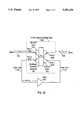
- FIG. 11 depicts a system incorporating a single fiber bi-directional amplifier module 1100 in accordance with the invention.
- a WDM 203 is used to combine two wavelengths of light ( ⁇ 1 and ⁇ 2 ) onto a single fiber 103.
- the transmitter at site A is transmitting light at wavelength ⁇ 1 .
- the receiver at site A is receiving light from site B at wavelength ⁇ 2 .
- ⁇ 1 travels from site A to site B or from west to east on fiber 103
- ⁇ 2 travels from site B to site A in an east to west direction on the fiber 103.
- port 1 connects to the west fiber link 103
- port 2 connects to the east fiber link 103
- port 3 is connected to the input of the amplifier module's EDFA via an optical fiber link 1110
- port 4 is connected to the output of the amplifier module's EDFA via an optical fiber link 1110.
- Site A's 101 WDM filter 203 is a dichroic filter designed to pass a center wavelength ⁇ 2 .
- Site B's 102 WDM filter 201 is also a dichroic filter, but is designed to pass a center wavelength ⁇ 1 .
- the amplifier module's WDM filter 1105 can be constructed from either WDM filter 201 or 203 with the addition of an extra port. The functionality of the invention's four-port WDM will be described below.
- FIG. 12 depicts a four-port WDM filter 1105 in accordance with the invention.
- West fiber link 103 coming from site A, is connected to port 1 1200.
- East fiber link 103 coming from site B, is connected to port 2 1205.
- WDM filter 1100 i.e., the multilayer dichroic substrate 305
- WDM filter 1100 have a designed pass--center--wavelength of ⁇ 2 . This means that signals having a wavelength ⁇ 2 will pass through the WDM filter (i.e., the multilayer dielectric substrate) while signals of all other wavelengths will be reflected.
- Fiber links 1110 can be conventional single-mode optical fiber.
- both wavelengths ⁇ 1 and ⁇ 2 exit the amplifier 401 and are routed to port 4 1215 where they are focused by the "east” lens 310 onto the filter's substrate 305.
- Light of wavelength ⁇ 1 is reflected back through the "east” lens into port 2 1205 where it exits the filter on its way to site B.
- Light of wavelength ⁇ 2 is passed through the substrate and focused by the "west” lens 310 into port 1 1200 where it exits the filter on its way to site A.
- the four-port WDM provides a means to correctly route bi-directional incoming signals so that they pass uni-directionally through a single amplifier, and then are routed into their correct directions for continued transmission.
- Both the four three-port WDM configuration of FIG. 10 and the single four-port WDM configuration of FIGS. 11 and 12 provide the significant advantage of allowing bi-directional transmission through a single amplifier.
- Bi-directional transmission is important in maintaining a single fiber failure transmission philosophy in that, if there is a single fiber failure due to natural failure or human error, only one transmission system will be in jeopardy and will be protected by a conventional 1-by-N protection scheme.
- the four-port WDM device of the invention There are however, several additional advantages provided by the four-port WDM device of the invention.
- One of the more significant advantages is the cost savings in going from four devices to a single device--i.e. , from a system like that shown in FIG. 10 to that of FIG. 11. Additional advantages include: (1) a reduction in the size of packaging that could be obtained when using a single WDM, (2) the improved reliability of a single WDM amplifier module over one with four WDMs, (3) and the reduction in interconnections afforded by the four-port WDM amplifier module. This latter feature impacts both the manufacturing and maintenance costs of an optical transmission system employing amplifier modules.
- the insertion loss of the current invention is improved since the light traveling in either direction encounters the insertion loss of the same filter twice as compared to the insertion loss of four conventional filters in the previous design. Isolation loss of the invention does not degrade since the single filter used offers the same isolation as the cascaded design of four filters.
Abstract
Description
TABLE 1 ______________________________________ Example WDMImplementation WDM Filter 201 WDM Filter 300 (FIG. 2) (FIG. 3) ______________________________________ Fiber 103 Port 1 (320) TX Output Port 2 (325) RX Input Port 3 (330) ______________________________________
                                  TABLE 2
__________________________________________________________________________
Suggested Component Specifications
Block
    Item     Specification
__________________________________________________________________________
1105
    Four-Port WDM
             Dichroic filter Technology.
             Passband: 1557 ± 3 nm Insertion loss: <1.5 dB
             Isolation: >35 dB Back reflecfion: <-40 dB
             Polarization stability: <0.2 dB
103,
    Optical Fiber
             Single-mode fiber such as Corning SMF-28 glass or
             equivalent.
1110
201 Three-Port WDM
             Dichroic filter Technology.
             Passband: 1553 ± 3 nm Insertion loss: <1.5 dB
             Isolation: >35 dB Back reflection: <-40 dB
             Polarization stability: <0.2 dB
203 Three-Port WDM
             Same as block 201 with a passband of 1557 ± 3 nm.
401 EDFA     Operating range: 1530 - 1565 nm Noise figure: <6 dB
    (single pump
             Saturated output power: >12 dB Small signal gain: >25 dB
    version) Polarization stability: <0.3 dB MTBF: >140,000
__________________________________________________________________________
             hours
Claims (7)
Priority Applications (3)
| Application Number | Priority Date | Filing Date | Title |
|---|---|---|---|
| US08/206,423 US5452124A (en) | 1994-03-04 | 1994-03-04 | Unidirectional amplification for bi-directional transmission using wavelength-division multiplexing |
| AU20984/95A AU2098495A (en) | 1994-03-04 | 1995-03-02 | Unidirectional amplification for bi-directional transmission using wavelength-division multiplexing |
| PCT/US1995/002891 WO1995024065A1 (en) | 1994-03-04 | 1995-03-02 | Unidirectional amplification for bi-directional transmission using wavelength-division multiplexing |
Applications Claiming Priority (1)
| Application Number | Priority Date | Filing Date | Title |
|---|---|---|---|
| US08/206,423 US5452124A (en) | 1994-03-04 | 1994-03-04 | Unidirectional amplification for bi-directional transmission using wavelength-division multiplexing |
Publications (1)
| Publication Number | Publication Date |
|---|---|
| US5452124A true US5452124A (en) | 1995-09-19 |
Family
ID=22766308
Family Applications (1)
| Application Number | Title | Priority Date | Filing Date |
|---|---|---|---|
| US08/206,423 Expired - Lifetime US5452124A (en) | 1994-03-04 | 1994-03-04 | Unidirectional amplification for bi-directional transmission using wavelength-division multiplexing |
Country Status (3)
| Country | Link |
|---|---|
| US (1) | US5452124A (en) |
| AU (1) | AU2098495A (en) |
| WO (1) | WO1995024065A1 (en) |
Cited By (75)
| Publication number | Priority date | Publication date | Assignee | Title |
|---|---|---|---|---|
| US5600468A (en) * | 1995-02-13 | 1997-02-04 | Jds Fitel Inc. | Apparatus for converting wavelength-division multiplexed optical signals |
| WO1997021288A1 (en) * | 1995-12-06 | 1997-06-12 | Ericsson Raynet, A Delaware General Partnership | Full duplex optical modem for broadband access network |
| US5657155A (en) * | 1996-08-16 | 1997-08-12 | Jds Fitel Inc. | Optical tap coupler device |
| WO1997041720A2 (en) * | 1996-07-08 | 1997-11-13 | Worldcom Network Services, Inc. | Optical cross-connect module |
| US5703706A (en) * | 1994-09-16 | 1997-12-30 | Varian Associates, Inc. | Spectral modification through phase modulation with spatial extent |
| WO1997050009A1 (en) * | 1996-06-27 | 1997-12-31 | Mci Communications Corporation | Hybrid bi-directional three-color wave division multiplexer |
| US5748363A (en) * | 1995-11-30 | 1998-05-05 | Fitel Inc. | Wavelength dependent crossover system for bi-directional transmission |
| EP0840469A2 (en) * | 1996-10-29 | 1998-05-06 | Corning Incorporated | Device and method to suppress q-switching in an optical amplifying device |
| EP0851617A2 (en) * | 1996-12-30 | 1998-07-01 | AT&T Corp. | Optical arrangement for amplifying WDM signals |
| WO1998028874A1 (en) * | 1996-12-23 | 1998-07-02 | Dsc Communications A/S | A bidirectional router and a method of monodirectional amplification |
| US5801858A (en) * | 1996-06-25 | 1998-09-01 | Northern Telecom Limited | Optical transmission systems using optical amplifiers and wavelength division multiplexing |
| US5815308A (en) * | 1996-05-20 | 1998-09-29 | Northern Telecom Limited | Bidirectional optical amplifier |
| FR2764998A1 (en) * | 1997-06-20 | 1998-12-24 | Thomson Csf | BIDIRECTIONAL OPTICAL AMPLIFICATION SYSTEM |
| WO1999022259A1 (en) * | 1997-10-24 | 1999-05-06 | Mci Worldcom, Inc. | Multiple wavelength bidirectional lightwave amplifier |
| EP0915583A2 (en) * | 1997-10-20 | 1999-05-12 | Fujitsu Limited | Wavelength division multiplex transmission apparatus |
| WO1999053620A2 (en) * | 1998-03-25 | 1999-10-21 | Corning Incorporated | Optical-transmission system having a split-gain amplifier and a signal-modifying device |
| US5995259A (en) * | 1995-01-27 | 1999-11-30 | Pirelli Cavi S.P.A. | Bidirectional optical telecommunication system comprising a bidirectional optical amplifier |
| EP0773641A3 (en) * | 1995-11-07 | 2000-05-17 | AT&T Corp. | Optical communications system using tunable tandem Fabry-Perot etalon |
| US6091542A (en) * | 1997-10-29 | 2000-07-18 | Daewoo Telecom Ltd. | Optical fiber amplifier for amplifying signal lights propagating in two opposite directions |
| US6097533A (en) * | 1997-10-21 | 2000-08-01 | Antec Corporation | Optical amplifier for CATV system with forward and reverse paths |
| EP1065811A2 (en) * | 1999-06-30 | 2001-01-03 | Nortel Networks Limited | Optical amplifiers |
| US6208796B1 (en) | 1998-07-21 | 2001-03-27 | Adc Telecommunications, Inc. | Fiber optic module |
| US6239888B1 (en) | 1998-04-24 | 2001-05-29 | Lightpointe Communications, Inc. | Terrestrial optical communication network of integrated fiber and free-space links which requires no electro-optical conversion between links |
| EP1130820A2 (en) * | 2000-01-18 | 2001-09-05 | Fujitsu Limited | Optical amplification method for two wavelength subbands |
| US6313938B1 (en) * | 1999-01-12 | 2001-11-06 | Oki Electric Industry Co., Ltd. | Planar lightwave circuit module and optical fiber amplifying device |
| US20010038477A1 (en) * | 2000-05-06 | 2001-11-08 | Browave Corporation | High-isolation wavelength managing module for bi-directional wavelength division multiplexing optical communication system |
| US6384948B1 (en) | 1998-09-30 | 2002-05-07 | The United States Of America As Represented By The Secretary Of The Navy | High-sensitivity, high-speed digital optical photoreceiver |
| US6388805B1 (en) | 2001-03-28 | 2002-05-14 | Sycamore Networks, Inc. | Two fiber support with single optical amplifier |
| US20020110313A1 (en) * | 2001-02-12 | 2002-08-15 | Agere Systems Guardian Corp. | Apparatus and method for transmitting optical signals through a single fiber optical network |
| US20020118446A1 (en) * | 2001-02-23 | 2002-08-29 | Chang-Hee Lee | Bi-directional optical-amplifier module |
| US6459528B1 (en) | 2000-05-23 | 2002-10-01 | Avanex Corporation | Optical passive components and bi-directional amplifier |
| US20020149811A1 (en) * | 2001-04-16 | 2002-10-17 | Lightpointe Communications, Inc. | Integrated environmental control and management system for free-space optical communication systems |
| US6483803B1 (en) * | 1996-09-04 | 2002-11-19 | Nortel Networks Limited | Apparatus and method for restoring fiber optic communications network connections |
| US6493117B1 (en) | 1997-08-27 | 2002-12-10 | Nortel Networks Limited | WDM optical network with passive pass-through at each node |
| US6496305B2 (en) | 2001-03-28 | 2002-12-17 | Sycamore Networks, Inc. | Two fiber support with single optical amplifier |
| US6532106B2 (en) * | 2000-06-12 | 2003-03-11 | Korea Institute Of Science And Technology | All-optical gain controlled bidirectional add/drop optical amplifier |
| US20030081290A1 (en) * | 2001-10-30 | 2003-05-01 | Kaoru Kinjo | Method of and device for performing bi-directional transmission using a single-wire |
| US6560387B1 (en) * | 2002-02-11 | 2003-05-06 | Markus P. Hehlen | Doped fiber amplifier utilizing integrated circulator array |
| US20030090765A1 (en) * | 2001-11-09 | 2003-05-15 | Neff Brian W. | Free-space optical communication system |
| US6658210B1 (en) * | 1999-06-04 | 2003-12-02 | Worldcom, Inc. | Interleaved bidirectional WDM channel plan |
| US20030235215A1 (en) * | 2002-03-28 | 2003-12-25 | Carrel John Robert | Apparatus and method for aggregation and transportation for plesiosynchronous framing oriented data formats |
| US20040042067A1 (en) * | 2002-06-04 | 2004-03-04 | Eiselt Michael H. | Apparatus and method for duplex optical transport using a co-directional optical amplifier |
| US6763195B1 (en) | 2000-01-13 | 2004-07-13 | Lightpointe Communications, Inc. | Hybrid wireless optical and radio frequency communication link |
| US6783705B1 (en) | 1997-04-11 | 2004-08-31 | Waters Investments Limited | Calibration medium for wavelength calibration of U.V. absorbance detectors and methods for calibration |
| US20040175187A1 (en) * | 2002-12-13 | 2004-09-09 | Eiselt Michael H. | Single fiber duplex optical transport |
| US20040228632A1 (en) * | 2003-05-14 | 2004-11-18 | Nec Corporation | Single fibre bidirectional optical transmission system and single fibre bidirectional optical amplifier |
| US20050031264A1 (en) * | 2002-03-15 | 2005-02-10 | Pd-Ld, Inc. | Fiber optic devices having volume Bragg grating elements |
| US6868237B2 (en) | 1998-04-24 | 2005-03-15 | Lightpointe Communications, Inc. | Terrestrial optical communication network of integrated fiber and free-space links which requires no electro-optical conversion between links |
| US6888671B2 (en) * | 2001-04-02 | 2005-05-03 | Samsung Electronics Co., Ltd. | Optical amplifier device and bidirectional wavelength division multiplexing optical communication system using the same |
| US6898351B2 (en) | 2000-11-07 | 2005-05-24 | Photon-X, Llc | Optical fiber transmission systems with suppressed light scattering |
| US20050254819A1 (en) * | 2001-12-26 | 2005-11-17 | Takeshi Ota | Optical in-line amplifier and wavelength-division multiplexer |
| US6973268B1 (en) * | 2000-06-30 | 2005-12-06 | Lucent Technologies Inc. | Bi-directional optical transmission using dual channel bands |
| US20060087724A1 (en) * | 2004-10-25 | 2006-04-27 | Ciena Corporation | Bidirectional optical amplifier |
| US7054559B1 (en) * | 1997-09-04 | 2006-05-30 | Mci Communications Corporation | Method and system for modular multiplexing and amplification in a multi-channel plan |
| KR100603595B1 (en) * | 2000-01-17 | 2006-07-24 | 한국전자통신연구원 | Bidirectional two-stage optical amplifier |
| US20060171428A1 (en) * | 2005-02-03 | 2006-08-03 | Pd-Ld, Inc. | High-power, phased-locked, laser arrays |
| US20060215972A1 (en) * | 2002-03-15 | 2006-09-28 | Pd-Ld, Inc. | Fiber optic devices having volume Bragg grating elements |
| US20060251143A1 (en) * | 2003-07-03 | 2006-11-09 | Volodin Boris L | Apparatus and methods for altering a characteristic of light-emitting device |
| US20070003283A1 (en) * | 2005-06-29 | 2007-01-04 | At&T Corp. | Dynamic allocation of bandwidth in a bidirectional optical transmission system |
| US20070098405A1 (en) * | 2005-11-01 | 2007-05-03 | Technology Advancement Group | Method and system for bi-directional communication over a single optical fiber |
| US20080131128A1 (en) * | 2005-01-28 | 2008-06-05 | Takeshi Ota | Optical Signal Transmission Device and Optical Communication Network |
| US20080152352A1 (en) * | 2006-12-21 | 2008-06-26 | Mpb Communications Inc. | Inline pump sharing architecture for remotely-pumped pre- and post-amplifiers |
| US7512343B2 (en) | 2004-07-27 | 2009-03-31 | Ciena Corporation | Bidirectional communication system |
| US7656905B2 (en) | 2002-12-24 | 2010-02-02 | Samir Sheth | Apparatus and method for aggregation and transportation of gigabit ethernet and other packet based data formats |
| US20100164603A1 (en) * | 2008-12-30 | 2010-07-01 | Hafez Walid M | Programmable fuse and anti-fuse elements and methods of changing conduction states of same |
| US7782778B2 (en) | 2002-12-24 | 2010-08-24 | Samir Satish Sheth | Apparatus and method for fibre channel distance extension embedded within an optical transport system |
| US7792003B2 (en) | 2003-09-26 | 2010-09-07 | Pd-Ld, Inc. | Methods for manufacturing volume Bragg grating elements |
| US20110200329A1 (en) * | 2005-11-01 | 2011-08-18 | Technology Advancement Group, Inc. | Method and system for bi-directional communication over a single optical fiber |
| US20120301148A1 (en) * | 2011-05-26 | 2012-11-29 | Fujitsu Limited | Optical signal processing apparatus and optical communication system |
| US8455157B1 (en) | 2007-04-26 | 2013-06-04 | Pd-Ld, Inc. | Methods for improving performance of holographic glasses |
| US20140133847A1 (en) * | 2011-07-01 | 2014-05-15 | Telefonaktiebolaget L.M. Ericsson(Publ) | Device, remote node and methods for pon supervision |
| US20140270782A1 (en) * | 2013-03-12 | 2014-09-18 | Nec Laboratories America, Inc. | Bidirectional Submarine Repeater Using Unidirectional Amplification |
| US9500596B2 (en) | 2011-07-27 | 2016-11-22 | Omnisens Sa | Sensor and method of sensing |
| US20170019176A1 (en) * | 2015-07-13 | 2017-01-19 | Northern Virginia Electric Cooperative | System, apparatus and method for two-way transport of data over a single fiber strand |
| US20170017053A1 (en) * | 2013-03-04 | 2017-01-19 | Alliance Fiber Optic Products, Inc. | Wdm mux/demux on cable and methods of making the same |
Families Citing this family (4)
| Publication number | Priority date | Publication date | Assignee | Title |
|---|---|---|---|---|
| US5689594A (en) * | 1995-12-29 | 1997-11-18 | Mci Communications Corp. | Multiple wavelength bidirectional lightwave amplifier |
| ES2138927B1 (en) * | 1998-02-27 | 2000-09-01 | Telefonica Sa | BIDIRECTIONAL MULTI-CHANNEL OPTICAL OPEN EXTENDER. |
| US6513991B1 (en) * | 2000-01-28 | 2003-02-04 | Agere Systems, Inc. | Semiconductor optical device package |
| CN111711055B (en) * | 2020-06-11 | 2021-09-10 | 武汉光迅科技股份有限公司 | Bidirectional Raman erbium-doped fiber hybrid amplifier, optical signal amplification method and system |
Citations (7)
| Publication number | Priority date | Publication date | Assignee | Title |
|---|---|---|---|---|
| US4849043A (en) * | 1982-09-15 | 1989-07-18 | Instance David John | Method of producing labels |
| US4910727A (en) * | 1986-02-19 | 1990-03-20 | Alcatel N.V. | Optical transceiver having waveguide couplers for filtering and duplexing transmit and receive wavelengths |
| US4972513A (en) * | 1987-07-23 | 1990-11-20 | Kokusai Denshin Denwa Kabushiki Kaisha | Multi-point optical amplification repeating system |
| US5058103A (en) * | 1988-11-08 | 1991-10-15 | Fujitsu Limited | Bidirectional optical transmission system having a light-interruption detecting function |
| US5107358A (en) * | 1988-04-06 | 1992-04-21 | British Telecommunications Public Limited Company | Method and apparatus for transmitting information |
| US5295011A (en) * | 1990-06-25 | 1994-03-15 | Siemens Aktiengesellschaft | Optical duplexer for bidirectional optical information transmission |
| US5375010A (en) * | 1992-02-20 | 1994-12-20 | University Of Southampton | Optical amplifier |
-
1994
- 1994-03-04 US US08/206,423 patent/US5452124A/en not_active Expired - Lifetime
-
1995
- 1995-03-02 WO PCT/US1995/002891 patent/WO1995024065A1/en active Application Filing
- 1995-03-02 AU AU20984/95A patent/AU2098495A/en not_active Abandoned
Patent Citations (7)
| Publication number | Priority date | Publication date | Assignee | Title |
|---|---|---|---|---|
| US4849043A (en) * | 1982-09-15 | 1989-07-18 | Instance David John | Method of producing labels |
| US4910727A (en) * | 1986-02-19 | 1990-03-20 | Alcatel N.V. | Optical transceiver having waveguide couplers for filtering and duplexing transmit and receive wavelengths |
| US4972513A (en) * | 1987-07-23 | 1990-11-20 | Kokusai Denshin Denwa Kabushiki Kaisha | Multi-point optical amplification repeating system |
| US5107358A (en) * | 1988-04-06 | 1992-04-21 | British Telecommunications Public Limited Company | Method and apparatus for transmitting information |
| US5058103A (en) * | 1988-11-08 | 1991-10-15 | Fujitsu Limited | Bidirectional optical transmission system having a light-interruption detecting function |
| US5295011A (en) * | 1990-06-25 | 1994-03-15 | Siemens Aktiengesellschaft | Optical duplexer for bidirectional optical information transmission |
| US5375010A (en) * | 1992-02-20 | 1994-12-20 | University Of Southampton | Optical amplifier |
Cited By (163)
| Publication number | Priority date | Publication date | Assignee | Title |
|---|---|---|---|---|
| US5703706A (en) * | 1994-09-16 | 1997-12-30 | Varian Associates, Inc. | Spectral modification through phase modulation with spatial extent |
| US5995259A (en) * | 1995-01-27 | 1999-11-30 | Pirelli Cavi S.P.A. | Bidirectional optical telecommunication system comprising a bidirectional optical amplifier |
| US5600468A (en) * | 1995-02-13 | 1997-02-04 | Jds Fitel Inc. | Apparatus for converting wavelength-division multiplexed optical signals |
| EP0773641A3 (en) * | 1995-11-07 | 2000-05-17 | AT&T Corp. | Optical communications system using tunable tandem Fabry-Perot etalon |
| US5748363A (en) * | 1995-11-30 | 1998-05-05 | Fitel Inc. | Wavelength dependent crossover system for bi-directional transmission |
| US5694232A (en) * | 1995-12-06 | 1997-12-02 | Ericsson Raynet | Full duplex optical modem for broadband access network |
| WO1997021288A1 (en) * | 1995-12-06 | 1997-06-12 | Ericsson Raynet, A Delaware General Partnership | Full duplex optical modem for broadband access network |
| US5926590A (en) * | 1995-12-29 | 1999-07-20 | Mci Communications Corporation | Power equalizer in a multiple wavelength bidirectional lightwave amplifier |
| US5815308A (en) * | 1996-05-20 | 1998-09-29 | Northern Telecom Limited | Bidirectional optical amplifier |
| US5801858A (en) * | 1996-06-25 | 1998-09-01 | Northern Telecom Limited | Optical transmission systems using optical amplifiers and wavelength division multiplexing |
| US6067179A (en) * | 1996-06-25 | 2000-05-23 | Nortel Networks Corporation | Optical transmission systems using optical amplifiers and wavelength division multiplexing |
| US6101016A (en) * | 1996-06-25 | 2000-08-08 | Nortel Networks Corporation | Optical transmission systems using optical amplifiers and wavelength division multiplexing |
| CN100431289C (en) * | 1996-06-25 | 2008-11-05 | 北方电讯网络有限公司 | Optical transmission systems using optical amplifiers and wavelength division multiplexing |
| WO1997050009A1 (en) * | 1996-06-27 | 1997-12-31 | Mci Communications Corporation | Hybrid bi-directional three-color wave division multiplexer |
| WO1997041720A3 (en) * | 1996-07-08 | 1997-12-11 | Worldcom Network Services Inc | Optical cross-connect module |
| US5774245A (en) * | 1996-07-08 | 1998-06-30 | Worldcom Network Services, Inc. | Optical cross-connect module |
| WO1997041720A2 (en) * | 1996-07-08 | 1997-11-13 | Worldcom Network Services, Inc. | Optical cross-connect module |
| US5657155A (en) * | 1996-08-16 | 1997-08-12 | Jds Fitel Inc. | Optical tap coupler device |
| US6483803B1 (en) * | 1996-09-04 | 2002-11-19 | Nortel Networks Limited | Apparatus and method for restoring fiber optic communications network connections |
| US5801879A (en) * | 1996-10-29 | 1998-09-01 | Corning Incorporated | Device and method to supress Q-switching in an optical amplifying device |
| EP0840469A2 (en) * | 1996-10-29 | 1998-05-06 | Corning Incorporated | Device and method to suppress q-switching in an optical amplifying device |
| EP0840469A3 (en) * | 1996-10-29 | 2000-01-05 | Corning Incorporated | Device and method to suppress q-switching in an optical amplifying device |
| WO1998028874A1 (en) * | 1996-12-23 | 1998-07-02 | Dsc Communications A/S | A bidirectional router and a method of monodirectional amplification |
| US6724995B1 (en) | 1996-12-23 | 2004-04-20 | Tellabs Denmark A/S | Bidirectional router and a method of bidirectional amplification |
| EP0851617A3 (en) * | 1996-12-30 | 1999-07-14 | AT&T Corp. | Optical arrangement for amplifying WDM signals |
| EP0851617A2 (en) * | 1996-12-30 | 1998-07-01 | AT&T Corp. | Optical arrangement for amplifying WDM signals |
| US6783705B1 (en) | 1997-04-11 | 2004-08-31 | Waters Investments Limited | Calibration medium for wavelength calibration of U.V. absorbance detectors and methods for calibration |
| WO1998059398A1 (en) * | 1997-06-20 | 1998-12-30 | Thomson-Csf | Bi-directional optical amplification system |
| FR2764998A1 (en) * | 1997-06-20 | 1998-12-24 | Thomson Csf | BIDIRECTIONAL OPTICAL AMPLIFICATION SYSTEM |
| US6172802B1 (en) * | 1997-06-20 | 2001-01-09 | Thomson-Csf | Bidirectional optical amplification system |
| US6631018B1 (en) | 1997-08-27 | 2003-10-07 | Nortel Networks Limited | WDM optical network with passive pass-through at each node |
| US6563615B2 (en) | 1997-08-27 | 2003-05-13 | Nortel Networks Limited | Technique for detecting noise on a data channel |
| US6493117B1 (en) | 1997-08-27 | 2002-12-10 | Nortel Networks Limited | WDM optical network with passive pass-through at each node |
| US6529300B1 (en) | 1997-08-27 | 2003-03-04 | Nortel Networks Limited | WDM optical network with passive pass-through at each node |
| US6775479B2 (en) | 1997-08-27 | 2004-08-10 | Nortel Networks Corporation | WDM optical network with passive pass-through at each node |
| US6757498B2 (en) | 1997-08-27 | 2004-06-29 | Nortel Networks Limited | WDM optical network with passive pass-through at each node |
| US6751418B2 (en) | 1997-08-27 | 2004-06-15 | Nortel Networks Limited | WDM optical network with passive pass-through at each node |
| US6748174B2 (en) | 1997-08-27 | 2004-06-08 | Nortel Networks Limited | WDM optical network with passive pass-through at each node |
| US6556321B1 (en) | 1997-08-27 | 2003-04-29 | Nortel Networks Limited | WDM optical network and switching node with pilot tone communications |
| US6795652B2 (en) | 1997-08-27 | 2004-09-21 | Nortel Networks Limited | WDM optical network with passive pass-through at each node |
| US6892032B2 (en) | 1997-08-27 | 2005-05-10 | Nortel Networks Limited | WDM optical network with passive pass-through at each node |
| US7054559B1 (en) * | 1997-09-04 | 2006-05-30 | Mci Communications Corporation | Method and system for modular multiplexing and amplification in a multi-channel plan |
| EP0915583A2 (en) * | 1997-10-20 | 1999-05-12 | Fujitsu Limited | Wavelength division multiplex transmission apparatus |
| EP0915583A3 (en) * | 1997-10-20 | 2001-10-10 | Fujitsu Limited | Wavelength division multiplex transmission apparatus |
| US6097533A (en) * | 1997-10-21 | 2000-08-01 | Antec Corporation | Optical amplifier for CATV system with forward and reverse paths |
| WO1999022259A1 (en) * | 1997-10-24 | 1999-05-06 | Mci Worldcom, Inc. | Multiple wavelength bidirectional lightwave amplifier |
| US6091542A (en) * | 1997-10-29 | 2000-07-18 | Daewoo Telecom Ltd. | Optical fiber amplifier for amplifying signal lights propagating in two opposite directions |
| WO1999053620A2 (en) * | 1998-03-25 | 1999-10-21 | Corning Incorporated | Optical-transmission system having a split-gain amplifier and a signal-modifying device |
| WO1999053620A3 (en) * | 1998-03-25 | 2000-03-30 | Corning Inc | Optical-transmission system having a split-gain amplifier and a signal-modifying device |
| US6173094B1 (en) | 1998-03-25 | 2001-01-09 | Corning Incorporated | Optical-transmission system having a split-gain amplifier and a signal-modifying device |
| US6934477B2 (en) | 1998-04-24 | 2005-08-23 | Lightpointe Communications, Inc. | Method and apparatus for free-space optical communication without eletro-optical conversion |
| US6239888B1 (en) | 1998-04-24 | 2001-05-29 | Lightpointe Communications, Inc. | Terrestrial optical communication network of integrated fiber and free-space links which requires no electro-optical conversion between links |
| US6868237B2 (en) | 1998-04-24 | 2005-03-15 | Lightpointe Communications, Inc. | Terrestrial optical communication network of integrated fiber and free-space links which requires no electro-optical conversion between links |
| US6462847B2 (en) | 1998-04-24 | 2002-10-08 | Lightpointe Communications, Inc. | Method and apparatus for free-space optical communication without electro-optical conversion |
| US6208796B1 (en) | 1998-07-21 | 2001-03-27 | Adc Telecommunications, Inc. | Fiber optic module |
| US6307998B2 (en) | 1998-07-21 | 2001-10-23 | Adc Telecommunications, Inc. | Fiber optic module including lens cap |
| US6384948B1 (en) | 1998-09-30 | 2002-05-07 | The United States Of America As Represented By The Secretary Of The Navy | High-sensitivity, high-speed digital optical photoreceiver |
| US6313938B1 (en) * | 1999-01-12 | 2001-11-06 | Oki Electric Industry Co., Ltd. | Planar lightwave circuit module and optical fiber amplifying device |
| US6658210B1 (en) * | 1999-06-04 | 2003-12-02 | Worldcom, Inc. | Interleaved bidirectional WDM channel plan |
| US6275331B1 (en) * | 1999-06-30 | 2001-08-14 | Nortel Networks Limited | Optical amplifiers |
| EP1065811A2 (en) * | 1999-06-30 | 2001-01-03 | Nortel Networks Limited | Optical amplifiers |
| EP1065811A3 (en) * | 1999-06-30 | 2001-02-21 | Nortel Networks Limited | Optical amplifiers |
| US20040208591A1 (en) * | 2000-01-13 | 2004-10-21 | Lightpointe Communications, Inc. | Hybrid wireless optical and radio frequency communication link |
| US7110678B2 (en) | 2000-01-13 | 2006-09-19 | Lightpointe Communications, Inc. | Hybrid wireless optical and radio frequency communication link |
| US6763195B1 (en) | 2000-01-13 | 2004-07-13 | Lightpointe Communications, Inc. | Hybrid wireless optical and radio frequency communication link |
| KR100603595B1 (en) * | 2000-01-17 | 2006-07-24 | 한국전자통신연구원 | Bidirectional two-stage optical amplifier |
| EP1130820A2 (en) * | 2000-01-18 | 2001-09-05 | Fujitsu Limited | Optical amplification method for two wavelength subbands |
| EP1130820A3 (en) * | 2000-01-18 | 2004-07-28 | Fujitsu Limited | Optical amplification method for two wavelength subbands |
| US20010038477A1 (en) * | 2000-05-06 | 2001-11-08 | Browave Corporation | High-isolation wavelength managing module for bi-directional wavelength division multiplexing optical communication system |
| US20040051939A1 (en) * | 2000-05-23 | 2004-03-18 | Avanex Corporation | Optical passive components and bi-directional amplifier |
| US6459528B1 (en) | 2000-05-23 | 2002-10-01 | Avanex Corporation | Optical passive components and bi-directional amplifier |
| US6643056B2 (en) | 2000-05-23 | 2003-11-04 | Avanex Corporation | Optical passive components and bi-directional amplifier |
| US6532106B2 (en) * | 2000-06-12 | 2003-03-11 | Korea Institute Of Science And Technology | All-optical gain controlled bidirectional add/drop optical amplifier |
| US6973268B1 (en) * | 2000-06-30 | 2005-12-06 | Lucent Technologies Inc. | Bi-directional optical transmission using dual channel bands |
| US6898351B2 (en) | 2000-11-07 | 2005-05-24 | Photon-X, Llc | Optical fiber transmission systems with suppressed light scattering |
| US20050207703A1 (en) * | 2000-11-07 | 2005-09-22 | Photon-X, Llc | Method of suppressing non-linearities in an optical communication system |
| US6839517B2 (en) * | 2001-02-12 | 2005-01-04 | Agere Systems Inc. | Apparatus and method for transmitting optical signals through a single fiber optical network |
| US20020110313A1 (en) * | 2001-02-12 | 2002-08-15 | Agere Systems Guardian Corp. | Apparatus and method for transmitting optical signals through a single fiber optical network |
| KR100387072B1 (en) * | 2001-02-23 | 2003-06-12 | 삼성전자주식회사 | Bidirectional Optical Amplifier |
| US20020118446A1 (en) * | 2001-02-23 | 2002-08-29 | Chang-Hee Lee | Bi-directional optical-amplifier module |
| US6894830B2 (en) | 2001-02-23 | 2005-05-17 | Samsung Electronics Co, Ltd. | Bi-directional optical-amplifier module |
| US6388805B1 (en) | 2001-03-28 | 2002-05-14 | Sycamore Networks, Inc. | Two fiber support with single optical amplifier |
| US6496305B2 (en) | 2001-03-28 | 2002-12-17 | Sycamore Networks, Inc. | Two fiber support with single optical amplifier |
| US6888671B2 (en) * | 2001-04-02 | 2005-05-03 | Samsung Electronics Co., Ltd. | Optical amplifier device and bidirectional wavelength division multiplexing optical communication system using the same |
| US20020149811A1 (en) * | 2001-04-16 | 2002-10-17 | Lightpointe Communications, Inc. | Integrated environmental control and management system for free-space optical communication systems |
| US6889009B2 (en) | 2001-04-16 | 2005-05-03 | Lightpointe Communications, Inc. | Integrated environmental control and management system for free-space optical communication systems |
| US20030081290A1 (en) * | 2001-10-30 | 2003-05-01 | Kaoru Kinjo | Method of and device for performing bi-directional transmission using a single-wire |
| US7269349B2 (en) * | 2001-10-30 | 2007-09-11 | Mitsubishi Denki Kabushiki Kaisha | Method of and device for performing bi-directional transmission using a single-wire |
| US20030090765A1 (en) * | 2001-11-09 | 2003-05-15 | Neff Brian W. | Free-space optical communication system |
| US20050254819A1 (en) * | 2001-12-26 | 2005-11-17 | Takeshi Ota | Optical in-line amplifier and wavelength-division multiplexer |
| US6560387B1 (en) * | 2002-02-11 | 2003-05-06 | Markus P. Hehlen | Doped fiber amplifier utilizing integrated circulator array |
| US7949216B2 (en) | 2002-03-15 | 2011-05-24 | Pd-Ld, Inc. | Bragg grating elements for optical devices |
| US7528385B2 (en) | 2002-03-15 | 2009-05-05 | Pd-Ld, Inc. | Fiber optic devices having volume Bragg grating elements |
| US20050031264A1 (en) * | 2002-03-15 | 2005-02-10 | Pd-Ld, Inc. | Fiber optic devices having volume Bragg grating elements |
| US20060215972A1 (en) * | 2002-03-15 | 2006-09-28 | Pd-Ld, Inc. | Fiber optic devices having volume Bragg grating elements |
| US7817888B2 (en) | 2002-03-15 | 2010-10-19 | Pd-Ld, Inc. | Bragg grating elements for optical devices |
| US20090086297A1 (en) * | 2002-03-15 | 2009-04-02 | Pd-Ld, Inc. | Bragg grating elements for optical devices |
| US20030235215A1 (en) * | 2002-03-28 | 2003-12-25 | Carrel John Robert | Apparatus and method for aggregation and transportation for plesiosynchronous framing oriented data formats |
| US20040042067A1 (en) * | 2002-06-04 | 2004-03-04 | Eiselt Michael H. | Apparatus and method for duplex optical transport using a co-directional optical amplifier |
| US20040175187A1 (en) * | 2002-12-13 | 2004-09-09 | Eiselt Michael H. | Single fiber duplex optical transport |
| US7421207B2 (en) | 2002-12-13 | 2008-09-02 | Pivotal Decisions Llc | Single fiber duplex optical transport |
| US7840139B2 (en) | 2002-12-13 | 2010-11-23 | Eiselt Michael H | Single fiber duplex optical transport |
| US7656905B2 (en) | 2002-12-24 | 2010-02-02 | Samir Sheth | Apparatus and method for aggregation and transportation of gigabit ethernet and other packet based data formats |
| US7782778B2 (en) | 2002-12-24 | 2010-08-24 | Samir Satish Sheth | Apparatus and method for fibre channel distance extension embedded within an optical transport system |
| US7734180B2 (en) * | 2003-05-14 | 2010-06-08 | Nec Corporation | Single fibre bidirectional optical transmission system and single fibre bidirectional optical amplifier |
| CN100345345C (en) * | 2003-05-14 | 2007-10-24 | 日本电气株式会社 | Single optical fibre bidirectional optical transmission system and single optical fibre bidirectional optical amplifier |
| US20040228632A1 (en) * | 2003-05-14 | 2004-11-18 | Nec Corporation | Single fibre bidirectional optical transmission system and single fibre bidirectional optical amplifier |
| US7633985B2 (en) | 2003-07-03 | 2009-12-15 | Pd-Ld, Inc. | Apparatus and methods for altering a characteristic of light-emitting device |
| US20060256827A1 (en) * | 2003-07-03 | 2006-11-16 | Volodin Boris L | Use of bragg grating elements for the conditioning of laser emission characteristics |
| US10205295B2 (en) | 2003-07-03 | 2019-02-12 | Necsel Intellectual Property, Inc. | Chirped Bragg grating elements |
| US20080253424A1 (en) * | 2003-07-03 | 2008-10-16 | Boris Leonidovich Volodin | Use of Volume Bragg Gratings For The Conditioning Of Laser Emission Characteristics |
| US20080267246A1 (en) * | 2003-07-03 | 2008-10-30 | Pd-Ld, Inc. | Apparatus And Methods For Altering A Characteristic Of A Light-Emitting Device |
| US8306088B2 (en) | 2003-07-03 | 2012-11-06 | Pd-Ld, Inc. | Bragg grating elements for the conditioning of laser emission characteristics |
| US20060251143A1 (en) * | 2003-07-03 | 2006-11-09 | Volodin Boris L | Apparatus and methods for altering a characteristic of light-emitting device |
| US9793674B2 (en) | 2003-07-03 | 2017-10-17 | Necsel Intellectual Property, Inc. | Chirped Bragg grating elements |
| US20070047608A1 (en) * | 2003-07-03 | 2007-03-01 | Pd-Ld, Inc. | Use of volume bragg gratings for the conditioning of laser emission characteristics |
| US7545844B2 (en) | 2003-07-03 | 2009-06-09 | Pd-Ld, Inc. | Use of Bragg grating elements for the conditioning of laser emission characteristics |
| US7590162B2 (en) | 2003-07-03 | 2009-09-15 | Pd-Ld, Inc. | Chirped bragg grating elements |
| US7796673B2 (en) | 2003-07-03 | 2010-09-14 | Pd-Ld, Inc. | Apparatus and methods for altering a characteristic of a light-emitting device |
| US20060251134A1 (en) * | 2003-07-03 | 2006-11-09 | Volodin Boris L | Apparatus and methods for altering a characteristic of a light-emitting device |
| US20060256830A1 (en) * | 2003-07-03 | 2006-11-16 | Pd-Ld, Inc. | Bragg grating elements for the conditioning of laser emission characteristics |
| US7697589B2 (en) | 2003-07-03 | 2010-04-13 | Pd-Ld, Inc. | Use of volume Bragg gratings for the conditioning of laser emission characteristics |
| US7792003B2 (en) | 2003-09-26 | 2010-09-07 | Pd-Ld, Inc. | Methods for manufacturing volume Bragg grating elements |
| US7512343B2 (en) | 2004-07-27 | 2009-03-31 | Ciena Corporation | Bidirectional communication system |
| US7630127B2 (en) | 2004-10-25 | 2009-12-08 | Ciena Corporation | Bidirectional optical amplifier |
| US7408702B2 (en) | 2004-10-25 | 2008-08-05 | Ciena Corporation | Bidirectional optical amplifier |
| US20060087724A1 (en) * | 2004-10-25 | 2006-04-27 | Ciena Corporation | Bidirectional optical amplifier |
| US7787772B2 (en) * | 2005-01-28 | 2010-08-31 | Canare Electric Co., Ltd. | Optical signal transmission device and optical communication network |
| US20080131128A1 (en) * | 2005-01-28 | 2008-06-05 | Takeshi Ota | Optical Signal Transmission Device and Optical Communication Network |
| US8340150B2 (en) | 2005-02-03 | 2012-12-25 | Pd-Ld, Inc. | High-power, phase-locked, laser arrays |
| US20060171428A1 (en) * | 2005-02-03 | 2006-08-03 | Pd-Ld, Inc. | High-power, phased-locked, laser arrays |
| US9379514B2 (en) | 2005-02-03 | 2016-06-28 | Pd-Ld, Inc. | High-power, phased-locked, laser arrays |
| US7949030B2 (en) | 2005-02-03 | 2011-05-24 | Pd-Ld, Inc. | High-power, phased-locked, laser arrays |
| US9748730B2 (en) | 2005-02-03 | 2017-08-29 | Necsel Intellectual Property, Inc. | High-power, phased-locked, laser arrays |
| US9130349B2 (en) | 2005-02-03 | 2015-09-08 | Pd-Ld, Inc. | High-power, phase-locked, laser arrays |
| US8755421B2 (en) | 2005-02-03 | 2014-06-17 | Pd-Ld, Inc. | High-power, phase-locked, laser arrays |
| US20070003283A1 (en) * | 2005-06-29 | 2007-01-04 | At&T Corp. | Dynamic allocation of bandwidth in a bidirectional optical transmission system |
| US20110200329A1 (en) * | 2005-11-01 | 2011-08-18 | Technology Advancement Group, Inc. | Method and system for bi-directional communication over a single optical fiber |
| US7840138B2 (en) | 2005-11-01 | 2010-11-23 | Technology Advancement Group, Inc. | Method and system for bi-directional communication over a single optical fiber |
| US8600238B2 (en) | 2005-11-01 | 2013-12-03 | Technology Advancement Group, Inc. | Method and system for bi-directional communication over a single optical fiber |
| US20070098405A1 (en) * | 2005-11-01 | 2007-05-03 | Technology Advancement Group | Method and system for bi-directional communication over a single optical fiber |
| US20080152352A1 (en) * | 2006-12-21 | 2008-06-26 | Mpb Communications Inc. | Inline pump sharing architecture for remotely-pumped pre- and post-amplifiers |
| US8081880B2 (en) * | 2006-12-21 | 2011-12-20 | Mpb Communications Inc. | Inline pump sharing architecture for remotely-pumped pre- and post-amplifiers |
| US9120696B2 (en) | 2007-04-26 | 2015-09-01 | Pd-Ld, Inc. | Methods for improving performance of holographic glasses |
| US8455157B1 (en) | 2007-04-26 | 2013-06-04 | Pd-Ld, Inc. | Methods for improving performance of holographic glasses |
| US9377757B2 (en) | 2007-04-26 | 2016-06-28 | Pd-Ld, Inc. | Methods for improving performance of holographic glasses |
| US20100164603A1 (en) * | 2008-12-30 | 2010-07-01 | Hafez Walid M | Programmable fuse and anti-fuse elements and methods of changing conduction states of same |
| US8676059B2 (en) * | 2011-05-26 | 2014-03-18 | Fujitsu Limited | Optical signal processing apparatus and optical communication system |
| US20120301148A1 (en) * | 2011-05-26 | 2012-11-29 | Fujitsu Limited | Optical signal processing apparatus and optical communication system |
| US20140133847A1 (en) * | 2011-07-01 | 2014-05-15 | Telefonaktiebolaget L.M. Ericsson(Publ) | Device, remote node and methods for pon supervision |
| US9344188B2 (en) * | 2011-07-01 | 2016-05-17 | Telefonaktiebolaget L M Ericsson (Publ) | Device, remote node and methods for PON supervision |
| US9500596B2 (en) | 2011-07-27 | 2016-11-22 | Omnisens Sa | Sensor and method of sensing |
| US20170017053A1 (en) * | 2013-03-04 | 2017-01-19 | Alliance Fiber Optic Products, Inc. | Wdm mux/demux on cable and methods of making the same |
| US9983374B2 (en) * | 2013-03-04 | 2018-05-29 | Alliance Fiber Optic Products, Inc. | WDM Mux/DeMux on cable and methods of making the same |
| US9184849B2 (en) * | 2013-03-12 | 2015-11-10 | Nec Laboratories America, Inc. | Bidirectional submarine repeater using unidirectional amplification |
| US20140270782A1 (en) * | 2013-03-12 | 2014-09-18 | Nec Laboratories America, Inc. | Bidirectional Submarine Repeater Using Unidirectional Amplification |
| US20170019176A1 (en) * | 2015-07-13 | 2017-01-19 | Northern Virginia Electric Cooperative | System, apparatus and method for two-way transport of data over a single fiber strand |
| US9847838B2 (en) * | 2015-07-13 | 2017-12-19 | Northern Virginia Electric Cooperative | System, apparatus and method for two-way transport of data over a single fiber strand |
| US20180109321A1 (en) * | 2015-07-13 | 2018-04-19 | Northern Virginia Electric Cooperative | System, apparatus and method for two-way transport of data over a single fiber strand |
| US10469169B2 (en) * | 2015-07-13 | 2019-11-05 | Novec Solutions, Inc. | System, apparatus and method for two-way transport of data over a single fiber strand |
| US20200067599A1 (en) * | 2015-07-13 | 2020-02-27 | Novec Solutions, Inc. | System, apparatus and method for two-way transport of data over a single fiber strand |
| US10826611B2 (en) * | 2015-07-13 | 2020-11-03 | Novec Solutions, Inc. | System, apparatus and method for two-way transport of data over a single fiber strand |
| JP2022022319A (en) * | 2015-07-13 | 2022-02-03 | ノーザン バージニア エレクトリック コーポレイティブ | Bi-directional transmission system of data over single fiber strand, device, and method |
Also Published As
| Publication number | Publication date |
|---|---|
| AU2098495A (en) | 1995-09-18 |
| WO1995024065A1 (en) | 1995-09-08 |
Similar Documents
| Publication | Publication Date | Title |
|---|---|---|
| US5452124A (en) | Unidirectional amplification for bi-directional transmission using wavelength-division multiplexing | |
| US5748363A (en) | Wavelength dependent crossover system for bi-directional transmission | |
| US5532864A (en) | Optical monitoring channel for wavelength division multiplexed optical communication system | |
| US5812306A (en) | Bidirectional WDM optical communication systems with bidirectional optical amplifiers | |
| US5742416A (en) | Bidirectional WDM optical communication systems with bidirectional optical amplifiers | |
| US5801858A (en) | Optical transmission systems using optical amplifiers and wavelength division multiplexing | |
| US6922529B2 (en) | Optical communications systems, devices, and methods | |
| US6411407B1 (en) | Method for providing a bidirectional optical supervisory channel | |
| KR100334432B1 (en) | Bidirectional add/drop optical amplifier module using one arrayed-waveguide grating multiplexer | |
| JPH01115230A (en) | Optical fiber communication lan | |
| WO1995015625A1 (en) | Bidirectional optical amplifier | |
| US20010048799A1 (en) | Optical communication system | |
| JP4798997B2 (en) | Method and apparatus for distributing pump energy from a single pump device to optical fibers located in different pairs of fibers | |
| US6327062B1 (en) | Optical communication system | |
| US6381049B1 (en) | Multi-port optical multiplexer element | |
| JPH03269522A (en) | Amplifier device for wavelength multiplex optical transmission line | |
| US6873758B1 (en) | Optical add-drop filter | |
| JP4588257B2 (en) | Optical amplification system using Raman amplification | |
| JP3149916B2 (en) | WDM optical repeater | |
| CA2211648A1 (en) | Wavelength dependent crossover system for bi-directional transmission | |
| JP4607892B2 (en) | Optical neckwork and optical node work amplifier node | |
| US20020033999A1 (en) | C and L band laminated fabric optical amplifier | |
| EP1654816B1 (en) | Wavelength-selective optical signal processing device | |
| KR20000074542A (en) | Bi-directional Optical Amplifier Using Uni-directional Optical Amplifier | |
| CA2272469A1 (en) | Optical communication system |
Legal Events
| Date | Code | Title | Description |
|---|---|---|---|
| AS | Assignment |
Owner name: WILLIAMS TELECOMMUNICATIONS GROUP, INC., OKLAHOMA Free format text: ASSIGNMENT OF ASSIGNORS INTEREST;ASSIGNOR:BAKER, PHILLLIP EATHAN;REEL/FRAME:007212/0192 Effective date: 19940502 |
|
| REMI | Maintenance fee reminder mailed | ||
| FP | Lapsed due to failure to pay maintenance fee |
Effective date: 19990919 |
|
| AS | Assignment |
Owner name: LDDS COMMUNICATIONS, INC., MISSISSIPPI Free format text: MERGER;ASSIGNOR:WILLIAMS TELECOMMUNICATIONS GROUP, INC.;REEL/FRAME:011369/0197 Effective date: 19950222 |
|
| FEPP | Fee payment procedure |
Free format text: PETITION RELATED TO MAINTENANCE FEES FILED (ORIGINAL EVENT CODE: PMFP); ENTITY STATUS OF PATENT OWNER: LARGE ENTITY |
|
| FEPP | Fee payment procedure |
Free format text: PETITION RELATED TO MAINTENANCE FEES GRANTED (ORIGINAL EVENT CODE: PMFG); ENTITY STATUS OF PATENT OWNER: LARGE ENTITY |
|
| AS | Assignment |
Owner name: WORLDCOM, INC., MISSISSIPPI Free format text: CHANGE OF NAME;ASSIGNOR:LDDS COMMUNICATIONS, INC.;REEL/FRAME:011347/0357 Effective date: 20000525 |
|
| FPAY | Fee payment |
Year of fee payment: 4 |
|
| SULP | Surcharge for late payment | ||
| STCF | Information on status: patent grant |
Free format text: PATENTED CASE |
|
| PRDP | Patent reinstated due to the acceptance of a late maintenance fee |
Effective date: 20010427 |
|
| FPAY | Fee payment |
Year of fee payment: 8 |
|
| FPAY | Fee payment |
Year of fee payment: 12 |
|
| FEPP | Fee payment procedure |
Free format text: PAYER NUMBER DE-ASSIGNED (ORIGINAL EVENT CODE: RMPN); ENTITY STATUS OF PATENT OWNER: LARGE ENTITY Free format text: PAYOR NUMBER ASSIGNED (ORIGINAL EVENT CODE: ASPN); ENTITY STATUS OF PATENT OWNER: LARGE ENTITY |
|
| AS | Assignment |
Owner name: MCI, INC., VIRGINIA Free format text: MERGER;ASSIGNOR:WORLDCOM, INC.;REEL/FRAME:027933/0995 Effective date: 20040419 Owner name: VERIZON BUSINESS GLOBAL LLC, NEW JERSEY Free format text: CHANGE OF NAME;ASSIGNOR:MCI, LLC;REEL/FRAME:027934/0592 Effective date: 20061120 Owner name: MCI, LLC, VIRGINIA Free format text: MERGER;ASSIGNOR:MCI, INC.;REEL/FRAME:027934/0060 Effective date: 20060106 |
|
| AS | Assignment |
Owner name: VERIZON PATENT AND LICENSING INC., NEW JERSEY Free format text: ASSIGNMENT OF ASSIGNORS INTEREST;ASSIGNOR:VERIZON BUSINESS GLOBAL LLC;REEL/FRAME:028969/0914 Effective date: 20120917 |
|
| AS | Assignment |
Owner name: TEKLA PEHR LLC, DELAWARE Free format text: ASSIGNMENT OF ASSIGNORS INTEREST;ASSIGNOR:VERIZON PATENT AND LICENSING INC.;REEL/FRAME:029368/0460 Effective date: 20120918 |