US5743264A - Method of imaging an ankle of a patient - Google Patents
Method of imaging an ankle of a patient Download PDFInfo
- Publication number
- US5743264A US5743264A US08/456,817 US45681795A US5743264A US 5743264 A US5743264 A US 5743264A US 45681795 A US45681795 A US 45681795A US 5743264 A US5743264 A US 5743264A
- Authority
- US
- United States
- Prior art keywords
- patient
- movable member
- ankle
- foot
- imaging
- Prior art date
- Legal status (The legal status is an assumption and is not a legal conclusion. Google has not performed a legal analysis and makes no representation as to the accuracy of the status listed.)
- Expired - Lifetime
Links
Images


Classifications
-
- A—HUMAN NECESSITIES
- A61—MEDICAL OR VETERINARY SCIENCE; HYGIENE
- A61B—DIAGNOSIS; SURGERY; IDENTIFICATION
- A61B5/00—Measuring for diagnostic purposes; Identification of persons
- A61B5/05—Detecting, measuring or recording for diagnosis by means of electric currents or magnetic fields; Measuring using microwaves or radio waves
- A61B5/055—Detecting, measuring or recording for diagnosis by means of electric currents or magnetic fields; Measuring using microwaves or radio waves involving electronic [EMR] or nuclear [NMR] magnetic resonance, e.g. magnetic resonance imaging
-
- A—HUMAN NECESSITIES
- A61—MEDICAL OR VETERINARY SCIENCE; HYGIENE
- A61B—DIAGNOSIS; SURGERY; IDENTIFICATION
- A61B6/00—Apparatus for radiation diagnosis, e.g. combined with radiation therapy equipment
- A61B6/04—Positioning of patients; Tiltable beds or the like
- A61B6/0407—Supports, e.g. tables or beds, for the body or parts of the body
- A61B6/0421—Supports, e.g. tables or beds, for the body or parts of the body with immobilising means
-
- A—HUMAN NECESSITIES
- A61—MEDICAL OR VETERINARY SCIENCE; HYGIENE
- A61B—DIAGNOSIS; SURGERY; IDENTIFICATION
- A61B6/00—Apparatus for radiation diagnosis, e.g. combined with radiation therapy equipment
- A61B6/04—Positioning of patients; Tiltable beds or the like
- A61B6/0485—Inflatable rests for lifting of patients
-
- A—HUMAN NECESSITIES
- A61—MEDICAL OR VETERINARY SCIENCE; HYGIENE
- A61G—TRANSPORT, PERSONAL CONVEYANCES, OR ACCOMMODATION SPECIALLY ADAPTED FOR PATIENTS OR DISABLED PERSONS; OPERATING TABLES OR CHAIRS; CHAIRS FOR DENTISTRY; FUNERAL DEVICES
- A61G13/00—Operating tables; Auxiliary appliances therefor
- A61G13/10—Parts, details or accessories
- A61G13/12—Rests specially adapted therefor; Arrangements of patient-supporting surfaces
-
- A—HUMAN NECESSITIES
- A61—MEDICAL OR VETERINARY SCIENCE; HYGIENE
- A61B—DIAGNOSIS; SURGERY; IDENTIFICATION
- A61B5/00—Measuring for diagnostic purposes; Identification of persons
- A61B5/45—For evaluating or diagnosing the musculoskeletal system or teeth
- A61B5/4528—Joints
-
- A—HUMAN NECESSITIES
- A61—MEDICAL OR VETERINARY SCIENCE; HYGIENE
- A61G—TRANSPORT, PERSONAL CONVEYANCES, OR ACCOMMODATION SPECIALLY ADAPTED FOR PATIENTS OR DISABLED PERSONS; OPERATING TABLES OR CHAIRS; CHAIRS FOR DENTISTRY; FUNERAL DEVICES
- A61G13/00—Operating tables; Auxiliary appliances therefor
- A61G13/10—Parts, details or accessories
- A61G13/12—Rests specially adapted therefor; Arrangements of patient-supporting surfaces
- A61G13/1205—Rests specially adapted therefor; Arrangements of patient-supporting surfaces for specific parts of the body
- A61G13/121—Head or neck
-
- A—HUMAN NECESSITIES
- A61—MEDICAL OR VETERINARY SCIENCE; HYGIENE
- A61G—TRANSPORT, PERSONAL CONVEYANCES, OR ACCOMMODATION SPECIALLY ADAPTED FOR PATIENTS OR DISABLED PERSONS; OPERATING TABLES OR CHAIRS; CHAIRS FOR DENTISTRY; FUNERAL DEVICES
- A61G13/00—Operating tables; Auxiliary appliances therefor
- A61G13/10—Parts, details or accessories
- A61G13/12—Rests specially adapted therefor; Arrangements of patient-supporting surfaces
- A61G13/1205—Rests specially adapted therefor; Arrangements of patient-supporting surfaces for specific parts of the body
- A61G13/1225—Back
-
- A—HUMAN NECESSITIES
- A61—MEDICAL OR VETERINARY SCIENCE; HYGIENE
- A61G—TRANSPORT, PERSONAL CONVEYANCES, OR ACCOMMODATION SPECIALLY ADAPTED FOR PATIENTS OR DISABLED PERSONS; OPERATING TABLES OR CHAIRS; CHAIRS FOR DENTISTRY; FUNERAL DEVICES
- A61G13/00—Operating tables; Auxiliary appliances therefor
- A61G13/10—Parts, details or accessories
- A61G13/12—Rests specially adapted therefor; Arrangements of patient-supporting surfaces
- A61G13/1205—Rests specially adapted therefor; Arrangements of patient-supporting surfaces for specific parts of the body
- A61G13/1235—Arms
-
- A—HUMAN NECESSITIES
- A61—MEDICAL OR VETERINARY SCIENCE; HYGIENE
- A61G—TRANSPORT, PERSONAL CONVEYANCES, OR ACCOMMODATION SPECIALLY ADAPTED FOR PATIENTS OR DISABLED PERSONS; OPERATING TABLES OR CHAIRS; CHAIRS FOR DENTISTRY; FUNERAL DEVICES
- A61G13/00—Operating tables; Auxiliary appliances therefor
- A61G13/10—Parts, details or accessories
- A61G13/12—Rests specially adapted therefor; Arrangements of patient-supporting surfaces
- A61G13/1205—Rests specially adapted therefor; Arrangements of patient-supporting surfaces for specific parts of the body
- A61G13/124—Hands or wrists
-
- A—HUMAN NECESSITIES
- A61—MEDICAL OR VETERINARY SCIENCE; HYGIENE
- A61G—TRANSPORT, PERSONAL CONVEYANCES, OR ACCOMMODATION SPECIALLY ADAPTED FOR PATIENTS OR DISABLED PERSONS; OPERATING TABLES OR CHAIRS; CHAIRS FOR DENTISTRY; FUNERAL DEVICES
- A61G13/00—Operating tables; Auxiliary appliances therefor
- A61G13/10—Parts, details or accessories
- A61G13/12—Rests specially adapted therefor; Arrangements of patient-supporting surfaces
- A61G13/1205—Rests specially adapted therefor; Arrangements of patient-supporting surfaces for specific parts of the body
- A61G13/1245—Knees, upper or lower legs
-
- A—HUMAN NECESSITIES
- A61—MEDICAL OR VETERINARY SCIENCE; HYGIENE
- A61G—TRANSPORT, PERSONAL CONVEYANCES, OR ACCOMMODATION SPECIALLY ADAPTED FOR PATIENTS OR DISABLED PERSONS; OPERATING TABLES OR CHAIRS; CHAIRS FOR DENTISTRY; FUNERAL DEVICES
- A61G13/00—Operating tables; Auxiliary appliances therefor
- A61G13/10—Parts, details or accessories
- A61G13/12—Rests specially adapted therefor; Arrangements of patient-supporting surfaces
- A61G13/1205—Rests specially adapted therefor; Arrangements of patient-supporting surfaces for specific parts of the body
- A61G13/125—Ankles or feet
-
- A—HUMAN NECESSITIES
- A61—MEDICAL OR VETERINARY SCIENCE; HYGIENE
- A61G—TRANSPORT, PERSONAL CONVEYANCES, OR ACCOMMODATION SPECIALLY ADAPTED FOR PATIENTS OR DISABLED PERSONS; OPERATING TABLES OR CHAIRS; CHAIRS FOR DENTISTRY; FUNERAL DEVICES
- A61G13/00—Operating tables; Auxiliary appliances therefor
- A61G13/10—Parts, details or accessories
- A61G13/12—Rests specially adapted therefor; Arrangements of patient-supporting surfaces
- A61G13/1205—Rests specially adapted therefor; Arrangements of patient-supporting surfaces for specific parts of the body
- A61G13/1255—Shoulders
-
- A—HUMAN NECESSITIES
- A61—MEDICAL OR VETERINARY SCIENCE; HYGIENE
- A61G—TRANSPORT, PERSONAL CONVEYANCES, OR ACCOMMODATION SPECIALLY ADAPTED FOR PATIENTS OR DISABLED PERSONS; OPERATING TABLES OR CHAIRS; CHAIRS FOR DENTISTRY; FUNERAL DEVICES
- A61G2200/00—Information related to the kind of patient or his position
- A61G2200/50—Information related to the kind of patient or his position the patient is supported by a specific part of the body
- A61G2200/54—Shoulder
Definitions
- the present invention relates to an apparatus and method for use in medical imaging. More particularly, the present invention relates to apparatus and method for positioning a patient and/or a secondary imaging coil inside a primary imaging coil.
- a patient is placed inside a coil (the "primary" coil) which is large enough in diameter to receive the patient while he is lying prone on a table slidable into and out of the coil. A selected portion of the patient is then imaged by the use of electromagnetic radiation from the primary coil.
- the primary coil the "primary” coil
- the present invention is an apparatus and method for use in medical imaging.
- the present invention provides a system to simulate within an imaging coil normal movements of body parts such as joints, and to improve imaging of soft tissue and bony parts as compared to a static system in which images are taken of a joint in only one position.
- controlled motion of an extremity while in an imaging coil, either patient directed or operator directed.
- a joint or body part is moved into various positions in multiple planes within its range of motion while a series of images are taken of the joint in the different positions. These individual images may then be collated into a cine format to effectively show the joint in motion.
- the present invention allows for studying a joint in motion and also allows for studying a joint or other body part at any positions within its range of motion allowable within the confines of the primary coil.
- a surface or volume coil (referred to herein as a secondary coil) is coupled for movement with the joint or body part.
- the secondary coil is maintained in the proper spatial relationship with the primary coil's electromagnetic field. Keeping the secondary coil as close as possible to the joint or tissue being imaged, while moving the joint or body part, provides greatly enhanced resolution and more detail in the final image.
- the knee is fixed by holding the upper and lower legs with cuffs and a secondary coil is placed around the knee itself.
- the knee is then imaged at 0° by using the primary and secondary coils.
- the knee is then flexed (either by the patient or the operator), and the secondary coil moves with the knee.
- the knee is progressively moved through various positions within its range of motion as limited only by the size of the primary coil. Images are taken at each position.
- the images may then be collated and shown in sequence to visualize the movement of the knee joint, or may be studied individually to study the joint at each position.
- Coupling a surface coil for movement with the extremity provides the necessary detail in the images, even with a larger primary coil, which is not available with present systems. Accordingly, it is possible to use a larger diameter primary coil, allowing this increased range of movement, without the degradation in image quality which would be expected from the increased coil size.
- the knee could be flexed through its entire range of motion to allow optimum imaging of the knee joint. This is currently impossible with the known small primary coils which only allow about 50° of flexion.
- traction is applied to a joint being imaged, in order to load the joint.
- This can simulate normal loading of a joint.
- Distracting a joint can also allow a better view of the parts of the joint and thus an increased imaging benefit. It can also allow simulation of normal loading of a joint, such as when carrying a heavy object or performing an athletic or work-related task.
- This feature is not available with present imaging apparatus.
- Traction can also be applied to a joint being imaged when the joint is in various positions, to simulate normal loading of a joint within its range of motion. Again, this feature is not available with present imaging apparatus.
- FIG. 1A is a perspective view of a magnetic resonance imaging installation including a patient support table constructed in accordance with the present invention
- FIG. 1B is a view of the table of FIG. 1A in another condition
- FIG. 1C is a view of the table of FIG. 1A in yet another condition
- FIG. 2 is an enlarged view of a back imaging platform of the table of FIG. 1A;
- FIG. 3 illustrates the platform of FIG. 2 in a raised condition
- FIG. 4 illustrates the platform of FIG. 2 in a lowered condition
- FIG. 5 is a view similar to FIG. 2 showing a different actuating mechanism for the back imaging platform
- FIG. 6 illustrates the platform of FIG. 5 in a raised condition
- FIG. 7 illustrates the platform of FIG. 5 in a lowered condition
- FIG. 8 is an enlarged view of a knee imaging platform portion of the table of FIG. 1;
- FIG. 9 illustrates the platform of FIG. 8 in a raised condition
- FIG. 10 is a view similar to FIG. 8 and showing a different actuating mechanism for the knee platform
- FIG. 11 illustrates the platform of FIG. 10 in a raised condition
- FIG. 12 is an enlarged view of a neck imaging platform portion of the table of FIG. 1A;
- FIG. 13 illustrates the platform of FIG. 12 in a raised condition
- FIG. 14 illustrates the platform of FIG. 12 in a lowered condition
- FIG. 15 is a view similar to FIG. 12 illustrating a different actuating mechanism for the neck platform
- FIG. 16 illustrates the platform of FIG. 15 in a raised condition
- FIG. 17 illustrates the platform of FIG. 15 in a lowered condition
- FIG. 18 illustrates the platform of FIG. 15 with a foot rest attache for use in ankle imaging
- FIG. 19 illustrates the platform of FIG. 18 in a raised condition
- FIG. 20 illustrates the platform of FIG. 18 in a lowered condition
- FIG. 21 illustrates the platform of FIG. 18 with a different actuating mechanism
- FIG. 22 illustrates the platform of FIG. 21 in a raised condition
- FIG. 23 illustrates the platform of FIG. 21 in a lowered condition
- FIG. 24 is a top plan view of a shoulder positioning apparatus in accordance with the present invention shown attached to an imaging table with a shoulder coil;
- FIG. 25 is a side view of the apparatus of FIG. 24;
- FIG. 25A is a partial end view of the positioning apparatus of FIG. 25 taken along line 25A--25A of FIG. 24;
- FIG. 26 is a view similar to FIG. 26 showing an alternate indexing mechanism
- FIG. 27 is a top plan view of a head and neck positioning apparatus
- FIG. 28 is an end view of the apparatus of FIG. 27;
- FIG. 29 is a perspective view of the apparatus of FIG. 27;
- FIG. 30 is a top plan view of a wrist imaging apparatus embodying the present invention and including a hand cuff;
- FIG. 31 illustrates the apparatus of FIG. 30 in a different condition
- FIG. 32 illustrates the apparatus of FIG. 30 with a different hand cuff
- FIG. 33 is an end view of the apparatus of FIG. 30;
- FIG. 34 is an enlarged end view of the hand cuff of the apparatus of FIG. 30;
- FIG. 35 is a side view of the hand cuff of FIG. 34;
- FIG. 36 is a bottom plan view of the hand cuff of FIG. 34;
- FIG. 37 is a top plan view of an independent patient directed knee positioning apparatus embodying the present invention.
- FIG. 38 is a side view of the apparatus of FIG. 37;
- FIG. 39 is a view similar to FIG. 38 with the apparatus in a raised condition
- FIG. 40 is a view similar to FIG. 39 with an optional distraction mechanism
- FIG. 41 is a schematic view showing the dimensions of a known primary MRI coil
- FIG. 42 is a schematic view showing the dimensions of a larger sized primary MRI coil embodying the present invention.
- FIG. 43 is a schematic view of a vertically extending primary MRI coil in accordance with the present invention.
- FIG. 1A illustrates a patient support table 10 for supporting a patient (not shown) during imaging inside a primary coil 12 of a magnetic resonance imaging installation.
- the table 10 is supported on tracks 14 and a floor support 16 for sliding longitudinal movement into and out of the coil 12.
- the table 10 has an upper major side surface 20 extending between a head end 22 and a foot end 24.
- the table also has a right side 26 and a left side 28.
- the table 10 includes a neck imaging platform indicated generally at 30.
- the neck imaging platform 30 includes a movable head panel 32 adjacent to a recess 34 for receiving a secondary imaging coil such as a cervical spine coil.
- the table 10 includes a back imaging platform indicated generally at 40.
- the back imaging platform 40 includes a movable upper back panel 42 and a movable lower back panel 44.
- a movable center Section 46 of the back imaging platform 40 includes a recessed panel 48 for receiving a secondary back imaging coil.
- the recessed panel 48 is located between a left side back panel 50 and a right side back panel 52.
- the table 10 also includes a pair of knee imaging platforms 54 and 56.
- the left knee imaging platform 54 includes a movable upper left knee panel 58, a movable lower left knee panel 60 and, between them, a recessed panel 62 for receiving a left knee secondary imaging coil.
- the right knee imaging platform 56 includes a movable upper right knee panel 64, a movable lower right knee panel 66, and a movable recessed panel 68 for receiving a right knee secondary imaging coil.
- the head panel 32 is movable between a plurality of positions relative to the upper major side surface 20 of the table 1A.
- the head panel 32 is in a position level with the upper major side surface 20 of the table 10.
- the head panel 32 is raised above the upper major side surface 20 of the table 10.
- the head panel 32 is lowered below the upper major side surface 20 of the table 10.
- the back imaging platform 40 is movable between a plurality of positions relative to the upper major side surface 20 of the table 10, to image the back in varying positions.
- the back imaging platform is level or flush with the upper major side surface 20 of the table 10.
- the back imaging platform 40 is raised up above the upper major side surface 20 of the table 10, in order to hyper-extend the spine of a patient lying on the table 10.
- the back imaging platform 40 is lowered below the upper major side surface 20 of the table 10, in order to flex the spine.
- the left and right knee imaging platforms 54 and 56 are movable between a plurality of positions relative to the upper major side surface 20 of the table 10.
- the platforms 54 and 56 are illustrated flush with the upper major side surface 20 of the table 10.
- the left knee imaging platform 54 is illustrated as raised up above the upper major side surface 20 of the table 10.
- Both knee platforms 56 and 66 are each independently movable above or below the upper major side surface 20 of the table 10.
- FIGS. 2-4 illustrate in more detail the back imaging platform 40 and a mechanism for actuating same. These are exemplary of the other platforms and their actuating mechanisms.
- the fixed portion 70 of the table 10 includes a track 72 receiving mounting rollers 74 and 76 for the upper back panel 42 and lower back panel 44, respectively.
- the upper back panel 42 is pivotally mounted at 78 to the center back section 46.
- the lower back panel 44 is similarly pivotally mounted at 80 to the center back section 46.
- An inflatable bladder 82 extends between the center back section 46 and the lower panel 84 of the table 10.
- the inflatable bladder 82 is supplied with fluid through a fluid supply line 86 extending along the table 10. Fluid under pressure, preferably air, is supplied to the bladder 82 through the line 86 by means not shown such as a pump or a high pressure air line as is commonly found in hospitals, etc.
- the bladder 82 Upon inflation of the bladder 82 from the condition shown in FIG. 2 to the condition shown in FIG. 3, the bladder 82 extends longitudinally, raising the center back section 46 of the table 10 upwardly from the major side surface 20 of the table 10.
- the pivotal connections 74, 76, 78 and 80 allow the panels 42 and 44 to pivot upwardly, as illustrated in FIG. 3, sliding inwardly along the track 72.
- the bladder 82 compresses axially in length to the condition shown in FIG. 4, lowering the center back section 46 below the major side surface 20 of the table 10.
- the state of inflation of the bladder 82 is selectively controllable to position the center back section 46, relative to the upper major side surface 20 of the table 10, at any position between the fully extended position illustrated in FIG. 3 and the fully flexed position illustrated in FIG. 4.
- the bladder 82 is preferably of a bellows-type construction for increased strength and controlled movement.
- a secondary coil 90 is illustrated as positioned on the center back section 46 of the table 10.
- the secondary coil 90 may be any known imaging coil designed for imaging a portion of the spine of a patient.
- the secondary coil 90 is initially (FIG. 2) parallel to the upper major side surface 20 of the table 10, and stays with the center back section 46 in that parallel orientation throughout the entire range of movement of the back section 46 and the coil 90.
- any type of secondary coil either known or to be developed in the future--surface coil, volume coil, etc.--can be used with the present invention.
- the patient's back can be imaged in a plurality of orientations. If the table 10 is maintained in the position shown in FIG. 2, the patient's back is imaged in a flat position. If the table 10 is moved to a raised position, as illustrated in FIG. 3, the patient's back is imaged in an extended or hyper-extended condition. If the table 10 is moved to a lowered condition, as illustrated in FIG. 4, the patient's back is imaged in a flexed or hyper-flexed condition.
- the present invention provides an apparatus for imaging the back of a patient, at any selected one or group of a plurality of orientations, while the patient is maintained in the primary coil 10 (FIG. 1) of the MRI imaging apparatus, and without any extra effort on the part of the patient.
- FIGS. 5-7 illustrate an alternate actuating mechanism for the center back section 46 of the table 10.
- the actuating mechanism includes a threaded rod 100 rotatably mounted in a block 102 fixed to the bottom panel 84 of the table 10.
- the block 102 allows the rod 100 to rotate but prevents axial movement of the rod 100.
- the rod 100 includes a first threaded portion 104 threadedly received in a floating mounting block 106 (FIG. 6).
- the floating block 106 has a pin 108 secured thereto.
- the pin 108 is received in a slot 110 of an arm 112 fixed to the upper back panel 42.
- the rod 100 also includes a second threaded portion 114 which is of opposite hand from the first threaded portion 104.
- the second threaded portion 114 extends through a floating mounting block 116 having a pin 118 secured thereto.
- the pin 118 is received in a slot 120 of an arm 122 fixed to the lower back panel 44.
- a drive means indicated schematically at 126 is attached to the rod 100.
- the drive means 126 may be a hand crank for rotating the rod 100 relative to the table 10.
- the drive means 126 may also be an electric motor or fluid drive mechanism for rotating the rod 100.
- the drive means 126 is selectively controllable to rotate the rod 100 to any given extent permitted by the actuating mechanism.
- the rod 100 Upon actuation of the drive means 126, the rod 100 rotates relative to the fixed mounting block 102 and the table 10. Because the threaded rod portions 104 and 114 are of opposite hand, upon rotation of the rod 100 in one direction, the floating blocks 106 and 116 are moved inwardly toward each other as illustrated in FIG. 6; and upon rotation of the rod 100 in the opposite direction, the blocks 106 and 116 move axially outwardly away from each other, as illustrated in FIG. 7.
- FIGS. 5-7 an alternate mechanism for positioning the center back section 46 of the table 10, relative to the upper major side surface 20 of the table 10, is provided.
- the patient's back With a patient lying on the upper major side surface 20 of the table 10, the patient's back may thus be imaged in any selected one of a plurality of positions between flexion and extension.
- the secondary coil 90 if used, moves with the patient's back to maintain high resolution, while maintaining its planar orientation relative to the upper major side surface 20 of the table 10.
- FIGS. 8 and 9 illustrate operation of the right knee imaging platform 56 of table 10.
- a knee secondary coil 130 is fixed by suitable means such as straps or VELCRO® to the central panel 68 of the imaging platform 56.
- the central panel 68 is pivotally mounted between the upper right knee panel 64 and the lower right knee panel 66.
- a threaded rod 132 having oppositely threaded portions 134 and 136, is rotatably mounted in a fixed mounting block 138 to block axial movement of the rod 132.
- Connection means 140 (similar to the block 106, pin 108, and arm 112) movably connects the upper right knee panel 64 to the threaded rod portion 134.
- Similar connection means 142 movably connects the lower right knee panel 66 to the rod threaded portion 136.
- connection means 140 and 142 Upon rotation of the rod 132 by suitable drive means 144, in one direction, the connection means 140 and 142 cause the panels 64 and 66, respectively, to pivot and lift the central panel 68 upwardly away from the upper major side surface 20 of the table 10.
- the knee coil 130 moves with the panel 68 and stays in the correct planar orientation relative to the primary coil.
- the patient's knee (not shown) also moves upwardly away from the major side surface 20, into a different orientation than when the patient's knee is on the platform 56 when in the position shown in FIG. 8.
- Rotation of the rod 132 in the opposite direction causes the central panel 68 and knee coil 130 to drop below the upper major side surface 20 of the table 10, in a manner similar to that illustrated in FIG. 7 with the back section 46.
- the rod 132 and associated actuating mechanism are replaced by an inflatable bladder 150.
- the bladder 150 is supplied with fluid under pressure through suitable means (not shown).
- suitable means not shown.
- the panel 68 and the knee coil 130 are again raised above the upper major side surface 20 of the table 10.
- the bladder 150 collapses axially to lower the panel 68 below the major side surface 20 of the table 10.
- the knee joint can also be imaged in a hyper-extended condition.
- FIGS. 12-14 illustrate operation of the neck imaging platform 30 of the table 10.
- a cervical spine coil 152 is set in the recessed panel portion 34 of the table 10, below the upper major side surface 20.
- Attached to the head panel 32 is a pivot mechanism 154.
- a rod 156 has a threaded portion 158 extending through the mechanism 154.
- the actuating mechanism 154 Upon rotation of the rod 156 by a suitable drive means 160, the actuating mechanism 154 causes the head panel 32 to pivot upwardly out of the plane of the major side surface 20 of the table 10, from the position shown in FIG. 12 to the position shown in FIG. 13.
- the panel 32 can be lowered below the major side surface 20 of the table 10 by rotation of the rod 156 in the opposite direction.
- the patient's cervical spine With a patient's head lying on the panel 32 and the patient lying on the surface 20 of the table 10, movement of the panel 32 relative to the upper major side surface 20 of the table 10 causes flexion and extension of the patient's cervical spine.
- the cervical spine coil 152 disposed about the cervical spine of the patient, the patient's cervical spine can be imaged in any selected one of a plurality of positions throughout the range of movement of the panel 32.
- the physician can obtain multiple images of the cervical spine at various positions throughout its range of motion. This is possible with any of the moving parts of the body which can be imaged. For example, movement can be measured and controlled in degrees--move a joint 5°, image, move the joint 5° further, image again, etc. Motion can also be measured in distances such as centimeters between positions.
- FIGS. 15-17 illustrate an alternate mechanism for raising and lowering the panel 32.
- An inflatable bladder 162 is fixed between the head panel 32 and the bottom panel 84 of the table 10. When the bladder 162 is in its neutral condition, the panel 32 is flush with the upper major side surface 20 of the table 10. When the bladder 162 is inflated, the panel 32 is raised upwardly, out of the upper major side surface 20, to the elevated position illustrated in FIG. 16. When the bladder 162 is deflated, the panel 32 is lowered below the upper major side surface 20 to the depressed position illustrated in FIG. 17. Again, by controlling the pressure in the bladder 162, the MRI operator can fix the head panel at any given position within its range of motion, in order to image the cervical spine at a selected degree or flexion of extension.
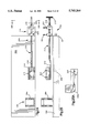
- FIGS. 18-20 illustrate the use of the neck imaging platform as modified for imaging an ankle of a patient (not shown).
- the head panel 32 is modified by the addition of a foot rest 170.
- the foot rest 170 is secured to the panel 32 by suitable means.
- the patient lies on the table 10 with, instead of his head at the head end 22, his feet toward that end.
- the bottom of the patient's foot is positioned against the foot rest 170, with the ankle over the recessed panel 34.
- An ankle imaging coil 172 is placed over the ankle.
- a strap 174 secures the patient's foot to the foot rest 170.
- the patient's ankle When the bladder 162 is in the neutral condition illustrated in FIG. 18, the patient's ankle is in a normal position and may be imaged.
- the panel 32 Upon further inflation of the bladder 162, the panel 32 raises upwardly away from the major side surface 20 of the table 10. The footrest 170 bends the patient's ankle and the ankle may then be imaged with the coil 172 in that bent condition.
- the panel 32 Upon the application of suction or lowering of pressure to the bladder 162 (FIG. 20), the panel 32 is pivoted down below the major side surface 20 of the table 10, thus bending the ankle in the opposite direction. The ankle may be imaged in that opposite direction with the secondary coil 172.
- FIGS. 21-23 illustrate an alternate actuating mechanism for the ankle imaging platform of FIGS. 18-20.
- the actuating mechanism is like the actuating mechanism illustrated in FIGS. 12 and 13 for use of the panel 32 in cervical spine imaging.
- the panel 32 and footrest 170 are pivoted either above the major side surface 20 of the table 10, or below the surface 20, to position the ankle for imaging at any selected position within its range of motion. It should be understood that a separate movable portion of the table 10 could be provided for use in ankle imaging, rather than using the neck imaging platform 30.
- a table in accordance with the present invention need not include every specific movable platform as shown herein. Rather, such a table may include only one movable platform, or any combination of various movable platforms.
- suitable control means is provided for moving the several platforms, in a known manner, in order to provide repeatable movement of the various platforms through their respective ranges of motion, in order to provide repeatable imaging at known positions.
- the table can also be used, of course, for other types of imaging such as ultrasound or CAT scans.
- any of the platforms may be provided as separate devices which can be placed atop a known imaging table, rather than being built into a new table as shown.
- the present invention provides an imaging table for positioning a body part so as to control the position or orientation of the body part.
- This positioning is independently controllable by the operator from a location external to the primary coil.
- This positioning requires no physical support effort by the patient during the time period of the imaging to maintain the selected position, as the table fully supports the weight of the body part connected therewith. Accordingly, a plurality of sequential images may be taken of a joint, for example, in differing positions, without undue effort on the part of the patient.
- FIGS. 24-26 illustrate an apparatus 200 for positioning a body part within a primary imaging coil.
- the apparatus 200 is mounted to an imaging table 202 which may be the imaging table 10 or may be a known imaging table.
- a known secondary imaging coil 204 is secured to the table 202 by suitable means. The coil is located in a position for imaging a particular body part. As illustrated in FIGS. 24 and 25, the coil 204 is positioned to image a shoulder of a patient who is lying on the table 202 with his head adjacent the end 206 of the table 202.
- the apparatus 200 includes a support rod 210 extending longitudinally along the table 202 from a position over the table 202 (inside the primary coil) to a position off the end of the table 202 (outside the coil).
- the rod 210 has an inner end portion 212 to which is fixed an attachment member 214.
- the member 214 may be any suitable structure such as a cuff for attachment to a body part such as a forearm, for example, and may include means such as the straps 215 for securing the cuff to the body part for movement therewith.
- the rod 210 also has an outward end portion 216 to which is attached a handle 218 for rotational and longitudinal movement of the rod 210 by a person other than the patient (not shown).
- the rod 210 extends through and is positioned by an index mechanism 220, better seen in FIG. 26.
- the index mechanism 220 includes a base 222 having a first leg portion 224 and a second leg portion 226.
- the leg portion 224 is fixed to the table 202.
- the leg portion 226 has an upper major side surface 228 to which are attached support blocks 230 and 232.
- the support block 230 has an opening 234 through which the rod 210 extends and is movable.
- the support block 232 has an opening 236, aligned with the opening 234, through which the rod 210 also extends and is movable.
- the blocks 230 and 232 support the rod 210, and thus the cuff 214.
- the block 232 also has a plurality of index openings 238.
- the index openings 238 are spaced regularly in a circle around the rod 210.
- An index block 240 is disposed on the rod 210 outside the block 232.
- the rod 210 extends through an opening 246 in the index block 240.
- the index block 240 includes a split clamp portion 242 and a clamping bolt 244. When the split clamp 242 is loosened, the index block 240 is rotatable on and movable longitudinally on the rod 210. When the split clamp 242 is tightened, the block 240 is fixed for movement with the rod 210.
- the index block 240 has an index pin opening 250 through which is extensible an index pin 252.
- the opening 250 is the same distance from the center of the opening 246, as the index openings 238 are from the center of the opening 236 in the block 232.
- the index pin opening 250 is alignable with any selected one of the index openings 238 on the support block 232.
- the index pin 252 may be inserted through the index pin opening 250 and into the selected index opening 238, to block rotation of the index block 240 relative to the support block 232. If the index block 240 is clamped firmly to the rod 210, this blocks rotational movement of the rod 210 relative to the support block 232.
- the support block 232 Since the support block 232 is fixed to the table 202, this therefore blocks rotational movement of the rod 210 relative to the table 202, also thus fixing the cuff 214 in position. Further, when the index pin 252 is extended through the index pin opening 250 and into one of the index locations 238, the index assembly 220 blocks longitudinal movement of the rod 210 relative to the table 202. Thus, the cuff 214 is completely fixed in position relative to the table 202 and the coil 204.
- the index block 240 may have a spring loaded ball 254 on its radially outer surface facing the support block 232, which is selectively engageable at one of a plurality of ribbed index locations 256, thus functioning as a detent mechanism. This is suitable for a patient-directed operation. If the apparatus 200 is to be patient directed, the portion of the rod 210 extending outwardly past the index mechanism 220 may be omitted. The patient adjusts the index mechanism by moving the body part, thus moving the cuff and support rod. Other index constructions are equally feasible.
- the patient is first placed on the table 202 in a position as desired.
- the coil 204 is adjusted so as to properly image the body part in question. (It should be noted that use of a secondary coil such as the coil 204 is not essential to functioning or use of the apparatus 200.)
- the cuff 214 is then attached to a portion of the patient's body at a location selected to be able to move the body part to be imaged into a plurality of different positions. For example, if a shoulder joint is to be imaged, then the cuff 214 may be attached to the patient's forearm. Movement of the patient's forearm by means of the rod 210 will then cause the shoulder joint to move between a plurality of different positions.
- the cuff 214 may be attached to the patient's leg, for example, the lower leg. Movement of the cuff 214 will cause movement of the hip joint to a plurality of different positions in which it may be sequentially imaged.
- the rod 210 as noted is longitudinally movable by pulling or pushing on the handle 218.
- the cuff 214 thus moves longitudinally also.
- the operator can therefore control the longitudinal position of the cuff 214, and of its attached body part, from a location exterior to the primary coil.
- the rod 210 is also rotatable, by means of the handle 218.
- the operator rotates the handle 218 to position the cuff 214 and its attached body part in the desired orientation for imaging. This rotational position is then locked in by means of the index assembly 220.
- the index assembly 220 may be provided which can be locked in any rotational position within a full circle.
- the shoulder joint for example, is movable in four degrees of freedom (or multiple planes of movement).
- the present invention provides for movement of a positioning apparatus such as the cuff 214 not merely rotationally and longitudinally, but also up and down and sideways.
- the apparatus 200 may be made movable up and down and also sideways relative to the table 202.
- the index blocks 230 and 232 are movable up and down along rods 231 and 233, respectively, which rods are fixed to the base block 222.
- the support rod 210 and cuff 214 can be moved up and down to provide a third degree of movement in addition to the rotation and longitudinal movement available.
- the index assembly 220 has a guide member 235 engaging in a slot 237.
- the index assembly is movable sideways along the table 202 to carry the support rod 210 and the cuff 214 in a fourth degree of movement.
- traction can be applied to a joint being imaged, in order to distract the joint.
- traction can be applied to a joint by pulling outwardly (to the right as viewed in FIG. 24) on the rod 210.
- Such force when applied to the rod 210 acts through the cuff 214 on the joint being imaged.
- Distracting a joint can allow a better view of the parts of the joint and thus an increased imaging benefit. This feature is not available with present imaging apparatus.
- cuffs or clamps in addition to the one cuff shown in the drawings, may be attached to the body to more carefully and tightly control its movement and positioning.
- cuffs may be used, such as inflatable cuffs, etc.
- the cuffs should further be designed so that there is no plastic in contact with the skin. Such Contact causes sweating and perspiration build up which causes imaging aberrations. Accordingly, a material is preferably provided against the skin to wick the perspiration away.
- the present invention provides an apparatus for longitudinally and rotationally positioning a body part so as to control the position or orientation of a joint connected with the body part.
- This positioning is independently controllable by the operator from a location external to the,primary coil.
- This positioning requires no physical support effort by the patient during the time period of the imaging, since the rod positioning apparatus fully supports the weight of the body part connected therewith.
- this adjustable positioner require any effort on the part of the patient to maintain the selected position, as the apparatus 200 performs that function also.
- a plurality of sequential images may be taken of a joint, for example, in differing positions, without undue effort on the part of the patient. (It should be noted that patient control of any of the positioning apparatus of the present invention is possible, as well as the described operator control.)
- FIGS. 27-29 illustrate another body part positioner having two degrees of movement.
- An apparatus 260 includes a saddle 262 having upstanding side portions 264 and 266 joined by a bottom portion 268.
- the saddle 262 is mounted on a base block 270.
- the base block 270 is mounted on a panel 272 which may be the head panel 32 of the table illustrated in FIG. 1A.
- the panel 272 has a plurality of index openings 274.
- An index pin 276 extends through a portion 278 of the base block 270 and is receivable in a selected one of the openings 274.
- the base block 270 is pivotally mounted at 280 to the panel 272.
- the base block 270, with its attached saddle 262 may be positioned at a selected one of a plurality of rotational positions relative to the panel 272, as shown in phantom in FIG. 27.
- An index plate 282 is attached to the saddle 262.
- the index plate 282 and saddle 262 are pivotally mounted at 284 to the base block 270.
- the index plate 282 has a plurality of index openings 286 spaced in an arc about the pivot mounting 284.
- a locator opening (not shown) is located behind the index plate 282, in the base block 270.
- the saddle 262, with its attached index plate 282 may be pivotally rotated about the mounting 284, as shown in phantom in FIG. 28, and secured in a position by insertion of an index pin (not shown) through the selected opening 286 into the locator opening in the base block 270.
- the patient's head is secured in the saddle 262.
- the saddle 262 and base block 270 are then swung around the pivot axis 280 and locked in a selected position with the index openings 274.
- the saddle 262 is also rotated, with the index plate 282, about the pivot axis 284 and locked in a selected position.
- the patient's head or cervical spine is then imaged.
- the apparatus 260 is then adjusted to a different condition, moving the patient's head or spine to a new position.
- the patient's head or spine is then imaged again.
- a patient's head or cervical spine when the head is in the saddle 262, can be selectively positioned in any one of a plurality of different orientations within two separate degrees of motion.
- the head panel 272 is pivotally mounted to the table 10
- the attached saddle 262 may also be moved up and down out of the plane of the table, thus moving the patient's head in the saddle 262 in yet a third degree of motion.
- the control of all these movements may be automated with a fluid drive or other means, may be made remotely controllable from a location outside the coil, or may be patient directed.
- the present invention also provides apparatus for positioning a body part of a patient for imaging in a plurality of different degrees of motion.
- the patient's cervical spine may be imaged in a sequence of images by moving the saddle 262 in the desired direction within the various degrees of motion and locking it in place at each selected position.
- the positioning apparatus 260 does this for him. Accordingly, the imaging process is made significantly more stable and more comfortable for the patient.
- coil support panels such as the recessed panels 34 and 48 (FIG. 1A) are located below the upper major side surface 20 of the table 10, a flat surface coil placed therein will not interfere with normal body positioning. Thus, it is seen that recessing the coils, itself, provides a significant benefit.
- FIGS. 30-40 Several patient directed devices are illustrated in FIGS. 30-40. Such devices can be part of a new imaging table as described above, but can also be independent, that is, add-ons to an existing imaging table (as the apparatus 200 is an add-on to the table 202 in FIGS. 24-26). They are therefore less expensive and more widely usable.
- patient-directed devices can be end-mounted fixtures such as a modification of those shown in FIGS. 24-26. They can also be fixtures mounted to the upper surface of the table, in effect replacing the movable platforms of the table of FIG. 1A.
- FIGS. 30-36 illustrate a patient directed wrist movement apparatus 300.
- the apparatus 300 includes a base 302 which may be secured to an imaging table with suitable means not shown.
- the base 302 supports an imaging coil 304.
- the patient's forearm is placed on a forearm cuff 306 secured to the base 302.
- the patient's hand is placed, thumb up as seen in FIG. 33, in a hand cuff 308.
- the hand cuff 308 is pivotally mounted at 310 to the base 302.
- a detent mender 312 is located on a lower end portion 314 of the hand cuff 308.
- the detent member 312 is engageable with a ratchet-type member 316 on the base 302.
- the hand cuff 308 and the base 302 are releasably interlockable at a plurality of positions within their range of rotational movement.
- the patient simply applies sufficient torque to release the interconnection between the hand cuff 308 and the base 302 and thereby flex or extend his wrist to the next desired position.
- the apparatus 300 then interlocks at this newly selected position for imaging by the coil 304.
- FIG. 32 A modification of the apparatus 300 is illustrated in FIG. 32 with an apparatus 320 having a different hand cuff 322.
- the hand cuff 322 is designed to have the hand lie flat rather than on edge, with the thumb to the side as viewed in FIG. 32.
- the wrist is again movable through its range of motion, this time being imaged in a position 90° from that shown in FIG. 30.
- FIGS. 37-40 illustrate a patient directed knee imaging apparatus 330.
- the apparatus is similar to the knee platform of the table 10 of FIG. 1A, but is instead designed to be patient directed (actuated) rather than technician or operator directed.
- the apparatus 330 includes a base 332.
- the base 332 rests on the upper major side surface of the table. Suitable means may be provided to secure the base 332 to the table.
- a lower leg cuff 334 is releasably secured to the lower leg.
- the cuff 334 is attached at 336 to the base 332 to maintain the same focal point of imaging as the knee is flexed.
- An upper leg cuff 338 is releasably secured to the upper leg.
- the upper leg cuff is also attached at 340 to the base 332.
- a knee imaging coil 342 is fixed for movement with a movable panel or portion 344 of the base 332. Attached to the patient's foot is a footrest 346 with a pawl member 348. The pawl member 348 engages a ratchet portion 350 on the base 332.
- the patient simply bends his knee to move his foot and thus the pawl member 348 along the ratchet portion 350 from one position to the next.
- the panel 344 moves in a manner as described above.
- the patient's foot is then held in that position firmly enough to allow for accurate imaging.
- the secondary coil 342 moves with the knee and generally stays in position relative to the knee.
- the secondary coil 342 is constrained for movement by the panel 344 so that it stays in the proper planar orientation relative to the primary imaging coil (not shown).
- the cuffs 334 and 338 are constrained for proper movement by the mechanisms which attach them to the base 332 in order to maintain the same focal point of imaging as the knee is flexed.
- the coil 342 stays in close proximity to the knee, moves longitudinally and up and down as the knee moves, and maintains its proper planar orientation throughout its range of motion.
- the apparatus 330 is a distraction member 352 (FIG. 40).
- the distraction member 352 is an inflatable bladder having a bellows-type construction for support.
- the bladder 352 extends between the lower leg panel 354 and the lower leg cuff 334. When the bladder is inflated, it applies force to push the lower leg up to stress the knee outwardly. This can be done to check ligaments in the knee for damage or weakness.
- This feature of distraction or stressing of a joint can be applied in other joints, on other positioning apparatus, and to move body parts in an manner needed to simulate natural loading of a joint or to enable better imaging of the joint under various conditions.
- the present invention provides apparatus for use in imaging which can be attached to an existing table, allows the patient to direct the movement, controls the motion of the joint in a repeatable manner, moves a secondary coil with the joint, and holds the secondary coil in proper alignment.
- the movement can be operator controlled, also, by using, for example, a rod attached to the pawl device for moving the patient's foot.
- Similar constructions as modified can be used to provide for patient directed movement of other body parts and joints.
- a joint is small enough and/or limited enough in its range of motion that imaging the joint with one fixed secondary coil provides acceptable resolution, then it may not be necessary to move the secondary coil.
- the wrist is a relatively small joint which, even when moved through its entire range of motion, does not take a large amount of space.
- the wrist is imaged using flat plates on either side of the wrist or a coil extending around the wrist.
- the patient directed apparatus 300 (FIGS. 30-36) for moving the wrist through its range of motion within fixed coils.
- the shoulder is a joint which does not move significantly through space When bent. Accordingly, it can usually be imaged successfully using a fixed coil.
- the present invention provides the fixture 200 (FIGS. 24-26) for moving the shoulder through its range of motion within the fixed coil.
- the present invention provides fixtures for moving the secondary coil with the joint.
- An example is the movable knee platforms of the table of FIG. 1A.
- Another example is the apparatus of FIGS. 37-40 for imaging the knee in a patient directed manner with a moving secondary coil.
- any one of the movable portions of the apparatus shown could be driven by a piston-cylinder device which is pneumatic or hydraulic.
- a pneumatic motor drive could be used, as well as an electric motor drive.
- the pawl and ratchet or detent mechanisms illustrated in FIGS. 30-40 could be used in other configurations, as they are especially suitable for precise, repeatable incremental motion control.
- reproducability of the movement is desirable so that the patient's progress over a period of time can be checked.
- indexing movement of the body part being imaged through degrees or distance is advantageous.
- Reproducability, as provided by the present invention is also useful in conducting clinical studies of groups of patients.
- a known primary MRI coil 360 with a table 362 has a height 361 from the table to the inside of the coil of 16".
- the table 362 has a width 363 of 19".
- a replacement primary MRI coil 364 in accordance with the present invention, with a table 366 has a height 365 from the table to the inside of the coil of 21.5".
- the table has a width 367 of 24".
- an MRI primary coil is mounted to extend vertically rather than horizontally.
- a primary MRI coil 368 extends vertically rather than horizontally.
- a patient may be placed in a standing or seated position on a support 370 for imaging in the coil 368.
- a ram 372 is operable to move the patient into and out of the coil 368.
- Positioning fixtures, etc. are mounted to a support member 374.
- a weight or other tractive force can be attached to the arm to simulate shoulder joint loading experienced when carrying a heavy object.
- the knee can be imaged with the patient standing to see how the joint appears when loaded with body weight.
- the spine can be imaged when standing or seated to check for disc or vertebral problems which are experienced in normal life but which disappear when the patient lies down to be imaged in a known horizontal imaging coil.
- any of the positioning apparatus disclosed herein are usable with or without a secondary coil. When used with a secondary coil, they provide the benefit of constraining movement of the secondary coil in a proper planar orientation relative to the primary coil, and also the benefit of keeping the secondary coil in close proximity to the body part being moved and imaged.
- the various apparatus of the present invention are used for magnetic resonance imaging, they must be made of non-ferromagnetic materials. Plastic is preferred for the table and the positioner, while brass is suitable for mechanical drive mechanisms. Fluid drive mechanisms are also highly suitable because they can be easily constructed using plastic components. Wood is also usable.
Abstract
Description
Claims (12)
Priority Applications (1)
| Application Number | Priority Date | Filing Date | Title |
|---|---|---|---|
| US08/456,817 US5743264A (en) | 1991-12-04 | 1995-06-01 | Method of imaging an ankle of a patient |
Applications Claiming Priority (3)
| Application Number | Priority Date | Filing Date | Title |
|---|---|---|---|
| US07/802,358 US5349956A (en) | 1991-12-04 | 1991-12-04 | Apparatus and method for use in medical imaging |
| US08/221,848 US5577503A (en) | 1991-12-04 | 1994-04-01 | Apparatus and method for use in medical imaging |
| US08/456,817 US5743264A (en) | 1991-12-04 | 1995-06-01 | Method of imaging an ankle of a patient |
Related Parent Applications (1)
| Application Number | Title | Priority Date | Filing Date |
|---|---|---|---|
| US08/221,848 Division US5577503A (en) | 1991-12-04 | 1994-04-01 | Apparatus and method for use in medical imaging |
Publications (1)
| Publication Number | Publication Date |
|---|---|
| US5743264A true US5743264A (en) | 1998-04-28 |
Family
ID=46246507
Family Applications (5)
| Application Number | Title | Priority Date | Filing Date |
|---|---|---|---|
| US07/802,358 Expired - Lifetime US5349956A (en) | 1991-12-04 | 1991-12-04 | Apparatus and method for use in medical imaging |
| US08/221,848 Expired - Lifetime US5577503A (en) | 1991-12-04 | 1994-04-01 | Apparatus and method for use in medical imaging |
| US08/455,074 Expired - Fee Related US6671537B1 (en) | 1991-12-04 | 1995-05-31 | Apparatus and method for use in medical imaging |
| US08/454,694 Expired - Lifetime US5640958A (en) | 1991-12-04 | 1995-05-31 | Method of imaging a patient's cervical spine |
| US08/456,817 Expired - Lifetime US5743264A (en) | 1991-12-04 | 1995-06-01 | Method of imaging an ankle of a patient |
Family Applications Before (4)
| Application Number | Title | Priority Date | Filing Date |
|---|---|---|---|
| US07/802,358 Expired - Lifetime US5349956A (en) | 1991-12-04 | 1991-12-04 | Apparatus and method for use in medical imaging |
| US08/221,848 Expired - Lifetime US5577503A (en) | 1991-12-04 | 1994-04-01 | Apparatus and method for use in medical imaging |
| US08/455,074 Expired - Fee Related US6671537B1 (en) | 1991-12-04 | 1995-05-31 | Apparatus and method for use in medical imaging |
| US08/454,694 Expired - Lifetime US5640958A (en) | 1991-12-04 | 1995-05-31 | Method of imaging a patient's cervical spine |
Country Status (1)
| Country | Link |
|---|---|
| US (5) | US5349956A (en) |
Cited By (56)
| Publication number | Priority date | Publication date | Assignee | Title |
|---|---|---|---|---|
| US5810729A (en) * | 1997-12-30 | 1998-09-22 | General Electric Company Medical Systems | Method for measuring and adding limb angle indicia to MR images |
| US5991651A (en) * | 1997-08-13 | 1999-11-23 | Labarbera; Joseph A. | Compression/traction method for use with imaging machines |
| EP0995397A3 (en) * | 1998-10-05 | 2000-05-03 | Esaote S.p.A. | Diagnostic and/or therapeutic treatment apparatus, particularly for nuclear magnetic resonance imaging |
| WO2001091642A1 (en) * | 2000-06-02 | 2001-12-06 | Rolf Schindler | Positioning aid for tomographic functional examination of the lumbar column |
| WO2001093764A1 (en) * | 2000-06-02 | 2001-12-13 | Rolf Schindler | Positioning aid for use in performing a tomographic functional examination of the cervical spine |
| US6414490B1 (en) | 1992-12-18 | 2002-07-02 | Fonar Corporation | MRI magnet with enhanced patient entry and positioning |
| EP1219240A3 (en) * | 2000-12-21 | 2002-11-27 | Marconi Medical Sytems Finland Inc. | Ligament loading device |
| US6522145B1 (en) | 1992-09-28 | 2003-02-18 | Fonar Corporation | Magnetic resonance imaging with patient positioning and surgery |
| US6538283B1 (en) | 2000-07-07 | 2003-03-25 | Lucent Technologies Inc. | Silicon-on-insulator (SOI) semiconductor structure with additional trench including a conductive layer |
| US20030131855A1 (en) * | 2002-01-17 | 2003-07-17 | Carter Clayton Reed | Device for immobilizing a patient and compressing a patient's skeleton, joints and spine during diagnostic procedures using an MRI unit, CT scan unit or x-ray unit |
| US20030184296A1 (en) * | 2002-04-01 | 2003-10-02 | Ilan Elias | Apparatus for generating a passive movement of a patient in magnetic resonance tomograph |
| US20030190067A1 (en) * | 2002-04-03 | 2003-10-09 | Osamu Tsujii | Apparatus, method, program, and system for displaying motion image, apparatus, method, program, and system for processing motion image, computer-readable storage medium, and method and system for assisting image diagnosis |
| US20030204136A1 (en) * | 2002-04-25 | 2003-10-30 | Fonar Corporation | Magnetic resonance imaging fixture mounting |
| US6668184B1 (en) * | 2000-12-19 | 2003-12-23 | Ge Medical Systems Global Technology Company, Llc | System for and method of synchronizing an image data receiver and an MR imaging acquisition slice |
| US20040030241A1 (en) * | 2002-04-25 | 2004-02-12 | Fonar Corporation | Magnetic resonance imaging fixture mounting |
| WO2004047640A1 (en) * | 2002-11-25 | 2004-06-10 | Fonar Corporation | Method, apparatus, and facility for mri dual scanning |
| US6750653B1 (en) * | 2001-04-03 | 2004-06-15 | Usa Instruments, Inc. | Knee/foot/ankle combination coil for MRI systems |
| US20040133097A1 (en) * | 1991-12-04 | 2004-07-08 | Bonutti Peter M. | Apparatus and method for use in medical imaging |
| US20040186374A1 (en) * | 2003-03-18 | 2004-09-23 | Luigi Satragno | Magnetic resonance imaging apparatus |
| US6828792B1 (en) | 1999-11-24 | 2004-12-07 | Fonar Corporation | MRI apparatus and method for imaging |
| US20050222505A1 (en) * | 2001-06-21 | 2005-10-06 | Fonar Corporation | MRI scanner and method for modular patient handling |
| WO2005102173A1 (en) * | 2004-04-27 | 2005-11-03 | Ilan Elias | Diagnostic apparatus |
| US20050248347A1 (en) * | 2000-07-28 | 2005-11-10 | Fonar Corporation | Stand-up vertical field MRI apparatus |
| US6969193B1 (en) | 2002-11-12 | 2005-11-29 | Modern Way Immobilizers, Inc. | Foot immobilizer |
| US20060002600A1 (en) * | 2004-07-01 | 2006-01-05 | Johanne Martel-Pelletier | Non-invasive joint evaluation |
| US20060135959A1 (en) * | 2004-03-22 | 2006-06-22 | Disc Dynamics, Inc. | Nuclectomy method and apparatus |
| US20060161087A1 (en) * | 2005-01-17 | 2006-07-20 | Portal, Inc. | Spinal compression system and methods of use |
| US20060224974A1 (en) * | 2005-04-01 | 2006-10-05 | Paul Albrecht | Method of creating graphical application interface with a browser |
| US7123008B1 (en) | 2002-04-19 | 2006-10-17 | Fonar Corporation | Positional magnetic resonance imaging |
| US7127802B1 (en) | 1997-11-21 | 2006-10-31 | Fonar Corporation | Method of fabricating a composite plate |
| US20060245539A1 (en) * | 2005-05-02 | 2006-11-02 | Predrag Sukovic | CT scanner for lower extremities |
| US20060253198A1 (en) * | 2005-05-03 | 2006-11-09 | Disc Dynamics, Inc. | Multi-lumen mold for intervertebral prosthesis and method of using same |
| US20070043287A1 (en) * | 2003-09-08 | 2007-02-22 | Degraaf Frits A | Retrospective triggered mri of active or passive joint motion |
| EP1640737A3 (en) * | 1999-11-01 | 2007-04-18 | Arthrovision, Inc. | Evaluating disease progression using magnetic resonance imaging |
| US7239906B1 (en) | 2002-04-18 | 2007-07-03 | Fonar Corporation | Magnetic resonance imaging system including a transpolar fixture |
| US20070282192A1 (en) * | 2004-04-07 | 2007-12-06 | Esaote S.P.A. | Patient Support Device,Such as a Patient Bed, Table or Chair for Use with Magnetic Resonance Imaging Apparatuses |
| US20070285093A1 (en) * | 2006-06-12 | 2007-12-13 | Daniel Driemel | Head coil arrangement with an adjustable neck-engaging portion for use in a magnetic resonance apparatus |
| WO2008064398A1 (en) * | 2006-11-28 | 2008-06-05 | Orthonova Pty Ltd | Diagnostic system |
| US20080221421A1 (en) * | 2007-03-09 | 2008-09-11 | Korea Advanced Institute Of Science And Technology | Apparatus for measuring perfusion rate of legs |
| US20090025732A1 (en) * | 2002-04-01 | 2009-01-29 | Ilan Elias | Method and device for generating a passive movement in a diagnostic device |
| US20090076518A1 (en) * | 2004-03-22 | 2009-03-19 | Disc Dynamics, Inc. | Method and system for stabilizing adjacent vertebrae |
| US20090088848A1 (en) * | 2004-12-16 | 2009-04-02 | Martz Erik O | Instrument set and method for performing spinal nuclectomy |
| US20090318795A1 (en) * | 2008-06-19 | 2009-12-24 | Rossi Remo J | Imaging table with replaceable support parts |
| US7697971B1 (en) | 2000-07-28 | 2010-04-13 | Fonar Corporation | Positioning system for an MRI |
| US7701209B1 (en) | 2001-10-05 | 2010-04-20 | Fonar Corporation | Coils for horizontal field magnetic resonance imaging |
| US7706858B1 (en) | 2003-05-09 | 2010-04-27 | Fonar Corporation | Head and neck immobilization in magnetic resonance imaging |
| US7740016B1 (en) | 2005-06-28 | 2010-06-22 | Modern Way Immobilizers, Inc. | Ankle and foot immobilizer |
| US7906966B1 (en) | 2001-10-05 | 2011-03-15 | Fonar Corporation | Quadrature foot coil antenna for magnetic resonance imaging |
| US8036730B1 (en) | 2002-04-19 | 2011-10-11 | Fonar Corporation | Temporal magnetic resonance imaging |
| US8055325B1 (en) | 2006-01-10 | 2011-11-08 | Fonar Corporation | Seated patient support and use thereof in magnetic resonance imaging |
| US8401615B1 (en) | 2004-11-12 | 2013-03-19 | Fonar Corporation | Planar coil flexion fixture for magnetic resonance imaging and use thereof |
| US8599215B1 (en) | 2008-05-07 | 2013-12-03 | Fonar Corporation | Method, apparatus and system for joining image volume data |
| US9386939B1 (en) | 2007-05-10 | 2016-07-12 | Fonar Corporation | Magnetic resonance imaging of the spine to detect scoliosis |
| US9766310B1 (en) | 2013-03-13 | 2017-09-19 | Fonar Corporation | Method and apparatus for magnetic resonance imaging of the cranio-cervical junction |
| US10485720B2 (en) | 2012-09-18 | 2019-11-26 | Medacta International Sa | Apparatus for positioning the lower limb of a patient during operation, in particular for hip replacement operations with anterior approach, and surgical positioning system comprising said apparatus |
| US11013476B1 (en) | 2020-06-08 | 2021-05-25 | SIMULATE Technologies, LLC | Weightbearing simulation assembly and methods of using the same to image a subject |
Families Citing this family (127)
| Publication number | Priority date | Publication date | Assignee | Title |
|---|---|---|---|---|
| US5542423A (en) * | 1991-12-04 | 1996-08-06 | Apogee Medical Products, Inc. | Indexing assembly for joint imaging |
| US5724970A (en) * | 1993-04-06 | 1998-03-10 | Fonar Corporation | Multipositional MRI for kinematic studies of movable joints |
| DE4329922A1 (en) * | 1993-09-04 | 1995-03-09 | Philips Patentverwaltung | MR imaging method and arrangement for carrying out the method |
| US5709649A (en) * | 1993-09-13 | 1998-01-20 | Glacier Cross, Inc. | Neck curvature alignment device |
| US5515863A (en) * | 1994-01-07 | 1996-05-14 | Fonar Corporation | Gastrointestinal magnetic resonance imaging |
| DE4441046C2 (en) * | 1994-11-18 | 2000-05-18 | Siemens Ag | Movable positioning aid for the kinematic examination of abduction and rotation of the shoulder joint |
| US5807255A (en) * | 1994-12-21 | 1998-09-15 | Resonex Development, Ltd. | Positioning device for producing controlled movement of the cervical spine |
| US5735278A (en) * | 1996-03-15 | 1998-04-07 | National Research Council Of Canada | Surgical procedure with magnetic resonance imaging |
| US5680861A (en) * | 1996-07-08 | 1997-10-28 | General Electric Company | Modular subject positioning system for medical imaging |
| US5848979A (en) * | 1996-07-18 | 1998-12-15 | Peter M. Bonutti | Orthosis |
| US5718717A (en) | 1996-08-19 | 1998-02-17 | Bonutti; Peter M. | Suture anchor |
| US5758647A (en) * | 1996-10-17 | 1998-06-02 | Cummins; Jimmie E. | Support and indexing apparatus for lumbar region imaging |
| JP2000506768A (en) * | 1996-12-18 | 2000-06-06 | コーニンクレッカ フィリップス エレクトロニクス エヌ ヴィ | MR method for imaging of joined moving parts |
| AT2458U1 (en) * | 1997-04-18 | 1998-11-25 | Zembsch Alexander Dr | DEVICE FOR THE DEFINED GUIDANCE OF EXTREMITIES FOR THE FUNCTIONAL DIAGNOSTICS OF MOVEMENT OF EXTREMITY JOINTS, ESPECIALLY OF KNEE JOINTS, BY MEANS OF MAGNETIC RESONANCE TOMOGRAPHY |
| AT405126B (en) * | 1997-07-10 | 1999-05-25 | Graf Reinhard | COORDINATE GUIDE SYSTEM AND REFERENCE POSITIONING SYSTEM |
| US6045551A (en) | 1998-02-06 | 2000-04-04 | Bonutti; Peter M. | Bone suture |
| US6711430B1 (en) | 1998-10-09 | 2004-03-23 | Insight Neuroimaging Systems, Inc. | Method and apparatus for performing neuroimaging |
| US6873156B2 (en) * | 1998-05-06 | 2005-03-29 | Insight Neuroimaging Systems, Llc | Method and apparatus for performing neuroimaging |
| US6113562A (en) | 1998-06-01 | 2000-09-05 | Peter M. Bonutti | Shoulder orthosis |
| DE19933802B4 (en) * | 1999-07-16 | 2004-04-22 | Siemens Ag | storage device |
| US6447516B1 (en) | 1999-08-09 | 2002-09-10 | Peter M. Bonutti | Method of securing tissue |
| US6368343B1 (en) | 2000-03-13 | 2002-04-09 | Peter M. Bonutti | Method of using ultrasonic vibration to secure body tissue |
| DE19940778B4 (en) * | 1999-08-27 | 2005-12-22 | Bruker Biospin Mri Gmbh | Apparatus for performing nuclear magnetic resonance measurements on a body part of a large animal |
| US6635073B2 (en) | 2000-05-03 | 2003-10-21 | Peter M. Bonutti | Method of securing body tissue |
| US9138222B2 (en) | 2000-03-13 | 2015-09-22 | P Tech, Llc | Method and device for securing body tissue |
| US8932330B2 (en) | 2000-03-13 | 2015-01-13 | P Tech, Llc | Method and device for securing body tissue |
| US7094251B2 (en) | 2002-08-27 | 2006-08-22 | Marctec, Llc. | Apparatus and method for securing a suture |
| EP1276432B1 (en) * | 2000-04-20 | 2007-02-14 | Koninklijke Philips Electronics N.V. | Head support for interventional mr |
| US6904630B2 (en) * | 2000-07-21 | 2005-06-14 | Siemens Medical Solutions Usa, Inc. | Tabletop for radiation therapy and diagnostic imaging |
| US6895616B2 (en) * | 2000-07-27 | 2005-05-24 | Hill-Rom Services, Inc. | Epidural patient support |
| US6502577B1 (en) | 2000-09-18 | 2003-01-07 | Peter M. Bonutti | Method for moving finger joints |
| US6503213B2 (en) | 2000-12-01 | 2003-01-07 | Peter M. Bonutti | Method of using a neck brace |
| US6575926B2 (en) | 2000-12-15 | 2003-06-10 | Bonutti 2003 Trust-A | Myofascial strap |
| WO2002064194A1 (en) * | 2001-02-14 | 2002-08-22 | Acist Medical Systems, Inc. | Fluid injector system |
| DE10114013B4 (en) * | 2001-03-22 | 2005-06-23 | Siemens Ag | magnetic resonance system |
| US6907629B2 (en) * | 2001-07-13 | 2005-06-21 | Diacor, Inc. | Diagnostic imaging tabletop |
| US6754520B2 (en) * | 2001-10-19 | 2004-06-22 | Koninklijke Philips Electronics N.V. | Multimodality medical imaging system and method with patient handling assembly |
| US7254438B2 (en) * | 2001-10-19 | 2007-08-07 | Koninklijke Philips Electronics N.V. | Multimodality medical imaging system and method with intervening patient access area |
| US6961606B2 (en) * | 2001-10-19 | 2005-11-01 | Koninklijke Philips Electronics N.V. | Multimodality medical imaging system and method with separable detector devices |
| US7680525B1 (en) * | 2001-11-26 | 2010-03-16 | Fonar Corporation | Method for lateral motion magnetic resonance imaging |
| US6719765B2 (en) | 2001-12-03 | 2004-04-13 | Bonutti 2003 Trust-A | Magnetic suturing system and method |
| US9155544B2 (en) | 2002-03-20 | 2015-10-13 | P Tech, Llc | Robotic systems and methods |
| US7103930B1 (en) * | 2002-03-21 | 2006-09-12 | The Trustees Of Columbia University | Device for the calibration and standardization of hip rotation |
| US7218766B2 (en) * | 2002-04-15 | 2007-05-15 | General Electric Company | Computer aided detection (CAD) for 3D digital mammography |
| US6948502B2 (en) * | 2002-05-09 | 2005-09-27 | Mayo Foundation For Medical Education And Research | Method and apparatus for positioning a forearm for imaging and analysis |
| DE10229490B3 (en) * | 2002-07-01 | 2004-02-05 | Siemens Ag | Magnetic resonance imaging device for medical imaging has driven patient table coupled to gradient coil unit for common movement into imaging space |
| ES2277087T3 (en) * | 2002-07-09 | 2007-07-01 | Aecc Enterprises Limited | METHOD FOR REPRESENTATION WITH IMAGES THE RELATIVE MOVEMENT OF SKELETAL SEGMENTS. |
| US6704957B2 (en) * | 2002-07-31 | 2004-03-16 | Steven L. Rhodes | Patient support pad for medical imaging equipment |
| CA2633137C (en) * | 2002-08-13 | 2012-10-23 | The Governors Of The University Of Calgary | Microsurgical robot system |
| US7063461B2 (en) * | 2002-11-21 | 2006-06-20 | Qfix Systems, Llc | Patient support device with shoulder depression device |
| US20040133980A1 (en) * | 2003-01-15 | 2004-07-15 | Coppens Daniel D. | Indexing positioning system for accurate and repetitive positioning of patients in a multimodal environment |
| US20040199072A1 (en) * | 2003-04-01 | 2004-10-07 | Stacy Sprouse | Integrated electromagnetic navigation and patient positioning device |
| US7343194B2 (en) * | 2003-04-08 | 2008-03-11 | Insight Neuroimaging Systems, Llc | Method and apparatus for performing neuroimaging |
| US20040215074A1 (en) * | 2003-04-24 | 2004-10-28 | Vincenzo Giuliano | Imaging and scoring method for cervical spinal impairment using magnetic resonance imaging |
| US7497864B2 (en) | 2003-04-30 | 2009-03-03 | Marctec, Llc. | Tissue fastener and methods for using same |
| US7836890B2 (en) * | 2003-10-17 | 2010-11-23 | Diacor, Inc. | Systems for immobilization of a patient for diagnosis and treatment of breast tissue |
| US7030612B1 (en) * | 2004-01-13 | 2006-04-18 | Fonar Corporation | Body rest for magnetic resonance imaging |
| US8066656B2 (en) | 2005-10-28 | 2011-11-29 | Bonutti Research, Inc. | Range of motion device |
| US7452342B2 (en) | 2004-03-08 | 2008-11-18 | Bonutti Research Inc. | Range of motion device |
| US20080039873A1 (en) | 2004-03-09 | 2008-02-14 | Marctec, Llc. | Method and device for securing body tissue |
| EP1792280A1 (en) * | 2004-09-09 | 2007-06-06 | Koninklijke Philips Electronics N.V. | System for the three-dimensional imaging of a moving joint |
| WO2006036946A2 (en) * | 2004-09-27 | 2006-04-06 | Fonar Corporation | Magnetic resonance imaging system, apparatus and associated methods |
| DE102004050385B4 (en) * | 2004-10-15 | 2006-11-16 | Siemens Ag | patient table |
| US20060089646A1 (en) | 2004-10-26 | 2006-04-27 | Bonutti Peter M | Devices and methods for stabilizing tissue and implants |
| US9463012B2 (en) | 2004-10-26 | 2016-10-11 | P Tech, Llc | Apparatus for guiding and positioning an implant |
| US9271766B2 (en) | 2004-10-26 | 2016-03-01 | P Tech, Llc | Devices and methods for stabilizing tissue and implants |
| US9173647B2 (en) | 2004-10-26 | 2015-11-03 | P Tech, Llc | Tissue fixation system |
| US9089323B2 (en) | 2005-02-22 | 2015-07-28 | P Tech, Llc | Device and method for securing body tissue |
| US7556607B2 (en) * | 2005-04-29 | 2009-07-07 | Warsaw Orthopedic, Inc. | Devices and techniques relating to range of motion of the cervical spine |
| JP4734031B2 (en) * | 2005-05-27 | 2011-07-27 | 株式会社東芝 | MRI equipment |
| US8012108B2 (en) | 2005-08-12 | 2011-09-06 | Bonutti Research, Inc. | Range of motion system and method |
| US7466130B1 (en) | 2006-02-03 | 2008-12-16 | Fonar Corporation | Phased array shoulder coil |
| US7967820B2 (en) | 2006-02-07 | 2011-06-28 | P Tech, Llc. | Methods and devices for trauma welding |
| US11278331B2 (en) | 2006-02-07 | 2022-03-22 | P Tech Llc | Method and devices for intracorporeal bonding of implants with thermal energy |
| US11253296B2 (en) | 2006-02-07 | 2022-02-22 | P Tech, Llc | Methods and devices for intracorporeal bonding of implants with thermal energy |
| US8496657B2 (en) | 2006-02-07 | 2013-07-30 | P Tech, Llc. | Methods for utilizing vibratory energy to weld, stake and/or remove implants |
| US8676293B2 (en) * | 2006-04-13 | 2014-03-18 | Aecc Enterprises Ltd. | Devices, systems and methods for measuring and evaluating the motion and function of joint structures and associated muscles, determining suitability for orthopedic intervention, and evaluating efficacy of orthopedic intervention |
| US11246638B2 (en) | 2006-05-03 | 2022-02-15 | P Tech, Llc | Methods and devices for utilizing bondable materials |
| US20080039714A1 (en) * | 2006-08-08 | 2008-02-14 | Intermagnetics General Corporation | Magnetic resonance imaging system, a gradient coil, and a method of using the system |
| US20080125641A1 (en) * | 2006-08-08 | 2008-05-29 | Intermagnetics General Corporation | Seat, a chair including a seat, and a method of using a magnetic resonance imaging system including a seat |
| US8401612B1 (en) | 2006-09-11 | 2013-03-19 | Fonar Corporation | Magnetic resonance imaging system and method for detecting chiari malformations |
| US7412737B2 (en) * | 2006-09-18 | 2008-08-19 | Encuenta Designs, L.L.C. | Inclined infant sleeper |
| US8641660B2 (en) * | 2006-10-04 | 2014-02-04 | P Tech, Llc | Methods and devices for controlling biologic microenvironments |
| EP1913869A3 (en) * | 2006-10-19 | 2008-12-10 | Esaote S.p.A. | Diagnostic imaging method and apparatus for the anatomical region of the pelvic floor |
| US7846080B2 (en) * | 2007-01-12 | 2010-12-07 | Boren John P | Machine and method for head, neck and, shoulder stretching |
| CA2677333A1 (en) | 2007-02-05 | 2008-08-14 | Bonutti Research Inc. | Knee orthosis |
| US8617185B2 (en) | 2007-02-13 | 2013-12-31 | P Tech, Llc. | Fixation device |
| WO2008116203A2 (en) | 2007-03-22 | 2008-09-25 | Marctec, Llc | Methods and devices for intracorporeal bonding or interlocking of implants with thermal energy |
| US9289270B2 (en) | 2007-04-24 | 2016-03-22 | Medtronic, Inc. | Method and apparatus for performing a navigated procedure |
| US20090012509A1 (en) * | 2007-04-24 | 2009-01-08 | Medtronic, Inc. | Navigated Soft Tissue Penetrating Laser System |
| US8311611B2 (en) * | 2007-04-24 | 2012-11-13 | Medtronic, Inc. | Method for performing multiple registrations in a navigated procedure |
| US8108025B2 (en) * | 2007-04-24 | 2012-01-31 | Medtronic, Inc. | Flexible array for use in navigated surgery |
| US8734466B2 (en) * | 2007-04-25 | 2014-05-27 | Medtronic, Inc. | Method and apparatus for controlled insertion and withdrawal of electrodes |
| US8301226B2 (en) | 2007-04-24 | 2012-10-30 | Medtronic, Inc. | Method and apparatus for performing a navigated procedure |
| US8273043B2 (en) | 2007-07-25 | 2012-09-25 | Bonutti Research, Inc. | Orthosis apparatus and method of using an orthosis apparatus |
| CA2698057A1 (en) | 2007-08-30 | 2009-03-05 | P Tech, Llc | Methods and devices for utilizing thermal energy to bond, stake and/or remove implants |
| US20090099481A1 (en) | 2007-10-10 | 2009-04-16 | Adam Deitz | Devices, Systems and Methods for Measuring and Evaluating the Motion and Function of Joints and Associated Muscles |
| US8905950B2 (en) | 2008-03-04 | 2014-12-09 | Bonutti Research, Inc. | Shoulder ROM orthosis |
| US8584280B2 (en) * | 2008-11-18 | 2013-11-19 | Mercy Medical Research Institute | Pediatric craniofacial surgical table |
| US20110257513A1 (en) * | 2008-11-24 | 2011-10-20 | Micromri, Inc. | Immobilization apparatus for medical imaging |
| WO2010099222A1 (en) | 2009-02-24 | 2010-09-02 | P Tech, Llc | Methods and devices for utilizing bondable materials |
| US20110030698A1 (en) * | 2009-08-06 | 2011-02-10 | Kaufman Kenton R | Mri compatible knee positioning device |
| US9138163B2 (en) | 2009-09-25 | 2015-09-22 | Ortho Kinematics, Inc. | Systems and devices for an integrated imaging system with real-time feedback loop and methods therefor |
| US8732879B2 (en) * | 2010-02-15 | 2014-05-27 | Worldwide Innovations & Technologies, Inc. | Patient support device |
| US8235877B2 (en) * | 2010-03-05 | 2012-08-07 | Boren John P | Apparatus and method of gravity-assisted spinal stretching |
| PT105144A (en) | 2010-06-04 | 2012-09-10 | Fjr Sgps S A | APPARATUS FOR MEASURING THE LAXITY OF THE KNEE |
| WO2012012405A1 (en) * | 2010-07-19 | 2012-01-26 | Patient Transfer Systems, Inc. | Patient support device with lower extremity raiser |
| EP2651295A4 (en) | 2010-12-13 | 2015-11-18 | Ortho Kinematics Inc | Methods, systems and devices for clinical data reporting and surgical navigation |
| DE102011007041B4 (en) * | 2011-04-08 | 2016-07-21 | Siemens Healthcare Gmbh | Receiving device for a joint of a human |
| US20140081659A1 (en) | 2012-09-17 | 2014-03-20 | Depuy Orthopaedics, Inc. | Systems and methods for surgical and interventional planning, support, post-operative follow-up, and functional recovery tracking |
| ITMI20121546A1 (en) | 2012-09-18 | 2014-03-19 | Medacta Int Sa | ADAPTER FLOOR FOR SURGICAL TABLE, IN PARTICULAR FOR REPLACEMENT OPERATIONS OF THE HOOK WITH FRONT APPROACH |
| US10076377B2 (en) | 2013-01-05 | 2018-09-18 | P Tech, Llc | Fixation systems and methods |
| US9402759B2 (en) | 2013-02-05 | 2016-08-02 | Bonutti Research, Inc. | Cervical traction systems and method |
| US9854991B2 (en) | 2013-03-15 | 2018-01-02 | Medtronic Navigation, Inc. | Integrated navigation array |
| WO2014192892A1 (en) * | 2013-05-29 | 2014-12-04 | 株式会社東芝 | Bed device, x-ray ct deviec and medical image diagnostic device |
| US10595744B2 (en) * | 2014-02-14 | 2020-03-24 | MRI Interventions, Inc. | Surgical tool-positioning devices and related methods |
| US10470957B1 (en) * | 2015-04-24 | 2019-11-12 | Carl Denis | Positioning device for beam radiation treatment and imaging |
| US20160354161A1 (en) | 2015-06-05 | 2016-12-08 | Ortho Kinematics, Inc. | Methods for data processing for intra-operative navigation systems |
| US10058393B2 (en) | 2015-10-21 | 2018-08-28 | P Tech, Llc | Systems and methods for navigation and visualization |
| US20170112455A1 (en) * | 2015-10-21 | 2017-04-27 | General Electric Company | Deflection compensating mechanism for medical imaging |
| DE102016211720A1 (en) * | 2016-06-29 | 2018-01-04 | Siemens Healthcare Gmbh | Method for positioning a positionable table |
| US11707203B2 (en) | 2016-10-11 | 2023-07-25 | Wenzel Spine, Inc. | Systems for generating image-based measurements during diagnosis |
| CN106580323A (en) * | 2016-11-14 | 2017-04-26 | 深圳市晓控通信科技有限公司 | Efficient load or traction device used for magnetic resonance imaging |
| US10646173B2 (en) * | 2017-09-05 | 2020-05-12 | General Electric Company | Pediatric support system and method for medical imaging |
| CN111220936B (en) * | 2018-11-23 | 2023-05-26 | 西门子(深圳)磁共振有限公司 | Ankle coil |
| US11525876B2 (en) * | 2019-12-26 | 2022-12-13 | Canon Medical Systems Corporation | Couch and magnetic resonance imaging device |
| EP4044958A1 (en) | 2020-01-31 | 2022-08-24 | ClearPoint Neuro, Inc. | Surgical tool support systems including elongate support legs with adjustable lengths and related methods |
Citations (24)
| Publication number | Priority date | Publication date | Assignee | Title |
|---|---|---|---|---|
| US1239146A (en) * | 1914-02-16 | 1917-09-04 | Victor Electric Corp | X-ray table. |
| US2801142A (en) * | 1954-11-29 | 1957-07-30 | Jesse R Adams | Limb support for operating tables |
| US2972505A (en) * | 1959-09-16 | 1961-02-21 | Ritter Co Inc | Arm rest for surgical tables |
| US3025397A (en) * | 1959-06-11 | 1962-03-13 | Travis | Skull radiography apparatus |
| US3124328A (en) * | 1964-03-10 | kortsch | ||
| US3521876A (en) * | 1967-12-29 | 1970-07-28 | Jeffrey P Smith | Body member support for x-ray examination |
| US3528413A (en) * | 1968-01-23 | 1970-09-15 | Marion L Aydt | Limb support |
| US3766384A (en) * | 1971-04-28 | 1973-10-16 | Tower Co Inc | Surgical table |
| US4050355A (en) * | 1976-08-16 | 1977-09-27 | Kennametal Inc. | Indexing device |
| US4232681A (en) * | 1978-05-16 | 1980-11-11 | Olaf Tulaszewski | Leg positioning device for X-ray filming |
| US4256112A (en) * | 1979-02-12 | 1981-03-17 | David Kopf Instruments | Head positioner |
| US4291229A (en) * | 1979-12-10 | 1981-09-22 | Patt Kenneth W | Support and restraining device for arthographic examination of the knees |
| US4323080A (en) * | 1980-06-23 | 1982-04-06 | Melhart Albert H | Ankle stress machine |
| US4407277A (en) * | 1980-10-27 | 1983-10-04 | Ellison Arthur E | Surgical apparatus |
| US4562588A (en) * | 1981-11-20 | 1985-12-31 | Hermann Ruf | Positioning device for an extension and repositioning apparatus |
| US4616814A (en) * | 1983-07-22 | 1986-10-14 | The Hospital For Sick Children | X-ray head holder |
| US4681308A (en) * | 1985-07-16 | 1987-07-21 | Paul Rice | Diagnostic patient support apparatus |
| US4717133A (en) * | 1984-07-13 | 1988-01-05 | Unisearch Limited | Leg holding and positioning device |
| US4827496A (en) * | 1986-06-23 | 1989-05-02 | M. C. Johnson Co., Inc. | Leg and ankle holder for assisting medical and radiological professionals in X-ray examination and filming of the ankle and foot structure |
| US5001739A (en) * | 1988-06-06 | 1991-03-19 | Fischer William B | Contoured surgical table |
| US5007912A (en) * | 1990-05-30 | 1991-04-16 | Albrektsson Bjoern | Arrangement for fixing a knee-joint in defined positions and for positional control of instruments for replacing the knee-joint with a prosthesis |
| US5078140A (en) * | 1986-05-08 | 1992-01-07 | Kwoh Yik S | Imaging device - aided robotic stereotaxis system |
| US5154178A (en) * | 1990-10-09 | 1992-10-13 | Sri International | Method and apparatus for obtaining in-vivo nmr data from a moving subject |
| US5305750A (en) * | 1990-06-19 | 1994-04-26 | Kabushiki Kaisha Toshiba | Neck bending apparatus |
Family Cites Families (3)
| Publication number | Priority date | Publication date | Assignee | Title |
|---|---|---|---|---|
| US5275174B1 (en) * | 1985-10-30 | 1998-08-04 | Jonathan A Cook | Repetitive strain injury assessment |
| US4791372A (en) * | 1987-08-17 | 1988-12-13 | Resonex, Inc. | Conformable head or body coil assembly for magnetic imaging apparatus |
| US5001793A (en) * | 1990-05-30 | 1991-03-26 | Lui Yui Ching | Vertically actuated array of mattress valves |
-
1991
- 1991-12-04 US US07/802,358 patent/US5349956A/en not_active Expired - Lifetime
-
1994
- 1994-04-01 US US08/221,848 patent/US5577503A/en not_active Expired - Lifetime
-
1995
- 1995-05-31 US US08/455,074 patent/US6671537B1/en not_active Expired - Fee Related
- 1995-05-31 US US08/454,694 patent/US5640958A/en not_active Expired - Lifetime
- 1995-06-01 US US08/456,817 patent/US5743264A/en not_active Expired - Lifetime
Patent Citations (24)
| Publication number | Priority date | Publication date | Assignee | Title |
|---|---|---|---|---|
| US3124328A (en) * | 1964-03-10 | kortsch | ||
| US1239146A (en) * | 1914-02-16 | 1917-09-04 | Victor Electric Corp | X-ray table. |
| US2801142A (en) * | 1954-11-29 | 1957-07-30 | Jesse R Adams | Limb support for operating tables |
| US3025397A (en) * | 1959-06-11 | 1962-03-13 | Travis | Skull radiography apparatus |
| US2972505A (en) * | 1959-09-16 | 1961-02-21 | Ritter Co Inc | Arm rest for surgical tables |
| US3521876A (en) * | 1967-12-29 | 1970-07-28 | Jeffrey P Smith | Body member support for x-ray examination |
| US3528413A (en) * | 1968-01-23 | 1970-09-15 | Marion L Aydt | Limb support |
| US3766384A (en) * | 1971-04-28 | 1973-10-16 | Tower Co Inc | Surgical table |
| US4050355A (en) * | 1976-08-16 | 1977-09-27 | Kennametal Inc. | Indexing device |
| US4232681A (en) * | 1978-05-16 | 1980-11-11 | Olaf Tulaszewski | Leg positioning device for X-ray filming |
| US4256112A (en) * | 1979-02-12 | 1981-03-17 | David Kopf Instruments | Head positioner |
| US4291229A (en) * | 1979-12-10 | 1981-09-22 | Patt Kenneth W | Support and restraining device for arthographic examination of the knees |
| US4323080A (en) * | 1980-06-23 | 1982-04-06 | Melhart Albert H | Ankle stress machine |
| US4407277A (en) * | 1980-10-27 | 1983-10-04 | Ellison Arthur E | Surgical apparatus |
| US4562588A (en) * | 1981-11-20 | 1985-12-31 | Hermann Ruf | Positioning device for an extension and repositioning apparatus |
| US4616814A (en) * | 1983-07-22 | 1986-10-14 | The Hospital For Sick Children | X-ray head holder |
| US4717133A (en) * | 1984-07-13 | 1988-01-05 | Unisearch Limited | Leg holding and positioning device |
| US4681308A (en) * | 1985-07-16 | 1987-07-21 | Paul Rice | Diagnostic patient support apparatus |
| US5078140A (en) * | 1986-05-08 | 1992-01-07 | Kwoh Yik S | Imaging device - aided robotic stereotaxis system |
| US4827496A (en) * | 1986-06-23 | 1989-05-02 | M. C. Johnson Co., Inc. | Leg and ankle holder for assisting medical and radiological professionals in X-ray examination and filming of the ankle and foot structure |
| US5001739A (en) * | 1988-06-06 | 1991-03-19 | Fischer William B | Contoured surgical table |
| US5007912A (en) * | 1990-05-30 | 1991-04-16 | Albrektsson Bjoern | Arrangement for fixing a knee-joint in defined positions and for positional control of instruments for replacing the knee-joint with a prosthesis |
| US5305750A (en) * | 1990-06-19 | 1994-04-26 | Kabushiki Kaisha Toshiba | Neck bending apparatus |
| US5154178A (en) * | 1990-10-09 | 1992-10-13 | Sri International | Method and apparatus for obtaining in-vivo nmr data from a moving subject |
Non-Patent Citations (2)
| Title |
|---|
| "Patellofemoral Joint Abnormalities in Athletes: Evaluation by Kinematic Magnetic Resonance Imaging" by Frank G. Shellock, PhD. published in vol. 3; Issue 4; 1991 of Topics in Magnetic Resonance Imaging, pp. 71-95. |
| Patellofemoral Joint Abnormalities in Athletes: Evaluation by Kinematic Magnetic Resonance Imaging by Frank G. Shellock, PhD. published in vol. 3; Issue 4; 1991 of Topics in Magnetic Resonance Imaging, pp. 71 95. * |
Cited By (95)
| Publication number | Priority date | Publication date | Assignee | Title |
|---|---|---|---|---|
| US20040220467A1 (en) * | 1991-12-04 | 2004-11-04 | Bonutti Peter M. | Patient support apparatus |
| US7328055B2 (en) | 1991-12-04 | 2008-02-05 | Marctec, Llc | Patient support apparatus |
| US6882877B2 (en) | 1991-12-04 | 2005-04-19 | Bonutti Research, Inc. | Magnetic resonance imaging system and method |
| US20040133097A1 (en) * | 1991-12-04 | 2004-07-08 | Bonutti Peter M. | Apparatus and method for use in medical imaging |
| US6522145B1 (en) | 1992-09-28 | 2003-02-18 | Fonar Corporation | Magnetic resonance imaging with patient positioning and surgery |
| US6414490B1 (en) | 1992-12-18 | 2002-07-02 | Fonar Corporation | MRI magnet with enhanced patient entry and positioning |
| US6504371B1 (en) | 1992-12-18 | 2003-01-07 | Fonar Corporation | MRI magnet with enhanced patient entry and positioning |
| US5991651A (en) * | 1997-08-13 | 1999-11-23 | Labarbera; Joseph A. | Compression/traction method for use with imaging machines |
| US7127802B1 (en) | 1997-11-21 | 2006-10-31 | Fonar Corporation | Method of fabricating a composite plate |
| US5810729A (en) * | 1997-12-30 | 1998-09-22 | General Electric Company Medical Systems | Method for measuring and adding limb angle indicia to MR images |
| EP0995397A3 (en) * | 1998-10-05 | 2000-05-03 | Esaote S.p.A. | Diagnostic and/or therapeutic treatment apparatus, particularly for nuclear magnetic resonance imaging |
| EP1640737A3 (en) * | 1999-11-01 | 2007-04-18 | Arthrovision, Inc. | Evaluating disease progression using magnetic resonance imaging |
| US6828792B1 (en) | 1999-11-24 | 2004-12-07 | Fonar Corporation | MRI apparatus and method for imaging |
| US7243387B2 (en) | 2000-06-02 | 2007-07-17 | Rolf Schindler | Positioning aid for use in performing a tomographic functional examination of the cervical spine |
| WO2001091642A1 (en) * | 2000-06-02 | 2001-12-06 | Rolf Schindler | Positioning aid for tomographic functional examination of the lumbar column |
| WO2001093764A1 (en) * | 2000-06-02 | 2001-12-13 | Rolf Schindler | Positioning aid for use in performing a tomographic functional examination of the cervical spine |
| US6538283B1 (en) | 2000-07-07 | 2003-03-25 | Lucent Technologies Inc. | Silicon-on-insulator (SOI) semiconductor structure with additional trench including a conductive layer |
| US7697971B1 (en) | 2000-07-28 | 2010-04-13 | Fonar Corporation | Positioning system for an MRI |
| US7196519B2 (en) | 2000-07-28 | 2007-03-27 | Fonar Corporation | Stand-up vertical field MRI apparatus |
| US20050248347A1 (en) * | 2000-07-28 | 2005-11-10 | Fonar Corporation | Stand-up vertical field MRI apparatus |
| US6668184B1 (en) * | 2000-12-19 | 2003-12-23 | Ge Medical Systems Global Technology Company, Llc | System for and method of synchronizing an image data receiver and an MR imaging acquisition slice |
| EP1219240A3 (en) * | 2000-12-21 | 2002-11-27 | Marconi Medical Sytems Finland Inc. | Ligament loading device |
| US6750653B1 (en) * | 2001-04-03 | 2004-06-15 | Usa Instruments, Inc. | Knee/foot/ankle combination coil for MRI systems |
| US20050222505A1 (en) * | 2001-06-21 | 2005-10-06 | Fonar Corporation | MRI scanner and method for modular patient handling |
| US7701209B1 (en) | 2001-10-05 | 2010-04-20 | Fonar Corporation | Coils for horizontal field magnetic resonance imaging |
| US8055326B1 (en) | 2001-10-05 | 2011-11-08 | Fonar Corporation | Coils for horizontal field magnetic resonance imaging |
| US7906966B1 (en) | 2001-10-05 | 2011-03-15 | Fonar Corporation | Quadrature foot coil antenna for magnetic resonance imaging |
| US20030131855A1 (en) * | 2002-01-17 | 2003-07-17 | Carter Clayton Reed | Device for immobilizing a patient and compressing a patient's skeleton, joints and spine during diagnostic procedures using an MRI unit, CT scan unit or x-ray unit |
| US6860272B2 (en) | 2002-01-17 | 2005-03-01 | Portal, Inc. | Device for immobilizing a patient and compressing a patient's skeleton, joints and spine during diagnostic procedures using an MRI unit, CT scan unit or x-ray unit |
| US20050165293A1 (en) * | 2002-01-17 | 2005-07-28 | Portal, Inc. | Apparatus and methods for compressing a patient during imaging |
| WO2003082107A1 (en) * | 2002-04-01 | 2003-10-09 | Ilan Elias | Passive movement of a patient in a magnetic resonance tomograph |
| US20090025732A1 (en) * | 2002-04-01 | 2009-01-29 | Ilan Elias | Method and device for generating a passive movement in a diagnostic device |
| CN100360082C (en) * | 2002-04-01 | 2008-01-09 | 伊兰·埃利亚斯 | Passive movement of a patient in a magnetic resonance tomograph |
| US7907988B2 (en) * | 2002-04-01 | 2011-03-15 | Ilan Elias | Method and device for generating a passive movement in a diagnostic device |
| JP2005534351A (en) * | 2002-04-01 | 2005-11-17 | イラン エリアス | Passive motion of patients in magnetic resonance tomography |
| US20110105891A1 (en) * | 2002-04-01 | 2011-05-05 | Ilan Elias | Method and device for generating a passive movement in a diagnostic device |
| US20030184296A1 (en) * | 2002-04-01 | 2003-10-02 | Ilan Elias | Apparatus for generating a passive movement of a patient in magnetic resonance tomograph |
| US20030190067A1 (en) * | 2002-04-03 | 2003-10-09 | Osamu Tsujii | Apparatus, method, program, and system for displaying motion image, apparatus, method, program, and system for processing motion image, computer-readable storage medium, and method and system for assisting image diagnosis |
| US7239906B1 (en) | 2002-04-18 | 2007-07-03 | Fonar Corporation | Magnetic resonance imaging system including a transpolar fixture |
| US7375521B1 (en) | 2002-04-19 | 2008-05-20 | Fonar Corporation | Positional magnetic resonance imaging |
| US8111067B1 (en) | 2002-04-19 | 2012-02-07 | Fonar Corporation | Positional magnetic resonance imaging |
| US7123008B1 (en) | 2002-04-19 | 2006-10-17 | Fonar Corporation | Positional magnetic resonance imaging |
| US8036730B1 (en) | 2002-04-19 | 2011-10-11 | Fonar Corporation | Temporal magnetic resonance imaging |
| US20030204136A1 (en) * | 2002-04-25 | 2003-10-30 | Fonar Corporation | Magnetic resonance imaging fixture mounting |
| US7551954B2 (en) * | 2002-04-25 | 2009-06-23 | Fonar Corporation | Magnetic resonance imaging with adjustable fixture apparatus |
| US7693570B2 (en) | 2002-04-25 | 2010-04-06 | Fonar Corporation | Magnetic resonance imaging with adjustable fixture apparatus |
| US20040030241A1 (en) * | 2002-04-25 | 2004-02-12 | Fonar Corporation | Magnetic resonance imaging fixture mounting |
| US6969193B1 (en) | 2002-11-12 | 2005-11-29 | Modern Way Immobilizers, Inc. | Foot immobilizer |
| WO2004047640A1 (en) * | 2002-11-25 | 2004-06-10 | Fonar Corporation | Method, apparatus, and facility for mri dual scanning |
| US20040138553A1 (en) * | 2002-11-25 | 2004-07-15 | Fonar Corporation | Method, apparatus, and facility for magnetic resonance imaging dual scanning |
| US7822462B2 (en) | 2003-02-27 | 2010-10-26 | Ilan Elias | Diagnosis device and method |
| US20060020196A1 (en) * | 2003-02-27 | 2006-01-26 | Ilan Elias | Diagnosis device |
| US8761861B2 (en) | 2003-03-18 | 2014-06-24 | Esaote S.P.A. | Magnetic resonance imaging method including coordinated rotation of patient table and magnetic structure |
| US8755863B2 (en) | 2003-03-18 | 2014-06-17 | Esaote S.P.A. | Magnetic resonance imaging apparatus |
| US8064984B2 (en) | 2003-03-18 | 2011-11-22 | Esaote S.P.A. | Magnetic resonance imaging apparatus |
| US20040186374A1 (en) * | 2003-03-18 | 2004-09-23 | Luigi Satragno | Magnetic resonance imaging apparatus |
| US7706858B1 (en) | 2003-05-09 | 2010-04-27 | Fonar Corporation | Head and neck immobilization in magnetic resonance imaging |
| US20070043287A1 (en) * | 2003-09-08 | 2007-02-22 | Degraaf Frits A | Retrospective triggered mri of active or passive joint motion |
| US20060135959A1 (en) * | 2004-03-22 | 2006-06-22 | Disc Dynamics, Inc. | Nuclectomy method and apparatus |
| US20090076518A1 (en) * | 2004-03-22 | 2009-03-19 | Disc Dynamics, Inc. | Method and system for stabilizing adjacent vertebrae |
| US20080045830A1 (en) * | 2004-04-07 | 2008-02-21 | Esaote S.P.A. | Magnetic Resonance Imaging Apparatus and Magnetic Resonance Imaging Method |
| US20070282192A1 (en) * | 2004-04-07 | 2007-12-06 | Esaote S.P.A. | Patient Support Device,Such as a Patient Bed, Table or Chair for Use with Magnetic Resonance Imaging Apparatuses |
| US20110130646A1 (en) * | 2004-04-07 | 2011-06-02 | Esaote S.P.A. | Patient support device, such as a patient bed, table or chair for use with magnetic resonance imaging apparatuses |
| US7844318B2 (en) * | 2004-04-07 | 2010-11-30 | Esaote S.P.A. | Patient support device, such as a patient bed, table or chair for use with magnetic resonance imaging apparatuses |
| US8467846B2 (en) * | 2004-04-07 | 2013-06-18 | Esaote S.P.A. | Magnetic resonance imaging apparatus and magnetic resonance imaging method |
| WO2005102173A1 (en) * | 2004-04-27 | 2005-11-03 | Ilan Elias | Diagnostic apparatus |
| US20060002600A1 (en) * | 2004-07-01 | 2006-01-05 | Johanne Martel-Pelletier | Non-invasive joint evaluation |
| WO2006002541A1 (en) * | 2004-07-01 | 2006-01-12 | Arthrovision, Inc. | Non-invasive joint evaluation |
| US7555153B2 (en) | 2004-07-01 | 2009-06-30 | Arthrovision Inc. | Non-invasive joint evaluation |
| US8401615B1 (en) | 2004-11-12 | 2013-03-19 | Fonar Corporation | Planar coil flexion fixture for magnetic resonance imaging and use thereof |
| US20090264939A9 (en) * | 2004-12-16 | 2009-10-22 | Martz Erik O | Instrument set and method for performing spinal nuclectomy |
| US20090088848A1 (en) * | 2004-12-16 | 2009-04-02 | Martz Erik O | Instrument set and method for performing spinal nuclectomy |
| US20060161087A1 (en) * | 2005-01-17 | 2006-07-20 | Portal, Inc. | Spinal compression system and methods of use |
| US20060224974A1 (en) * | 2005-04-01 | 2006-10-05 | Paul Albrecht | Method of creating graphical application interface with a browser |
| US20060245539A1 (en) * | 2005-05-02 | 2006-11-02 | Predrag Sukovic | CT scanner for lower extremities |
| US7394888B2 (en) | 2005-05-02 | 2008-07-01 | Xoran Technologies, Inc. | CT scanner for lower extremities |
| WO2006119420A1 (en) * | 2005-05-02 | 2006-11-09 | Xoran Technologies, Inc. | Ct scanner for lower extremities |
| US20090054990A1 (en) * | 2005-05-03 | 2009-02-26 | Disc Dynamics, Inc. | Multi-lumen mold for intervertebral prosthesis and method of using same |
| US20060253198A1 (en) * | 2005-05-03 | 2006-11-09 | Disc Dynamics, Inc. | Multi-lumen mold for intervertebral prosthesis and method of using same |
| US7740016B1 (en) | 2005-06-28 | 2010-06-22 | Modern Way Immobilizers, Inc. | Ankle and foot immobilizer |
| US8055325B1 (en) | 2006-01-10 | 2011-11-08 | Fonar Corporation | Seated patient support and use thereof in magnetic resonance imaging |
| CN101105521B (en) * | 2006-06-12 | 2012-01-11 | 西门子公司 | Head coil device |
| US20070285093A1 (en) * | 2006-06-12 | 2007-12-13 | Daniel Driemel | Head coil arrangement with an adjustable neck-engaging portion for use in a magnetic resonance apparatus |
| US7518365B2 (en) * | 2006-06-12 | 2009-04-14 | Siemens Aktiengesellschaft | Head coil arrangement with an adjustable neck-engaging portion for use in a magnetic resonance apparatus |
| WO2008064398A1 (en) * | 2006-11-28 | 2008-06-05 | Orthonova Pty Ltd | Diagnostic system |
| US20080221421A1 (en) * | 2007-03-09 | 2008-09-11 | Korea Advanced Institute Of Science And Technology | Apparatus for measuring perfusion rate of legs |
| US9386939B1 (en) | 2007-05-10 | 2016-07-12 | Fonar Corporation | Magnetic resonance imaging of the spine to detect scoliosis |
| US9730610B1 (en) | 2007-05-10 | 2017-08-15 | Fonar Corporation | Magnetic resonance imaging of the spine to detect scoliosis |
| US8599215B1 (en) | 2008-05-07 | 2013-12-03 | Fonar Corporation | Method, apparatus and system for joining image volume data |
| US20090318795A1 (en) * | 2008-06-19 | 2009-12-24 | Rossi Remo J | Imaging table with replaceable support parts |
| US10485720B2 (en) | 2012-09-18 | 2019-11-26 | Medacta International Sa | Apparatus for positioning the lower limb of a patient during operation, in particular for hip replacement operations with anterior approach, and surgical positioning system comprising said apparatus |
| US9766310B1 (en) | 2013-03-13 | 2017-09-19 | Fonar Corporation | Method and apparatus for magnetic resonance imaging of the cranio-cervical junction |
| US11141080B1 (en) | 2013-03-13 | 2021-10-12 | Fonar Corporation | Cervical vertebra angle measurement |
| US11013476B1 (en) | 2020-06-08 | 2021-05-25 | SIMULATE Technologies, LLC | Weightbearing simulation assembly and methods of using the same to image a subject |
| US11317876B2 (en) | 2020-06-08 | 2022-05-03 | SIMULATE Technologies, LLC | Weightbearing simulation assembly and methods of using the same to image a subject |
Also Published As
| Publication number | Publication date |
|---|---|
| US5640958A (en) | 1997-06-24 |
| US5577503A (en) | 1996-11-26 |
| US5349956A (en) | 1994-09-27 |
| US6671537B1 (en) | 2003-12-30 |
Similar Documents
| Publication | Publication Date | Title |
|---|---|---|
| US5743264A (en) | Method of imaging an ankle of a patient | |
| US6882877B2 (en) | Magnetic resonance imaging system and method | |
| US11786188B2 (en) | Articulating patient positioning apparatus | |
| US10376287B2 (en) | Hip distraction | |
| US8302228B2 (en) | Lower extremity surgical positioning device | |
| US5239716A (en) | Surgical spinal positioning frame | |
| CN103637895B (en) | Medical table having controlled movement and method of use | |
| JP6185997B2 (en) | Adapter plate for operating table especially used for hip replacement surgery with anterior approach | |
| US7913337B1 (en) | Ambulatory surgical gurney | |
| US7730565B1 (en) | Anaconda for a multi-purpose gurney | |
| US7243387B2 (en) | Positioning aid for use in performing a tomographic functional examination of the cervical spine | |
| AU2013217089B2 (en) | Surgical table with moveable perineal post | |
| JP2007508073A (en) | Dynamic frame for positioning prone surgery | |
| US20180055708A1 (en) | Upper Extremity Positioner | |
| KR20170136643A (en) | Patient positioning support structure with trunk translator | |
| US20240099919A1 (en) | Method and apparatus for supporting and stabilizing a patient during hip distraction | |
| US20240081755A1 (en) | Weightbearing simulation assembly and methods of using the same to image a subject | |
| CN209916538U (en) | Knee joint operation is with position pendulum position mount |
Legal Events
| Date | Code | Title | Description |
|---|---|---|---|
| STCF | Information on status: patent grant |
Free format text: PATENTED CASE |
|
| FPAY | Fee payment |
Year of fee payment: 4 |
|
| AS | Assignment |
Owner name: BONUTTI 2003 TRUST-A, THE, ILLINOIS Free format text: ASSIGNMENT OF ASSIGNORS INTEREST;ASSIGNOR:BONUTTI, PETER M.;REEL/FRAME:013974/0352 Effective date: 20030321 |
|
| AS | Assignment |
Owner name: BONUTTI RESEARCH, INC., ILLINOIS Free format text: CHANGE OF NAME;ASSIGNOR:APOGEE MEDICAL PRODUCTS, INC.;REEL/FRAME:015139/0041 Effective date: 19991019 |
|
| FEPP | Fee payment procedure |
Free format text: PAT HOLDER NO LONGER CLAIMS SMALL ENTITY STATUS, ENTITY STATUS SET TO UNDISCOUNTED (ORIGINAL EVENT CODE: STOL); ENTITY STATUS OF PATENT OWNER: LARGE ENTITY |
|
| FPAY | Fee payment |
Year of fee payment: 8 |
|
| FPAY | Fee payment |
Year of fee payment: 12 |
|
| AS | Assignment |
Owner name: BONUTTI RESEARCH, INC., ILLINOIS Free format text: ASSIGNMENT OF ASSIGNORS INTEREST;ASSIGNOR:PETER M. BONUTTI DECLARATION OF TRUST DATED NOV 13, 2004, AS AMENDED;REEL/FRAME:028336/0509 Effective date: 20120606 |
|
| AS | Assignment |
Owner name: ACACIA RESEARCH GROUP LLC, TEXAS Free format text: ASSIGNMENT OF ASSIGNORS INTEREST;ASSIGNOR:BONUTTI RESEARCH, INC.;REEL/FRAME:028929/0982 Effective date: 20120608 |
|
| AS | Assignment |
Owner name: ADVANCED SKELETAL INNOVATIONS LLC, TEXAS Free format text: ASSIGNMENT OF ASSIGNORS INTEREST;ASSIGNOR:ACACIA RESEARCH GROUP LLC;REEL/FRAME:028948/0803 Effective date: 20120830 |
|
| AS | Assignment |
Owner name: BONUTTI SKELETAL INNOVATIONS LLC, TEXAS Free format text: ASSIGNMENT OF ASSIGNORS INTEREST;ASSIGNOR:ADVANCED SKELETAL INNOVATIONS LLC;REEL/FRAME:028959/0109 Effective date: 20120831 |