US5841575A - Telescope with a large field of vision - Google Patents
Telescope with a large field of vision Download PDFInfo
- Publication number
- US5841575A US5841575A US08/773,517 US77351796A US5841575A US 5841575 A US5841575 A US 5841575A US 77351796 A US77351796 A US 77351796A US 5841575 A US5841575 A US 5841575A
- Authority
- US
- United States
- Prior art keywords
- reflecting
- telescope
- reflecting element
- entrance pupil
- elements
- Prior art date
- Legal status (The legal status is an assumption and is not a legal conclusion. Google has not performed a legal analysis and makes no representation as to the accuracy of the status listed.)
- Expired - Lifetime
Links
- 210000001747 pupil Anatomy 0.000 claims abstract description 17
- 230000003287 optical effect Effects 0.000 claims 1
- 238000003384 imaging method Methods 0.000 description 4
- CBENFWSGALASAD-UHFFFAOYSA-N Ozone Chemical compound [O-][O+]=O CBENFWSGALASAD-UHFFFAOYSA-N 0.000 description 3
- 239000000463 material Substances 0.000 description 3
- 239000011358 absorbing material Substances 0.000 description 2
- 238000012544 monitoring process Methods 0.000 description 2
- 239000006094 Zerodur Substances 0.000 description 1
- XAGFODPZIPBFFR-UHFFFAOYSA-N aluminium Chemical compound [Al] XAGFODPZIPBFFR-UHFFFAOYSA-N 0.000 description 1
- 229910052782 aluminium Inorganic materials 0.000 description 1
- 238000000149 argon plasma sintering Methods 0.000 description 1
- 238000010276 construction Methods 0.000 description 1
- 239000013078 crystal Substances 0.000 description 1
- 230000001419 dependent effect Effects 0.000 description 1
- 230000003467 diminishing effect Effects 0.000 description 1
- 238000004519 manufacturing process Methods 0.000 description 1
- 238000012986 modification Methods 0.000 description 1
- 230000004048 modification Effects 0.000 description 1
- 239000005304 optical glass Substances 0.000 description 1
- 230000010287 polarization Effects 0.000 description 1
- 239000010453 quartz Substances 0.000 description 1
- VYPSYNLAJGMNEJ-UHFFFAOYSA-N silicon dioxide Inorganic materials O=[Si]=O VYPSYNLAJGMNEJ-UHFFFAOYSA-N 0.000 description 1
Images

Classifications
-
- G—PHYSICS
- G01—MEASURING; TESTING
- G01J—MEASUREMENT OF INTENSITY, VELOCITY, SPECTRAL CONTENT, POLARISATION, PHASE OR PULSE CHARACTERISTICS OF INFRARED, VISIBLE OR ULTRAVIOLET LIGHT; COLORIMETRY; RADIATION PYROMETRY
- G01J3/00—Spectrometry; Spectrophotometry; Monochromators; Measuring colours
- G01J3/28—Investigating the spectrum
- G01J3/2823—Imaging spectrometer
-
- G—PHYSICS
- G02—OPTICS
- G02B—OPTICAL ELEMENTS, SYSTEMS OR APPARATUS
- G02B17/00—Systems with reflecting surfaces, with or without refracting elements
- G02B17/02—Catoptric systems, e.g. image erecting and reversing system
- G02B17/06—Catoptric systems, e.g. image erecting and reversing system using mirrors only, i.e. having only one curved mirror
- G02B17/0605—Catoptric systems, e.g. image erecting and reversing system using mirrors only, i.e. having only one curved mirror using two curved mirrors
- G02B17/0621—Catoptric systems, e.g. image erecting and reversing system using mirrors only, i.e. having only one curved mirror using two curved mirrors off-axis or unobscured systems in which not all of the mirrors share a common axis of rotational symmetry, e.g. at least one of the mirrors is warped, tilted or decentered with respect to the other elements
Definitions
- the invention relates to a telescope comprising two or more reflecting elements, in which a light beam impinging on a first reflecting element leaves through a second reflecting element, in which the shape of the reflecting surface of the second reflecting element is concave.
- Such a telescope could be placed in practice for example in front of an imaging spectrometer for imaging an object at its entrance slot.
- the combination of imaging spectrometer and telescope could be provided for example in a satellite or an aeroplane and could be used for example for chartering or monitoring the ozone layer.
- a telescope of the type mentioned at the beginning is known from DE-A-3614639.
- the known telescope consists of a first convex and a second concave mirror and has advantageous relatively small dimensions.
- the known telescope has the disadvantage that its field of vision is limited. In the above mentioned application this results for example in a satellite, which must revolve many times around the earth for covering a predetermined area of the ozone layer.
- This invention has the object to provide a telescope of the type mentioned above having comparable dimensions but having a larger field of vision.
- the telescope according to this invention is therefore characterized in that the shape of the reflecting surface of the first reflecting element is concave, that an entrance pupil is located in the light path in front of the first reflecting element and that the first reflecting element images the entrance pupil approximately in the focus of the second reflecting element.
- the telescope according to the invention has the advantage that the light beam impinging on the telescope leaves nearly parallel to each other. Therefore, the outgoing light beams will impinge nearly perpendicular to the entrance slot of a spectrometer located in use behind the telescope. Consequently, the telescope according to the invention is suitable for using it in nearly all of the known spectrometers. Because of said nearly perpendicular incidence of the light beams the telescope according to the invention may also be used in combination with a spectrometer having small dimensions. Thereby no additional elements are required for diminishing the angle of incidence of such a spectrometer. The possibility of using a small spectrometer is particularly advantageous in the above mentioned implementation because of the small available space in a satellite or aeroplane.
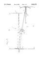
- FIG. 1 shows a side view of a preferable embodiment of the telescope according to the invention
- FIG. 2 shows a plane view of the preferable embodiment of FIG. 1.
- FIG. 1 shows a side view of a preferable embodiment of the telescope according to the invention.
- the telescope 1 comprises an entrance pupil 2, a first reflecting element 3 and a second reflecting element 4.
- the shape of the reflecting surface of the reflecting elements 3 and 4 is concave.
- a light beam 5 impinging on the telescope passes successively the entrance pupil 2, the first reflecting element 3 and the second reflecting element 4.
- the construction of the telescope 1 is such that the first reflecting element 3 images the entrance pupil 2 approximately in the focus of the second reflecting element 4. This has the advantage that all of the impinging light beams leave the telescope nearly parallel to each other.
- the outgoing light beams 5 impinge thus also nearly perpendicular on a spectrometer located in use after the telescope, of which only the entrance slot 6 is shown.
- the telescope according to the invention facilitates the use of the telescope according to the invention in combination with a spectrometer having small dimensions.
- a sufficient image of the object to be tested could be formed at the entrance slot of a relatively small spectrometer after all.
- the telescope 1 provides an image of the object on the spectrometer in a nearly straight image plane in contrast to the known telescope resulting in a curved image plane.
- the telescope according to the invention is suitable for using it in combination with practically all known imaging spectrometers.
- FIG. 2 shows a plan view of the preferable embodiment of FIG. 1.
- the angle ⁇ is a measure for the field of vision of the telescope 1.
- the telescope 1 has an angle ⁇ 90 degrees.
- ⁇ 30 degrees is valid for the known telescope.
- the telescope according to the invention results thus in a substantial improvement in field of vision in comparison to the known telescope.
- the telescope according to the invention has, just like the known telescope, in addition the advantage of relatively smaller dimensions, which will be explained later.
- the reflecting elements 3 and 4 are mirrors.
- the reflecting surface of the mirrors may be both spherical and aspherical in shape. Because of its simple manufacturing the use of mirrors with spherical surfaces is preferred. It will be clear for one skilled in the art that dependent on the aimed application many kinds of materials are suited for the reflecting surfaces. Examples of suitable materials are aluminum, optical glass types and materials with a partly amorphous and a partly crystalline structure such as Zerodur®. Preferable both of the mirrors have an angle of inclination ⁇ approximately lying between 0 and 25 degrees.
- the radius of curvature of the mirror 3 is nearly 60.3 mm.
- the radius of curvature of mirror 4 is nearly 195 mm.
- the reflecting surfaces of the mirrors 3 and 4 are preferably polished.
- Entrance pupil 2 may comprise all kinds of light absorbing materials.
- the entrance pupil has preferably an electrical opening of approximately 6.4 mm by 3.3 mm. In the shown embodiment the entrance pupil is positioned horizontally with the long axis seen in the plane of FIG. 2.
- the entrance pupil 2 is located at a distance l1 of approximately 37 mm as to mirror 3.
- Mirrors 3 and 4 are spaced at a mutual distance 12 of approximately 230 mm.
- Mirror 4 is arranged at a distance 13 of nearly 190.4 mm from the entrance slot 6 of the spectrometer.
- an accuracy of at least 1% and more preferably 0.2% is preferably valid for all of the distances and radii of curvature.
- the mentioned dimensions are only illustrative and are by no means meant to limit the invention.
- the dimensions illustrate indeed the handy size of the preferred embodiment of the telescope according to the invention. This handy size is substantially advantageous, in particular in locating the telescope in a satellite or aeroplane, such as in the above described application in an Ozone Monitoring Instrument.
- the mentioned dimensions indicate further only in proportions the mutual distances and sizes of the components in the shown configuration. If desired the whole configuration could be upscaled by a predetermined factor. Thereby the large field of vision is maintained.
- a depolarizer 7 could be inserted in the light path between mirrors 3 and 4.
- the telescope according to the invention is favorably made polarization independent.
- Depolarizer 7 is built up preferably in a known way from four wedges from quartz crystal.
- a diaphragm 8 may be arranged behind depolarizer 7 for optimizing the operation of the telescope further.
- diaphragm 8 is located nearly in the focus of the second mirror 4.
- the opening of the diaphragm 8 is preferably smaller than the image of the entrance pupil 2 at the location of the diaphragm.
- the quantity of scattering light is minimized by means of diaphragm 8.
- the diaphragm serves that the transmitted quantity of light for all of the angles of vision are nearly equal.
- Diaphragm 8 is preferably manufactured from light absorbing material.
- the telescope according to the invention may be implemented for example with lenses instead of mirrors.
- the use of lenses has the disadvantage that so called "color errors" will occur. This means among others that it is difficult feasible with lenses to image light of different wavelengths with an equal spot size.
Abstract
Telescope comprising two or more reflecting elements, wherein a light beam impinging on a first reflecting element leaves through a second reflecting element, in which the shape of the reflecting surface of the second reflecting element is concave. The shape of the reflecting surface of the first reflecting element is concave. An entrance pupil is arranged in the light path in front of the first reflecting element and the first reflecting element images the entrance pupil nearly in the focus of the second reflecting element.
Description
The invention relates to a telescope comprising two or more reflecting elements, in which a light beam impinging on a first reflecting element leaves through a second reflecting element, in which the shape of the reflecting surface of the second reflecting element is concave.
Such a telescope could be placed in practice for example in front of an imaging spectrometer for imaging an object at its entrance slot. The combination of imaging spectrometer and telescope could be provided for example in a satellite or an aeroplane and could be used for example for chartering or monitoring the ozone layer.
A telescope of the type mentioned at the beginning is known from DE-A-3614639. The known telescope consists of a first convex and a second concave mirror and has advantageous relatively small dimensions. However, the known telescope has the disadvantage that its field of vision is limited. In the above mentioned application this results for example in a satellite, which must revolve many times around the earth for covering a predetermined area of the ozone layer.
This invention has the object to provide a telescope of the type mentioned above having comparable dimensions but having a larger field of vision.
The telescope according to this invention is therefore characterized in that the shape of the reflecting surface of the first reflecting element is concave, that an entrance pupil is located in the light path in front of the first reflecting element and that the first reflecting element images the entrance pupil approximately in the focus of the second reflecting element.
Moreover, the telescope according to the invention has the advantage that the light beam impinging on the telescope leaves nearly parallel to each other. Therefore, the outgoing light beams will impinge nearly perpendicular to the entrance slot of a spectrometer located in use behind the telescope. Consequently, the telescope according to the invention is suitable for using it in nearly all of the known spectrometers. Because of said nearly perpendicular incidence of the light beams the telescope according to the invention may also be used in combination with a spectrometer having small dimensions. Thereby no additional elements are required for diminishing the angle of incidence of such a spectrometer. The possibility of using a small spectrometer is particularly advantageous in the above mentioned implementation because of the small available space in a satellite or aeroplane.
This invention will be described in more details by reference to the accompanying drawings, in which
FIG. 1 shows a side view of a preferable embodiment of the telescope according to the invention;
FIG. 2 shows a plane view of the preferable embodiment of FIG. 1.
In both of the figures similar elements are indicated by equal reference numbers.
FIG. 1 shows a side view of a preferable embodiment of the telescope according to the invention. In the shown embodiment the telescope 1 comprises an entrance pupil 2, a first reflecting element 3 and a second reflecting element 4. The shape of the reflecting surface of the reflecting elements 3 and 4 is concave. A light beam 5 impinging on the telescope passes successively the entrance pupil 2, the first reflecting element 3 and the second reflecting element 4. The construction of the telescope 1 is such that the first reflecting element 3 images the entrance pupil 2 approximately in the focus of the second reflecting element 4. This has the advantage that all of the impinging light beams leave the telescope nearly parallel to each other. The outgoing light beams 5 impinge thus also nearly perpendicular on a spectrometer located in use after the telescope, of which only the entrance slot 6 is shown. This facilitates the use of the telescope according to the invention in combination with a spectrometer having small dimensions. By said nearly perpendicular incidence of the light beams on such a spectrometer also a sufficient image of the object to be tested could be formed at the entrance slot of a relatively small spectrometer after all. Furthermore, the telescope 1 provides an image of the object on the spectrometer in a nearly straight image plane in contrast to the known telescope resulting in a curved image plane. In view of the above mentioned description it will be clear that the telescope according to the invention is suitable for using it in combination with practically all known imaging spectrometers.
FIG. 2 shows a plan view of the preferable embodiment of FIG. 1. The angle α is a measure for the field of vision of the telescope 1. In the shown embodiment the telescope 1 has an angle α≧90 degrees. In contrast α≦30 degrees is valid for the known telescope. The telescope according to the invention results thus in a substantial improvement in field of vision in comparison to the known telescope. With the shown preferable embodiment the telescope according to the invention has, just like the known telescope, in addition the advantage of relatively smaller dimensions, which will be explained later.
In the known preferable embodiment the reflecting elements 3 and 4 are mirrors. The reflecting surface of the mirrors may be both spherical and aspherical in shape. Because of its simple manufacturing the use of mirrors with spherical surfaces is preferred. It will be clear for one skilled in the art that dependent on the aimed application many kinds of materials are suited for the reflecting surfaces. Examples of suitable materials are aluminum, optical glass types and materials with a partly amorphous and a partly crystalline structure such as Zerodur®. Preferable both of the mirrors have an angle of inclination β approximately lying between 0 and 25 degrees. In the known preferred embodiment the radius of curvature of the mirror 3 is nearly 60.3 mm. The radius of curvature of mirror 4 is nearly 195 mm. In order to minimize light scattering the reflecting surfaces of the mirrors 3 and 4 are preferably polished.
Entrance pupil 2 may comprise all kinds of light absorbing materials. The entrance pupil has preferably an electrical opening of approximately 6.4 mm by 3.3 mm. In the shown embodiment the entrance pupil is positioned horizontally with the long axis seen in the plane of FIG. 2.
In the shown preferable embodiment the entrance pupil 2 is located at a distance l1 of approximately 37 mm as to mirror 3. Mirrors 3 and 4 are spaced at a mutual distance 12 of approximately 230 mm. Mirror 4 is arranged at a distance 13 of nearly 190.4 mm from the entrance slot 6 of the spectrometer. For a good operation of the telescope 1 an accuracy of at least 1% and more preferably 0.2% is preferably valid for all of the distances and radii of curvature.
It is self-evident that the mentioned dimensions are only illustrative and are by no means meant to limit the invention. The dimensions illustrate indeed the handy size of the preferred embodiment of the telescope according to the invention. This handy size is substantially advantageous, in particular in locating the telescope in a satellite or aeroplane, such as in the above described application in an Ozone Monitoring Instrument. The mentioned dimensions indicate further only in proportions the mutual distances and sizes of the components in the shown configuration. If desired the whole configuration could be upscaled by a predetermined factor. Thereby the large field of vision is maintained.
Optionally a depolarizer 7 could be inserted in the light path between mirrors 3 and 4. In this way the telescope according to the invention is favorably made polarization independent. This is also true for any instrument located thereafter, such as the spectrometer. Depolarizer 7 is built up preferably in a known way from four wedges from quartz crystal.
Moreover, a diaphragm 8 may be arranged behind depolarizer 7 for optimizing the operation of the telescope further. Preferably, diaphragm 8 is located nearly in the focus of the second mirror 4. The opening of the diaphragm 8 is preferably smaller than the image of the entrance pupil 2 at the location of the diaphragm. The quantity of scattering light is minimized by means of diaphragm 8. In addition the diaphragm serves that the transmitted quantity of light for all of the angles of vision are nearly equal. Diaphragm 8 is preferably manufactured from light absorbing material.
Without any doubt many embodiments and modifications of the described telescope will appear to those skilled in the art. The telescope according to the invention may be implemented for example with lenses instead of mirrors. The use of lenses, however, has the disadvantage that so called "color errors" will occur. This means among others that it is difficult feasible with lenses to image light of different wavelengths with an equal spot size.
The telescope according to the invention is naturally not limited to the described and illustrated embodiment, but comprises any embodiment being consistent with the above description and the enclosed drawings and being with the scope of the enclosed claims.
Claims (7)
1. A telescope comprising:
a first reflecting element and a second reflecting element, in which a light beam impinging on the first reflecting element is reflected to and then reflected from the second reflecting element, and in which the first and second reflecting elements have concave reflecting surfaces; and
an aperture stop, comprised of a first diaphragm positioned between the first and second reflecting elements substantially in a focus of the second reflecting element; wherein an angle of inclination and a radius of curvature of the first and second reflecting elements are such that the telescope has a field of vision wider than 30 degrees in one direction.
2. The telescope of claim 1, wherein an entrance pupil is located in front of said first reflecting element in a light path of the light beam impinging on the first reflecting element.
3. The telescope of claim 2, wherein the reflecting surface of the first reflecting element has a radius of curvature of about 60.3 mm, the reflecting surface of the second reflecting element has a radius of curvature of about 195 mm, the distance between the entrance pupil and the first reflecting element is about 37 mm and the distance between the first and the second reflecting elements is about 230 mm.
4. The telescope of claim 7, wherein the angle of inclination of the optical axes of the first and second reflecting elements is less than approximately 25 degrees.
5. The telescope of claim 1, further comprising a depolarizer located in the light path between the first and second reflecting elements.
6. A telescope comprising:
first and second reflecting elements having concave reflecting surfaces, in which a light beam impinging on the first reflecting element is reflected to and then reflected from the second reflecting element; and
an entrance pupil located in the light path in front of the first reflecting element so that the focus of the second reflecting surface is intermediate the entrance pupil and the second reflecting surface;
wherein the reflecting surface of the first reflecting element has a radius of curvature of about 60.3 mm, the reflecting surface of the second reflecting element has a radius of curvature of about 195 mm, the distance between the entrance pupil and the first reflecting element is approximately 37 mm, and the distance between the first and the second reflecting elements is approximately 230 mm.
7. The telescope of claim 6, wherein a depolarizer is located in a light path between the first and the second reflecting elements.
Applications Claiming Priority (2)
| Application Number | Priority Date | Filing Date | Title |
|---|---|---|---|
| NL1001952A NL1001952C2 (en) | 1995-12-21 | 1995-12-21 | Telescope with large field of view. |
| NL1001952 | 1995-12-21 |
Publications (1)
| Publication Number | Publication Date |
|---|---|
| US5841575A true US5841575A (en) | 1998-11-24 |
Family
ID=19762064
Family Applications (1)
| Application Number | Title | Priority Date | Filing Date |
|---|---|---|---|
| US08/773,517 Expired - Lifetime US5841575A (en) | 1995-12-21 | 1996-12-23 | Telescope with a large field of vision |
Country Status (3)
| Country | Link |
|---|---|
| US (1) | US5841575A (en) |
| EP (1) | EP0780669A1 (en) |
| NL (1) | NL1001952C2 (en) |
Cited By (5)
| Publication number | Priority date | Publication date | Assignee | Title |
|---|---|---|---|---|
| CN100342260C (en) * | 2002-10-08 | 2007-10-10 | 原子能委员会 | Amplified, achromatic and absorption reducing light collecting system, particularly adapted to optical spectrometric analysis |
| EP2418529A1 (en) | 2010-08-12 | 2012-02-15 | Nederlandse Organisatie voor toegepast -natuurwetenschappelijk onderzoek TNO | Anamorphotic telescope |
| CN102565003A (en) * | 2011-12-22 | 2012-07-11 | 中国科学院安徽光学精密机械研究所 | Driven multi-shaft difference absorption spectrometer system using pinhole slit |
| CN103197410A (en) * | 2013-03-04 | 2013-07-10 | 中国科学院长春光学精密机械与物理研究所 | Oversized view field off-axis reflection system used for imaging spectrometer |
| US20160274348A1 (en) * | 2015-03-17 | 2016-09-22 | Hiroshi Taniguchi | Telescope, and method for manufacturing telescope |
Families Citing this family (1)
| Publication number | Priority date | Publication date | Assignee | Title |
|---|---|---|---|---|
| FR2797949B1 (en) * | 1999-08-26 | 2001-10-19 | Cit Alcatel | HIGH RESOLUTION INFRARED SPECTROMETRY INSTRUMENT |
Citations (17)
| Publication number | Priority date | Publication date | Assignee | Title |
|---|---|---|---|---|
| GB329088A (en) * | 1929-03-22 | 1930-05-15 | John Ernest Tilly | An extensible roof attachment for motor cars, caravans and the like |
| US2697379A (en) * | 1953-09-16 | 1954-12-21 | Joseph B Walker | Compound image-forming reflecting mirror optical system |
| US2869423A (en) * | 1954-05-03 | 1959-01-20 | Legare W Hoge | Reflective optical systems |
| US2970518A (en) * | 1958-12-29 | 1961-02-07 | Karl F Ross | Catoptric system |
| US3353893A (en) * | 1967-04-06 | 1967-11-21 | Steven H Bamberger | Rear view automotive periscope utilizing toric mirrors |
| US3811749A (en) * | 1972-10-12 | 1974-05-21 | Honeywell Inc | Wide field reflective optical apparatus |
| US4265510A (en) * | 1979-05-16 | 1981-05-05 | Hughes Aircraft Company | Three mirror anastigmatic optical system |
| US4443058A (en) * | 1981-09-22 | 1984-04-17 | The United States Of America As Represented By The Secretary Of The Army | Test image projector for testing imaging devices |
| EP0129289A2 (en) * | 1983-06-15 | 1984-12-27 | Philips Electronics Uk Limited | A slit imaging system using two concave mirrors |
| US4598981A (en) * | 1985-02-05 | 1986-07-08 | The United States Of America As Represented By The Administrator Of The National Aeronautics And Space Administration | Wide-angle flat field telescope |
| US4733955A (en) * | 1986-04-14 | 1988-03-29 | Hughes Aircraft Company | Reflective optical triplet having a real entrance pupil |
| US4773756A (en) * | 1986-04-30 | 1988-09-27 | Messerschmitt-Boelkow-Blohm Gmbh | Imaging spectrometer having a wide spectral range |
| US4927256A (en) * | 1988-07-26 | 1990-05-22 | Societe D'applications Generales D'electricite Et De Mecanique Sagem | Multispectral optical device comprising mirrors |
| US5153772A (en) * | 1991-04-09 | 1992-10-06 | Toledyne Industries, Inc. | Binary optic-corrected multistage imaging system |
| US5231462A (en) * | 1991-03-04 | 1993-07-27 | Landis & Gyr Betriebs Ag | Optical spectrophotometer with wavelength modulation |
| US5287218A (en) * | 1992-04-07 | 1994-02-15 | Hughes Aircraft Company | Re-imaging optical system including refractive and diffractive optical elements |
| US5477395A (en) * | 1994-11-14 | 1995-12-19 | Hughes Aircraft Company | Two nested all-reflective afocal telescopes providing four fields of view |
-
1995
- 1995-12-21 NL NL1001952A patent/NL1001952C2/en not_active IP Right Cessation
-
1996
- 1996-12-19 EP EP96203631A patent/EP0780669A1/en not_active Ceased
- 1996-12-23 US US08/773,517 patent/US5841575A/en not_active Expired - Lifetime
Patent Citations (17)
| Publication number | Priority date | Publication date | Assignee | Title |
|---|---|---|---|---|
| GB329088A (en) * | 1929-03-22 | 1930-05-15 | John Ernest Tilly | An extensible roof attachment for motor cars, caravans and the like |
| US2697379A (en) * | 1953-09-16 | 1954-12-21 | Joseph B Walker | Compound image-forming reflecting mirror optical system |
| US2869423A (en) * | 1954-05-03 | 1959-01-20 | Legare W Hoge | Reflective optical systems |
| US2970518A (en) * | 1958-12-29 | 1961-02-07 | Karl F Ross | Catoptric system |
| US3353893A (en) * | 1967-04-06 | 1967-11-21 | Steven H Bamberger | Rear view automotive periscope utilizing toric mirrors |
| US3811749A (en) * | 1972-10-12 | 1974-05-21 | Honeywell Inc | Wide field reflective optical apparatus |
| US4265510A (en) * | 1979-05-16 | 1981-05-05 | Hughes Aircraft Company | Three mirror anastigmatic optical system |
| US4443058A (en) * | 1981-09-22 | 1984-04-17 | The United States Of America As Represented By The Secretary Of The Army | Test image projector for testing imaging devices |
| EP0129289A2 (en) * | 1983-06-15 | 1984-12-27 | Philips Electronics Uk Limited | A slit imaging system using two concave mirrors |
| US4598981A (en) * | 1985-02-05 | 1986-07-08 | The United States Of America As Represented By The Administrator Of The National Aeronautics And Space Administration | Wide-angle flat field telescope |
| US4733955A (en) * | 1986-04-14 | 1988-03-29 | Hughes Aircraft Company | Reflective optical triplet having a real entrance pupil |
| US4773756A (en) * | 1986-04-30 | 1988-09-27 | Messerschmitt-Boelkow-Blohm Gmbh | Imaging spectrometer having a wide spectral range |
| US4927256A (en) * | 1988-07-26 | 1990-05-22 | Societe D'applications Generales D'electricite Et De Mecanique Sagem | Multispectral optical device comprising mirrors |
| US5231462A (en) * | 1991-03-04 | 1993-07-27 | Landis & Gyr Betriebs Ag | Optical spectrophotometer with wavelength modulation |
| US5153772A (en) * | 1991-04-09 | 1992-10-06 | Toledyne Industries, Inc. | Binary optic-corrected multistage imaging system |
| US5287218A (en) * | 1992-04-07 | 1994-02-15 | Hughes Aircraft Company | Re-imaging optical system including refractive and diffractive optical elements |
| US5477395A (en) * | 1994-11-14 | 1995-12-19 | Hughes Aircraft Company | Two nested all-reflective afocal telescopes providing four fields of view |
Cited By (8)
| Publication number | Priority date | Publication date | Assignee | Title |
|---|---|---|---|---|
| CN100342260C (en) * | 2002-10-08 | 2007-10-10 | 原子能委员会 | Amplified, achromatic and absorption reducing light collecting system, particularly adapted to optical spectrometric analysis |
| EP2418529A1 (en) | 2010-08-12 | 2012-02-15 | Nederlandse Organisatie voor toegepast -natuurwetenschappelijk onderzoek TNO | Anamorphotic telescope |
| WO2012021063A1 (en) | 2010-08-12 | 2012-02-16 | Nederlandse Organisatie Voor Toegepast-Natuurwetenschappelijk Onderzoek Tno | Anamorphotic telescope |
| US9304300B2 (en) | 2010-08-12 | 2016-04-05 | Nederlandse Organisatie Voor Toegepast-Natuurwetenschappelijk Onderzoek Tno | Anamorphotic telescope |
| CN102565003A (en) * | 2011-12-22 | 2012-07-11 | 中国科学院安徽光学精密机械研究所 | Driven multi-shaft difference absorption spectrometer system using pinhole slit |
| CN103197410A (en) * | 2013-03-04 | 2013-07-10 | 中国科学院长春光学精密机械与物理研究所 | Oversized view field off-axis reflection system used for imaging spectrometer |
| US20160274348A1 (en) * | 2015-03-17 | 2016-09-22 | Hiroshi Taniguchi | Telescope, and method for manufacturing telescope |
| US10268034B2 (en) * | 2015-03-17 | 2019-04-23 | Hiroshi Taniguchi | Telescope, and method for manufacturing telescope |
Also Published As
| Publication number | Publication date |
|---|---|
| NL1001952C2 (en) | 1997-06-24 |
| EP0780669A1 (en) | 1997-06-25 |
Similar Documents
| Publication | Publication Date | Title |
|---|---|---|
| JP2763055B2 (en) | Reflective optical triplet with real entrance pupil | |
| Eisenhauer et al. | SINFONI: integral field spectroscopy at 50-milli-arcsecond resolution with the ESO VLT | |
| US5127728A (en) | Compact prism spectrograph suitable for broadband spectral surveys with array detectors | |
| US4964706A (en) | Multi-focal length, multi-field of view three mirror anastrigmat | |
| US4624528A (en) | Scanning systems with polygon scanner having curved facets | |
| JP2908795B2 (en) | Compact optical wavelength identification radiometer | |
| US3811749A (en) | Wide field reflective optical apparatus | |
| US8011793B2 (en) | Wide field four mirror telescope using off-axis aspherical mirrors | |
| US5768040A (en) | Wide field-of-view imaging spectrometer | |
| JPH06273671A (en) | High-speed reflecting system, which has wide angle and returns large, clear image | |
| US3963328A (en) | Wide field reflective optical apparatus | |
| EP0766112B1 (en) | Panoramic optics assembly having an initial flat reflective element | |
| JPH04253B2 (en) | ||
| US7616378B2 (en) | Dichroic beam splitter and related apparatus and methods | |
| EP0433613B1 (en) | Microscopic spectrometer with Cassegrain objective | |
| US5841575A (en) | Telescope with a large field of vision | |
| US6789908B2 (en) | Confocal ellipsoidal mirror system for wide field of view imaging | |
| US4202597A (en) | Optical scanning system with compensation for unwanted image rotation during scanning | |
| Schmidt et al. | Optical design concept for the Giant Magellan Telescope Multi-object Astronomical and Cosmological Spectrograph (GMACS) | |
| EP0353138B1 (en) | Multispectral mirror device | |
| JP5128037B2 (en) | Stereo image acquisition device | |
| JP2003005073A (en) | Off-axis reflection optical system | |
| US6356388B1 (en) | Wide-angle catoptric focal system with mirrors | |
| US6674571B2 (en) | Optical architecture for an observation telescope, in particular a telescope for observing the earth from a satellite | |
| JP3045483B2 (en) | Reflective optical system |
Legal Events
| Date | Code | Title | Description |
|---|---|---|---|
| AS | Assignment |
Owner name: NEDERLANDSE ORGANISATIE VOOR TOEGEPAST-NATUURWETEN Free format text: ASSIGNMENT OF ASSIGNORS INTEREST;ASSIGNORS:VISSER, HUIB;SNIJDERS, BART;REEL/FRAME:008453/0503 Effective date: 19970130 |
|
| STCF | Information on status: patent grant |
Free format text: PATENTED CASE |
|
| FEPP | Fee payment procedure |
Free format text: PAYOR NUMBER ASSIGNED (ORIGINAL EVENT CODE: ASPN); ENTITY STATUS OF PATENT OWNER: LARGE ENTITY |
|
| FPAY | Fee payment |
Year of fee payment: 4 |
|
| FPAY | Fee payment |
Year of fee payment: 8 |
|
| FPAY | Fee payment |
Year of fee payment: 12 |