US7651006B2 - Stamped bucket for vending machine and method of forming same - Google Patents
Stamped bucket for vending machine and method of forming same Download PDFInfo
- Publication number
- US7651006B2 US7651006B2 US10/430,992 US43099203A US7651006B2 US 7651006 B2 US7651006 B2 US 7651006B2 US 43099203 A US43099203 A US 43099203A US 7651006 B2 US7651006 B2 US 7651006B2
- Authority
- US
- United States
- Prior art keywords
- wall
- end wall
- elongated
- bucket
- extending
- Prior art date
- Legal status (The legal status is an assumption and is not a legal conclusion. Google has not performed a legal analysis and makes no representation as to the accuracy of the status listed.)
- Expired - Fee Related, expires
Links
Images


Classifications
-
- G—PHYSICS
- G07—CHECKING-DEVICES
- G07F—COIN-FREED OR LIKE APPARATUS
- G07F13/00—Coin-freed apparatus for controlling dispensing or fluids, semiliquids or granular material from reservoirs
- G07F13/10—Coin-freed apparatus for controlling dispensing or fluids, semiliquids or granular material from reservoirs with associated dispensing of containers, e.g. cups or other articles
-
- G—PHYSICS
- G07—CHECKING-DEVICES
- G07F—COIN-FREED OR LIKE APPARATUS
- G07F11/00—Coin-freed apparatus for dispensing, or the like, discrete articles
- G07F11/02—Coin-freed apparatus for dispensing, or the like, discrete articles from non-movable magazines
- G07F11/04—Coin-freed apparatus for dispensing, or the like, discrete articles from non-movable magazines in which magazines the articles are stored one vertically above the other
- G07F11/16—Delivery means
-
- Y—GENERAL TAGGING OF NEW TECHNOLOGICAL DEVELOPMENTS; GENERAL TAGGING OF CROSS-SECTIONAL TECHNOLOGIES SPANNING OVER SEVERAL SECTIONS OF THE IPC; TECHNICAL SUBJECTS COVERED BY FORMER USPC CROSS-REFERENCE ART COLLECTIONS [XRACs] AND DIGESTS
- Y10—TECHNICAL SUBJECTS COVERED BY FORMER USPC
- Y10T—TECHNICAL SUBJECTS COVERED BY FORMER US CLASSIFICATION
- Y10T29/00—Metal working
- Y10T29/49—Method of mechanical manufacture
- Y10T29/49826—Assembling or joining
- Y10T29/49947—Assembling or joining by applying separate fastener
Definitions
- This invention relates to the art of vending machines and, more particularly, to a bucket for use in a vending machine that is formed or stamped from a sheet of metal.
- Vending machines including those adapted to dispense beverage containers, such as cans and plastic bottles, for example, are well known and widely used. Vending machines commonly use a component known as a basket, rotor or bucket to selectively dispense the beverage containers and/or other products from the vending machine.
- a component known as a basket, rotor or bucket to selectively dispense the beverage containers and/or other products from the vending machine.
- the buckets work in conjunction with various other components of the vending machine to ensure that only one beverage container or other product is dispensed per vend operation. As such, these components are known to take various forms and configurations depending upon the structure and features of the other surrounding components. However, it is generally desirable for these components to be of a thin-walled construction so that the overall size thereof can be minimized. This avoids interference with other associated parts and components, and also generally contributes to minimizing or reducing the overall size of the vending machine.
- a bucket typically includes an elongated body portion that is at least somewhat cylindrically shaped.
- the body portion includes an inside surface that forms a channel that extends longitudinally along the body portion between a pair of opposing end walls.
- the bucket is typically supported within the vending machine on each of the end walls.
- a bearing surface is often provided on each end wall for engaging the vending machine.
- suitable features can be provided on one of the end walls for transmitting rotational motion from a motor or other actuator located within the vending machine.
- buckets are typically disposed horizontally within a vending machine and must be sufficiently rigid to support the force of two or more beverage containers falling vertically from above into the bucket. Additionally, a torsional load is also applied to the bucket as the same rotates to dispense the individual beverage containers. As such, the bucket must have sufficient torsional rigidity to withstand any such load. Due to the desired thin-walled construction discussed above, buckets molded from polymeric materials have been found to have insufficient rigidity. For this and other reasons, buckets are typically manufactured out of metallic materials, such as zinc or aluminum. Buckets manufactured from zinc are typically die cast, while buckets made of aluminum are commonly extruded with end walls attached thereto, such as by welding, for example.
- Die cast zinc buckets suffer from a number of disadvantages that tend to increase costs of the part and can also result in reduced quality.
- One such disadvantage is the extensive lead time that is commonly required for die casting such parts. It is well understood that longer lead times limit the manufacturers ability to react to market or customer demands.
- die casting tooling tends to wear significantly under production use, especially in areas of the tooling that produce tightly toleranced parts. As such, significant repair costs are often associated with maintaining die cast tooling in condition to produce such tightly toleranced parts.
- die cast parts commonly require secondary operations to produce a finished part. For example, certain features of die cast buckets are typically re-struck to finished dimensions and/or conditions after the die casting process. This further adds to the cost, as well as the already substantial lead time for die cast buckets.
- Aluminum buckets are typically manufactured by extruding the elongated body portion out of a suitable aluminum material. A pair of opposing end walls are then attached to the ends of the elongated body portion. Usually, the end walls are also formed from aluminum, and are manufactured in any suitable manner, such as being machined from bar stock, for example. The end walls can be attached to the elongated body portion in any suitable manner, however, welding is typically used.
- Aluminum buckets tend to suffer from the disadvantages similar to those discussed above. Namely, aluminum buckets are typically expensive to manufacture. This is due, at least in part, to material costs as well as the costs associated with secondary operations, such as machining and welding operations. As such, it is desirable to develop a bucket having the desired strength and rigidity but, also, that is efficient and economical to manufacture.
- a stamped bucket for a vending machine is provided that avoids or minimizes the problems and disadvantages encountered in connection with buckets of the foregoing character while promoting a desired simplicity of structure and economy of manufacture.
- a stamped bucket that includes an elongated body having opposing first and second ends.
- a first end wall is integrally formed on the body along the first end and extends in generally transverse relation to the same.
- the first end wall has a first tab portion extending therefrom that is secured to the body adjacent the first end.
- a second end wall is also integrally formed on the body along the second end thereof.
- the second end wall also extends in a generally transverse relation to the body, and an axis of rotation extends between the first and second end walls in substantial alignment with the body.
- the second end wall has a second tab portion that extends therefrom and is secured to the body adjacent the second end.
- a method of forming a bucket from a sheet of metal includes the step of forming a blank on the sheet of metal.
- the blank includes an elongated body portion having first and second opposing ends, a first end wall portion integrally formed on the first end of the body, and a second end wall portion integrally formed on the second end of the body. Additionally, a first elongated tab extends from one of the first body portion and the first end wall portion, and a second elongated tab extends from one of the body portion and the second end wall portion.
- Another step includes forming the first and second end wall portions generally transverse the elongated body portion.
- Still other steps include forming the first tab adjacent the other of the body portion and the first end wall portion, and forming the second tab adjacent the other of the body portion and the second end wall portion. Further steps include attaching the first tab to the other of the body portion and the first end wall portion, and attaching the second tab to the other of the body portion and the second end wall portion.
- stamped bucket is provided that is manufactured in accordance with the foregoing method.
- FIG. 1 is a perspective view of a stamped bucket in accordance with the present invention.
- FIG. 2 is another perspective view of the stamped bucket shown in FIG. 1 .
- FIG. 3 is a top plan view of a sheet of metal illustrating one step in forming the stamped bucket shown in FIG. 1 .
- FIG. 4 is a top plan view of the sheet of metal shown in FIG. 3 illustrating another step in forming the stamped bucket shown in FIG. 1 .
- FIG. 5 is a top plan view of the sheet of metal shown in FIG. 4 illustrating another step in forming the stamped bucket shown in FIG. 1 .
- FIG. 6 is a top plan view of a portion of the sheet of metal shown in FIG. 5 illustrating another step in forming the stamped bucket shown in FIG. 1 .
- FIG. 6A is a side elevation view, shown in cross section, of the portion of the sheet of metal shown in FIG. 6 taken along line 6 A- 6 A.
- FIG. 6B is a side elevation view, shown in cross section, of the portion of the sheet of metal shown in FIG. 6 taken along line 6 B- 6 B.
- FIG. 7 is a top plan view of the portion of the sheet of metal shown in FIG. 6 illustrating another step in forming the stamped bucket shown in FIG. 1 .
- FIG. 7A is a side elevation view, shown in cross section, of the portion of the sheet of metal shown in FIG. 7 taken along line 7 A- 7 A.
- FIG. 7B is a side elevation view, shown in cross section, of the portion of the sheet of metal shown in FIG. 7 taken along line 7 B- 7 B.
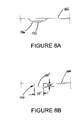
- FIG. 8 is a top plan view of the portion of the sheet of metal shown in FIG. 7 illustrating another step in forming the stamped bucket shown in FIG. 1 .
- FIG. 8A is a side elevation view, shown in cross section, of the portion of the sheet of metal shown in FIG. 8 taken along line 8 A- 8 A.
- FIG. 8B is a side elevation view, shown in cross section, of the portion of the sheet of metal shown in FIG. 8 taken along line 8 B- 8 B.
- FIG. 9 is a top plan view of the portion of the sheet of metal shown in FIG. 8 illustrating another step in forming the stamped bucket shown in FIG. 1 .
- FIG. 9A is a side elevation view, shown in cross section, of the portion of the sheet of metal shown in FIG. 9 taken along line 9 A- 9 A.
- FIG. 9B is a side elevation view, shown in cross section, of the portion of the sheet of metal shown in FIG. 9 taken along line 9 B- 9 B.
- FIG. 10 is a top plan view of the portion of the sheet of metal shown in FIG. 9 illustrating another step in forming the stamped bucket shown in FIG. 1 .
- FIG. 10A is a side elevation view, shown in cross section, of the portion of the sheet of metal shown in FIG. 10 taken along line 10 A- 10 A.
- FIG. 10B is a side elevation view, shown in cross section, of the portion of the sheet of metal shown in FIG. 10 taken along line 10 B- 10 B.
- FIG. 11 is a top plan view of the portion of the sheet of metal shown in FIG. 10 illustrating another step in forming the stamped bucket in FIG. 1 .
- FIG. 12 is a top plan view of the portion of the sheet of metal shown in FIG. 11 illustrating another step in forming the stamped bucket shown in FIG. 1 .
- FIG. 13 is a top plan view of the portion of the sheet of metal shown in FIG. 12 illustrating another step in forming the stamped bucket shown in FIG. 1 .
- FIG. 14 is a top plan view of the portion of the sheet of metal shown in FIG. 13 illustrating another step in forming the stamped bucket shown in FIG. 1 .
- FIG. 14A is a side elevation view, shown in cross section, of the portion of the sheet of metal shown in FIG. 14 taken along line 14 A- 14 A.
- FIG. 15 is a top plan view of the portion of the sheet of metal shown in FIG. 14 illustrating another step in forming the stamped bucket shown in FIG. 1 .
- FIG. 15A is a side elevation view, shown in cross section, of the portion of the sheet of metal shown in FIG. 15 taken along line 15 A- 15 A.
- FIG. 15B is a side elevation view, shown in cross section, of the portion of the sheet of metal shown in FIG. 15 taken along line 15 B- 15 B.
- FIG. 16 is a top plan view of the portion of the sheet of metal shown in FIG. 15 illustrating another step in forming the stamped bucket shown in FIG. 1 .
- FIG. 17 is a top plan view of the portion of the sheet of metal shown in FIG. 16 illustrating another step in forming the stamped bucket shown in FIG. 1 .
- FIG. 17A is a side elevation view, shown in cross section, of the portion of the sheet of metal shown in FIG. 17 taken along line 17 A- 17 A.
- FIG. 17B is a side elevation view, shown in cross section, of the portion of the sheet of metal shown in FIG. 17 taken along line 17 B- 17 B.
- FIG. 18 is a top plan view of the portion of the sheet of metal shown in FIG. 17 illustrating another step in forming the stamped bucket shown in FIG. 1 .
- FIG. 19 is a top plan view of the portion of the sheet of metal shown in FIG. 18 illustrating another step in forming the stamped bucket shown in FIG. 1 .
- FIG. 20 is a top plan view of the portion of the sheet of metal shown in FIG. 19 illustrating another step in forming the stamped bucket shown in FIG. 1 .
- FIG. 20A is a side elevation view, shown in cross section, of the portion of the sheet of metal shown in FIG. 20 taken along line 20 A- 20 A.
- FIG. 20B is a side elevation view, shown in cross section, of the portion of the sheet of metal shown in FIG. 20 taken along line 20 B- 20 B.
- FIG. 21 is a top plan view of the portion of the sheet of metal shown in FIG. 20 illustrating another step in forming the stamped bucket shown in FIG. 1 .
- FIG. 21A is a side elevation view, shown in cross section, of the portion of the sheet of metal shown in FIG. 21 taken along line 21 A- 21 A.
- FIG. 21B is a side elevation view, shown in cross section, of the portion of the sheet of metal shown in FIG. 21 taken along line 21 B- 21 B.
- FIGS. 1 and 2 illustrate a bucket 100 having an elongated body 102 and opposing end walls 104 and 106 .
- Elongated body 102 is shown in FIGS. 1 and 2 as having a generally planar bottom wall portion 108 and side wall portions 110 and 112 extending generally opposite one another from bottom wall portion 108 .
- Holes 109 are provided on bottom wall portion 108 . Such holes can be used for drainage of fluids collecting on bottom wall portion 108 , for example.
- Side wall portion 110 is faceted and includes a lower curvilinear section 114 extending from bottom wall portion 108 and an upper planar section 116 .
- side wall portion 112 is shown as being substantially curvilinear.
- buckets commonly take various forms, shapes, sizes, lengths and configurations.
- any suitable shape or form of wall portions 108 , 110 and 112 can be used without departing from the scope and intent of the present invention.
- a plurality of notches or steps 118 have been included on side wall portion 112 . However, it will be appreciated that the inclusion of such steps is optional.
- End walls 104 and 106 extend in generally transverse relation to elongated body 102 .
- Each of the end walls are integrally formed from the material forming elongated body 102 and are respectively connected thereto at corners 120 and 122 .
- the corners are shown as being approximately the same width as bottom wall portion 108 and integrally connect the end walls to the same. It will be appreciated, however, that any suitable size, shape or configuration of these corners can be used.
- End wall 104 includes an elongated tab 124 extending therefrom. The tab is folded or bent out of the plane of end wall 104 forming a corner 126 .
- tab 124 is substantially aligned with elongated body 102 such that the tab is in abutting engagement with side wall portion 110 of the body.
- an elongated tab 128 extends from end wall 106 forming a corner 130 therebetween.
- tab 128 extends in substantial alignment with body 102 and is in abutting engagement with side wall portion 110 .
- Another elongated tab 132 extends from end wall 106 forming a corner 134 .
- Tab 132 preferably extends in substantial alignment with body 102 and is in abutting engagement with side wall portion 112 . It will be appreciated that in other embodiments, one or more of the tabs can extend from the side wall portion, or other portions of the elongated body, and abuttingly engage the end walls. Such embodiments are distinctly intended to be included within the scope and intent of the present invention.
- Each of tabs 124 , 128 and 132 are secured to elongated body 102 using a suitable manner of joining or attachment, including fastening, such as by rivets, screws or bolts, for example, and/or joining, such as by welding, for example.
- the tabs are attached to respective side wall portions of the elongated body by using an upset-pressing style fastener.
- One such fastener that is suitable for the present application is sold under the designation or trademark TOX by Tox Pressotechnik GmbH & Co. KG of Weingarten, Germany.
- two TOX joints 136 are used on each of tabs 124 , 128 and 132 to attach the same to elongated body 102 .
- upper planar section 116 of side wall portion 110 includes two offset areas 138 and 140 respectively adjacent tabs 124 and 128 .
- the offset areas extend inwardly from the upper planar section a sufficient distance to accommodate the associated tabs.
- the outside surface of each tab can be substantially aligned with the outside surface of side wall portion 110 .
- side wall portion 112 does not include an offset area adjacent tab 132 , as can be seen in FIG. 2 .
- a boss 148 projects outwardly from end wall 104 .
- the boss is shown in FIGS. 1 and 2 as being substantially circular. However, it will be appreciated that any suitable shape or configuration can be used.
- end wall 104 includes an opening 142 extending therethrough that includes a plurality of inside walls 144 and a radially outwardly extending locating feature 146 .
- the bucket is rotated during vend operations, and the vending machine includes a motor or other actuator operatively associated with the bucket and engaging opening 142 to transmit rotational motion to the bucket.
- opening 142 is shown as being non-circular to transmit such motion. It will be appreciate, however, that any feature or arrangement of features suitable for transmitting such rotary motion can be used.
- End wall 106 includes a boss 150 projecting therefrom.
- Boss 150 is shown in FIGS. 1 and 2 as being substantially cylindrical and has an opening 152 extending therethrough.
- Bosses 148 and 150 are substantially coaxially aligned with one another define an axis 154 extending along bucket 100 about which the same rotates when in use on a vending machine. It will be appreciated that the elongated body in conjunction with the end walls form a channel or cavity (not numbered) suitable for supporting and retaining vended products, such as beverage containers, for example.
- FIGS. 3-21 illustrate various steps, operations or other processes that can be utilized to form a stamped bucket in accordance with the present invention.
- Various areas, details and/or features of the bucket are formed, in whole or in part, in one or more of the steps.
- the discussion of FIGS. 3-21 hereinafter will typically make reference to those features or characteristics being created or modified by the step or process under discussion.
- various intermediate forms of the finished features may be produced in certain steps of the forming process, and that such intermediate forming steps are intended to be optionally included.
- FIG. 3 shows a strip or sheet of material 156 having a leading edge 158 that will be progressively moved through a die set or other suitable arrangement (not shown) for forming a stamped bucket in accordance with the present invention.
- steps or operations such as those shown in FIGS. 3-5 , can be used to form a bucket blank 160 ( FIG. 5 ) from the sheet of material.
- the bucket blanks move progressively through the die arrangement (not shown) to form a stamped bucket in accordance with the present invention.
- a plurality of passages such as holes 109 are formed on sheet 156 .
- areas 162 , 164 and 166 are removed from the sheet of material.
- these areas are formed by a stamping-type operation.
- other methods of removing these areas can be used, such as laser cutting, for example.
- areas 168 , 170 and 172 are similarly removed from the sheet of material. It will be appreciated that original areas 160 , 162 and 164 provide various aspects and portions of the features that form blank 160 , and that such features can include intermediate forms as mentioned above. As can be seen in FIG.
- holes 109 and areas 162 , 164 and 166 are formed at the stage removing areas 168 , 170 and 172 , holes 109 ′ and areas 162 ′, 164 ′ and 166 ′ are preferably simultaneously formed at the first stage shown in FIG. 3 . It will be further appreciated from FIG. 4 that partial blank 174 that includes leading edge 158 will be unsuitable for the formation of a bucket in accordance with the present invention.
- bucket blank 160 includes holes 109 and is formed in part by area 164 , areas 162 ′ and 166 ′, as well as areas 168 ′ 170 ′ and 172 ′ that are being formed in this stage. Additionally, it will be appreciated that holes 109 ′′ have been formed at the first stage, along with areas 162 ′′, 164 ′′ and 168 ′′. It will be appreciated that the drawings and discussion thereof will primarily refer to blank 160 .
- FIG. 6 illustrates a bucket blank 160 having a plurality of holes 109 provided on an elongated body portion 176 that has opposing ends 178 and 180 .
- integralally formed on blank 160 are end wall portions 182 and 184 .
- elongated body portion 176 is ultimately formed into body 102 of bucket 100 and, likewise, end wall portions 182 and 184 are respectively formed into end walls 104 and 106 .
- steps 118 of side wall portion 112 are provided on blank 176 due to the operations shown in and described with regard to FIGS. 4 and 5 .
- areas 186 and 188 respectively on end wall portions 182 and 184 are formed at this stage.
- Area 186 is shown in FIG. 6A as having a diameter dimension D 1 and a depth dimension D 2 .
- area 188 has a diameter dimension D 3 and a depth dimension D 4 .
- end wall portions 182 and 184 of bucket blank 160 are further formed in this step or stage to respectively include areas 186 ′ and 188 ′.
- area 186 ′ has a diameter dimension of D 1 ′ and a depth dimension of D 2 ′.
- dimensions D 1 ′ and D 2 ′ are less than dimensions D 1 and D 2 shown in and described with regard to FIG. 6A .
- area 188 ′ has a diameter dimension of D 3 ′ and depth dimension of D 4 ′.
- dimensions D 3 ′ and D 4 ′ are preferably less than dimensions D 3 and D 4 shown in and described with regard to FIG. 6B . It will be appreciated that the forming of area 186 ′ at this stage substantially completes the formation of boss 148 .
- FIG. 8 shows area 186 ′ of end wall portion 182 being further formed in this step or stage to include area 190 , which is coined or deformed from area 186 ′, as shown in FIG. 8A .
- end wall portion 184 is further formed to include area 188 ′′ having a diameter dimension of D 3 ′′ and a depth dimension of D 4 ′′, as shown in FIG. 8B , substantially completing the formation of boss 150 .
- dimension D 3 ′′ is less than dimension D 3 ′ shown in and described with regard to FIG. 7B .
- dimension D 4 ′′ is preferably greater than dimension D 4 ′ shown in and described with regard to FIG. 7B .
- opening 142 is formed on end wall portion 182 of bucket blank 160 .
- a downwardly displaced or coined area 192 is formed adjacent boss 150 .
- opening 142 includes a plurality of inside walls 144 and a locating feature 146 ( FIG. 9 ). It will be appreciated that inside walls 144 have a dimension D 5 that is preferably less than dimension D 2 ′ shown in FIG. 7A .
- FIG. 10 illustrates a further step or stage in which area 192 is trimmed or otherwise removed from end wall portion 182 . Additionally, areas 194 and 196 are trimmed or otherwise removed from end wall portion 184 . Opening 152 is formed through boss 150 by piercing or otherwise removing area 198 , as shown in FIG. 10B . Furthermore, areas 200 and 202 respectively on ends 178 and 180 of body portion 176 are displaced upwardly from the body portion, as shown in FIG. 10A , to respectively form offset areas 138 and 140 shown in FIG. 2 . It will be appreciated that areas 200 and 202 are optional, as mentioned above, and can alternately be displaced downwardly or take any other suitable form or configuration.
- end wall portion 182 of bucket blank 160 is further modified in this step or stage by trimming or otherwise removing areas 204 and 206 therefrom.
- areas 208 and 210 are likewise trimmed or otherwise removed.
- the formation of tab 132 is substantially completed by the removal of area 208 .
- peripheral edges 212 and 214 are substantially formed, as shown in FIG. 12 .
- areas 216 and 218 are respectively trimmed or otherwise removed from end wall portions 182 and 184 substantially forming tabs 124 and 128 , respectively. Additional steps, such as coining or otherwise breaking edges of the bucket blank, can optionally be performed at this or other stages, as desired.
- FIGS. 13-14 various steps and/or operations are illustrated. It will be appreciated that one or more of these steps can be performed simultaneously during a single stage on the die arrangement (not shown).
- FIG. 13 illustrates bucket blank 160 having connector areas 220 , 222 , 224 and 226 trimmed or otherwise removed from end wall portions 182 and 184 . As such, in this stage or operation, bucket blank 160 is made to be independent from the strip of bucket blanks formed from sheet of material 156 . If the operation shown in FIGS. 14 and 14A are done separately from that shown in FIG. 15 , bucket blank 160 is transferred to the next stage of the die arrangement (not shown) to bend or otherwise deform area 228 at an angle from the remainder of body portion 176 .
- area 228 will become upper planar section 116 of side wall portion 110 .
- area 228 is formed upwardly at an angle D 6 .
- angle D 6 can extend through any angle or range of angles, up or down, that is suitable for providing the final fit, form and function of the elongated body and end walls, depending on the desired size, shape and configuration of the resulting stamped bucket.
- angle D 6 is shown in FIG. 14A at about 35 degrees.
- tab 124 extends from end wall portion 182 at an angle AG 1 relative to axis 154 .
- tab 128 extends from end wall portion 184 at an angle AG 2 relative to axis 154 and tab 132 extends from end wall portion 184 at an angle AG 3 relative to the axis.
- Angles AG 1 and AG 2 are shown as being approximately 90 degrees and angle AG 3 is shown as being approximately 45 degrees.
- elongated tabs 124 , 128 and 132 are deformed relative to end wall portions 182 and 184 , respectively.
- elongated tab 124 is bent upwardly at an angle D 7 relative to the end wall portion.
- angle D 7 can extend through any angle or range of angles, up or down, that are suitable for providing the final fit, form and function of the tab with the elongated body and/or end walls, depending on the desired size, shape and configuration of the resulting stamped bucket.
- angle D 7 is shown in FIG. 15A at about 50 degrees.
- angles D 8 and D 9 are respectively bent at angles D 8 and D 9 relative to end wall portion 184 .
- angles D 8 and D 9 can extend through any angle or range of angles, up or down, that are suitable for providing the final fit, form and function of the tabs with the elongated body and/or end walls, depending on the desired size, shape and configuration of the resulting stamped bucket.
- angles D 8 and D 9 are both shown in FIG. 15B at about 50 degrees.
- angles D 6 , D 7 , D 8 and D 9 can be formed independently relative to one another at any suitable angle desired depending on the configuration of the resulting bucket and the steps or stages used to form the same, among other things.
- areas 230 and 232 of bucket blank 160 are formed from bottom wall portion 108 to form side wall portions 110 and 112 as shown in FIGS. 17 and 17A .
- Lower section 114 of side wall portion 110 and also side wall portion 112 extend opposite one another each in a generally curvilinear manner.
- elongated body 102 is formed at this stage as shown in FIGS. 17 and 17A .
- tabs 124 and 128 are respectively formed or otherwise bent into generally transverse relation with end wall portions 182 and 184 .
- Areas 234 and 236 shown in FIG. 17 respectively form corners 120 and 122 shown in FIG.
- end wall portions 182 and 184 are respectively bent or otherwise formed into substantially transverse relation to elongated body 102 as shown in FIG. 18 .
- tabs 124 and 128 abuttingly engage offset areas 138 and 140 respectively of elongated body 102 .
- tab 132 extends away from side wall portion 112 of body 102 .
- tab 132 can be bent or formed into abutting engagement with side wall portion 112 of body 102 in yet another step or stage.
- body 102 and end walls 104 and 106 Prior to the steps shown in FIGS. 20 , 20 A and 20 B, body 102 and end walls 104 and 106 are rotated into position such that offset areas 138 and 140 and elongated tabs 124 and 128 are accessible. Once so positioned, TOX joints can be formed in areas 234 , 236 , 238 and 240 as shown in FIG. 20 . It will be appreciated that the TOX joints form bosses 242 and 244 shown respectively in FIGS. 20A and 20B .
- body 102 and integral end walls 104 and 106 are rotated into the position shown in FIGS. 21 , 21 A and 21 B such that side wall portion 112 and elongated tab 132 are accessible.
- TOX joints are formed areas 246 and 248 forming bosses 250 shown in FIG. 21B to secure tab 132 to side wall portion 112 . It will be appreciated that other features and details can optionally be provided on end walls 104 and 106 , shown respectively in FIGS. 21A and 21B , in this or any of the other earlier operations, steps or stages.
Abstract
Description
Claims (17)
Priority Applications (3)
| Application Number | Priority Date | Filing Date | Title |
|---|---|---|---|
| US10/430,992 US7651006B2 (en) | 2003-05-07 | 2003-05-07 | Stamped bucket for vending machine and method of forming same |
| PCT/US2004/014413 WO2004102493A2 (en) | 2003-05-07 | 2004-05-05 | Stamped bucket for vending machine and method of forming same |
| US12/635,414 US8191730B2 (en) | 2003-05-07 | 2009-12-10 | Stamped bucket for vending machine and method of forming same |
Applications Claiming Priority (1)
| Application Number | Priority Date | Filing Date | Title |
|---|---|---|---|
| US10/430,992 US7651006B2 (en) | 2003-05-07 | 2003-05-07 | Stamped bucket for vending machine and method of forming same |
Related Child Applications (1)
| Application Number | Title | Priority Date | Filing Date |
|---|---|---|---|
| US12/635,414 Division US8191730B2 (en) | 2003-05-07 | 2009-12-10 | Stamped bucket for vending machine and method of forming same |
Publications (2)
| Publication Number | Publication Date |
|---|---|
| US20040245273A1 US20040245273A1 (en) | 2004-12-09 |
| US7651006B2 true US7651006B2 (en) | 2010-01-26 |
Family
ID=33449642
Family Applications (2)
| Application Number | Title | Priority Date | Filing Date |
|---|---|---|---|
| US10/430,992 Expired - Fee Related US7651006B2 (en) | 2003-05-07 | 2003-05-07 | Stamped bucket for vending machine and method of forming same |
| US12/635,414 Expired - Lifetime US8191730B2 (en) | 2003-05-07 | 2009-12-10 | Stamped bucket for vending machine and method of forming same |
Family Applications After (1)
| Application Number | Title | Priority Date | Filing Date |
|---|---|---|---|
| US12/635,414 Expired - Lifetime US8191730B2 (en) | 2003-05-07 | 2009-12-10 | Stamped bucket for vending machine and method of forming same |
Country Status (2)
| Country | Link |
|---|---|
| US (2) | US7651006B2 (en) |
| WO (1) | WO2004102493A2 (en) |
Cited By (2)
| Publication number | Priority date | Publication date | Assignee | Title |
|---|---|---|---|---|
| US20100089942A1 (en) * | 2003-05-07 | 2010-04-15 | The Boehm Pressed Steel Company | Stamped bucket for vending machine and method of forming same |
| US20130020348A1 (en) * | 2011-07-22 | 2013-01-24 | Marcus Loignon | Rotary Hopper |
Citations (34)
| Publication number | Priority date | Publication date | Assignee | Title |
|---|---|---|---|---|
| US1694599A (en) | 1922-02-03 | 1928-12-11 | Automatic Merchandizer Inc | Vending machine |
| US1713333A (en) | 1929-05-14 | eccnomos | ||
| US1968500A (en) * | 1930-04-10 | 1934-07-31 | Mills Novelty Co | Commodity vending machine |
| US2156196A (en) | 1937-04-28 | 1939-04-25 | Joseph E Romanoski | Vending machine |
| US2895639A (en) | 1956-10-01 | 1959-07-21 | John W Little | Apparatus for dispensing newspapers |
| US3088629A (en) * | 1960-12-02 | 1963-05-07 | Donald E Seymour | Vending machine |
| US3231129A (en) * | 1963-04-01 | 1966-01-25 | Vendo Co | Staggered stack vending machine |
| US3392266A (en) * | 1965-04-06 | 1968-07-09 | Melikian Inc Rudd | Vending machine equipment |
| US3421657A (en) | 1966-11-10 | 1969-01-14 | Lloyd E Larson | Produce vendor with multiple conveyor and holdback means |
| US3424345A (en) * | 1967-11-29 | 1969-01-28 | Seeburg Corp | Cradle mechanism |
| US4126217A (en) * | 1977-07-14 | 1978-11-21 | Oscar Bock | Golf ball vending machine |
| US4298138A (en) | 1980-02-29 | 1981-11-03 | Dixie-Narco, Inc. | Tandem column vender apparatus |
| US4454961A (en) * | 1982-11-26 | 1984-06-19 | The Vendo Company | Package dispensing mechanism for vending machine |
| US4509658A (en) | 1984-01-11 | 1985-04-09 | Dixie-Narco, Inc. | Anti-theft device for tandem column vendor |
| US4852767A (en) | 1988-03-03 | 1989-08-01 | Edina Technical Products, Inc. | Vending machine dispenser |
| US4940161A (en) * | 1988-06-28 | 1990-07-10 | The Vendo Company | Ramp apparatus |
| JPH05128361A (en) | 1991-11-08 | 1993-05-25 | Sanden Corp | Automatic vending machine |
| US5404797A (en) * | 1994-07-20 | 1995-04-11 | Simplyfry, Inc. | Apparatus for vending fried foods |
| US5450980A (en) * | 1992-10-28 | 1995-09-19 | Laidlaw; Ronald W. | Coin operated vending machine for vending individual cigarettes from a cigarette manufacturer's container |
| JPH0816899A (en) | 1994-06-24 | 1996-01-19 | Sanden Corp | Elevator for automatic vending machine |
| JPH09245245A (en) | 1996-03-14 | 1997-09-19 | Fuji Electric Co Ltd | Draining bucket for cup type beverage automatic vending machine |
| US5697519A (en) * | 1995-10-03 | 1997-12-16 | Fawn Engineering Corporation | Split door for vending machine |
| US5765719A (en) | 1996-01-29 | 1998-06-16 | Upham; Thomas W. | Roll dispenser and rack |
| US5799823A (en) * | 1994-04-28 | 1998-09-01 | Vendo Italy S.P.A. | Device for releasing the products in a vending machine |
| US5924595A (en) | 1997-06-26 | 1999-07-20 | Great Spring Water Of America, Inc. | Vending machine rotor |
| JP2000123243A (en) | 1998-10-19 | 2000-04-28 | Sanyo Electric Co Ltd | Commodity carrying out equipment of automatic vending machine |
| JP2001236559A (en) | 2000-02-21 | 2001-08-31 | Sanden Corp | Automatic vending machine |
| US6286710B1 (en) * | 1998-10-29 | 2001-09-11 | Myeong Gi Paek | Vending machine and concurrently ice-box |
| JP2001307204A (en) | 2000-04-17 | 2001-11-02 | Sanyo Electric Co Ltd | Goods discharging device of vending machine |
| JP2002279504A (en) | 2001-03-15 | 2002-09-27 | Japan Tobacco Inc | Automatic vending machine |
| US20040030444A1 (en) * | 2002-08-08 | 2004-02-12 | The Vendo Company | Vending machine bucket drive control |
| US20040124205A1 (en) * | 2002-08-08 | 2004-07-01 | The Vendo Company | Retractable gauge step for flexible multi-depth vending |
| JP2004213154A (en) | 2002-12-27 | 2004-07-29 | Kubota Corp | Commodity feeder for automatic vending machine and control method therefor |
| US6945427B2 (en) * | 2002-08-08 | 2005-09-20 | The Vendo Company | Self-learning depth logic for multi-depth vendor control |
Family Cites Families (6)
| Publication number | Priority date | Publication date | Assignee | Title |
|---|---|---|---|---|
| US2859639A (en) * | 1955-10-21 | 1958-11-11 | Crane Co | Manual valve adapter |
| GB2277138A (en) * | 1993-04-15 | 1994-10-19 | Nah Bang Ind Co Ltd | Bicycle chain |
| EP0671316B1 (en) * | 1994-03-10 | 2000-01-12 | Industrial Technology Research Institute | Two sprocket tooth trimming methods and the structure thereof for the multi-stage sprocket assembly in a bicycle |
| US7684893B2 (en) * | 2002-10-04 | 2010-03-23 | Dixie-Narco, Inc. | Product support and dispensing system for a vending machine |
| US7401710B2 (en) * | 2002-10-04 | 2008-07-22 | Dixie-Narco, Inc. | Vending machine dispensing system |
| US7651006B2 (en) * | 2003-05-07 | 2010-01-26 | The Boehm Pressed Steel Company | Stamped bucket for vending machine and method of forming same |
-
2003
- 2003-05-07 US US10/430,992 patent/US7651006B2/en not_active Expired - Fee Related
-
2004
- 2004-05-05 WO PCT/US2004/014413 patent/WO2004102493A2/en active Application Filing
-
2009
- 2009-12-10 US US12/635,414 patent/US8191730B2/en not_active Expired - Lifetime
Patent Citations (34)
| Publication number | Priority date | Publication date | Assignee | Title |
|---|---|---|---|---|
| US1713333A (en) | 1929-05-14 | eccnomos | ||
| US1694599A (en) | 1922-02-03 | 1928-12-11 | Automatic Merchandizer Inc | Vending machine |
| US1968500A (en) * | 1930-04-10 | 1934-07-31 | Mills Novelty Co | Commodity vending machine |
| US2156196A (en) | 1937-04-28 | 1939-04-25 | Joseph E Romanoski | Vending machine |
| US2895639A (en) | 1956-10-01 | 1959-07-21 | John W Little | Apparatus for dispensing newspapers |
| US3088629A (en) * | 1960-12-02 | 1963-05-07 | Donald E Seymour | Vending machine |
| US3231129A (en) * | 1963-04-01 | 1966-01-25 | Vendo Co | Staggered stack vending machine |
| US3392266A (en) * | 1965-04-06 | 1968-07-09 | Melikian Inc Rudd | Vending machine equipment |
| US3421657A (en) | 1966-11-10 | 1969-01-14 | Lloyd E Larson | Produce vendor with multiple conveyor and holdback means |
| US3424345A (en) * | 1967-11-29 | 1969-01-28 | Seeburg Corp | Cradle mechanism |
| US4126217A (en) * | 1977-07-14 | 1978-11-21 | Oscar Bock | Golf ball vending machine |
| US4298138A (en) | 1980-02-29 | 1981-11-03 | Dixie-Narco, Inc. | Tandem column vender apparatus |
| US4454961A (en) * | 1982-11-26 | 1984-06-19 | The Vendo Company | Package dispensing mechanism for vending machine |
| US4509658A (en) | 1984-01-11 | 1985-04-09 | Dixie-Narco, Inc. | Anti-theft device for tandem column vendor |
| US4852767A (en) | 1988-03-03 | 1989-08-01 | Edina Technical Products, Inc. | Vending machine dispenser |
| US4940161A (en) * | 1988-06-28 | 1990-07-10 | The Vendo Company | Ramp apparatus |
| JPH05128361A (en) | 1991-11-08 | 1993-05-25 | Sanden Corp | Automatic vending machine |
| US5450980A (en) * | 1992-10-28 | 1995-09-19 | Laidlaw; Ronald W. | Coin operated vending machine for vending individual cigarettes from a cigarette manufacturer's container |
| US5799823A (en) * | 1994-04-28 | 1998-09-01 | Vendo Italy S.P.A. | Device for releasing the products in a vending machine |
| JPH0816899A (en) | 1994-06-24 | 1996-01-19 | Sanden Corp | Elevator for automatic vending machine |
| US5404797A (en) * | 1994-07-20 | 1995-04-11 | Simplyfry, Inc. | Apparatus for vending fried foods |
| US5697519A (en) * | 1995-10-03 | 1997-12-16 | Fawn Engineering Corporation | Split door for vending machine |
| US5765719A (en) | 1996-01-29 | 1998-06-16 | Upham; Thomas W. | Roll dispenser and rack |
| JPH09245245A (en) | 1996-03-14 | 1997-09-19 | Fuji Electric Co Ltd | Draining bucket for cup type beverage automatic vending machine |
| US5924595A (en) | 1997-06-26 | 1999-07-20 | Great Spring Water Of America, Inc. | Vending machine rotor |
| JP2000123243A (en) | 1998-10-19 | 2000-04-28 | Sanyo Electric Co Ltd | Commodity carrying out equipment of automatic vending machine |
| US6286710B1 (en) * | 1998-10-29 | 2001-09-11 | Myeong Gi Paek | Vending machine and concurrently ice-box |
| JP2001236559A (en) | 2000-02-21 | 2001-08-31 | Sanden Corp | Automatic vending machine |
| JP2001307204A (en) | 2000-04-17 | 2001-11-02 | Sanyo Electric Co Ltd | Goods discharging device of vending machine |
| JP2002279504A (en) | 2001-03-15 | 2002-09-27 | Japan Tobacco Inc | Automatic vending machine |
| US20040030444A1 (en) * | 2002-08-08 | 2004-02-12 | The Vendo Company | Vending machine bucket drive control |
| US20040124205A1 (en) * | 2002-08-08 | 2004-07-01 | The Vendo Company | Retractable gauge step for flexible multi-depth vending |
| US6945427B2 (en) * | 2002-08-08 | 2005-09-20 | The Vendo Company | Self-learning depth logic for multi-depth vendor control |
| JP2004213154A (en) | 2002-12-27 | 2004-07-29 | Kubota Corp | Commodity feeder for automatic vending machine and control method therefor |
Cited By (4)
| Publication number | Priority date | Publication date | Assignee | Title |
|---|---|---|---|---|
| US20100089942A1 (en) * | 2003-05-07 | 2010-04-15 | The Boehm Pressed Steel Company | Stamped bucket for vending machine and method of forming same |
| US8191730B2 (en) * | 2003-05-07 | 2012-06-05 | The Boehm Pressed Steel Company | Stamped bucket for vending machine and method of forming same |
| US20130020348A1 (en) * | 2011-07-22 | 2013-01-24 | Marcus Loignon | Rotary Hopper |
| US9147303B2 (en) * | 2011-07-22 | 2015-09-29 | Automated Merchandising Systems Inc. | Rotary hopper |
Also Published As
| Publication number | Publication date |
|---|---|
| WO2004102493A3 (en) | 2005-11-03 |
| US20040245273A1 (en) | 2004-12-09 |
| US8191730B2 (en) | 2012-06-05 |
| US20100089942A1 (en) | 2010-04-15 |
| WO2004102493A2 (en) | 2004-11-25 |
Similar Documents
| Publication | Publication Date | Title |
|---|---|---|
| EP1755967B1 (en) | Can end with tab for improved accessibility | |
| EP2908964B1 (en) | Method and tool assembly for reforming an end closure with coined panel radius and end closure | |
| CA1208145A (en) | Pull tab for easy open can end and method of manufacture thereof | |
| EP2516284B1 (en) | Tab with reinforced rivet hole, tooling and associated method for providing same | |
| EP1232029B1 (en) | Control arm and method for manufacturing | |
| MX2007001125A (en) | Method and apparatus for shaping a metallic container end closure. | |
| JP2009515777A (en) | Flexible tab, tooling for manufacturing flexible tab, and method for manufacturing flexible tab | |
| US8191730B2 (en) | Stamped bucket for vending machine and method of forming same | |
| JP2023525310A (en) | Ecology tabs, can ends, tooling and methods | |
| US20050274782A1 (en) | Blank capable of forming a container having an integral pour spout | |
| CA2620926C (en) | A method for manufacturing enclosures of a sheet material and an enclosure of a sheet material | |
| WO2005089976A1 (en) | Easy open can end and process of making | |
| CA2470231A1 (en) | Method and device for creating a hole on the outer circumference of a hollow profile | |
| CA2329165C (en) | Method for producing a rim hole | |
| US9643543B1 (en) | Hinge for tool boxes and the like and particularly vehicle-mounted tool boxes | |
| US7568595B2 (en) | Stamped gate bar for vending machine | |
| JP7162665B2 (en) | Shell with expandable bubble and tooling therefor | |
| JP2021511263A (en) | Shell with expandable rivet buttons and tooling for it | |
| US20190060977A1 (en) | Can end with a coined rivet, tooling assembly therefor and a method of forming | |
| WO2001078918A1 (en) | Improved easy-open end and method of making | |
| US20050274086A1 (en) | Method of forming a container having an integral pour spout | |
| AU2001247691A1 (en) | Improved easy-open end and method of making | |
| CN113993640A (en) | Back pressure can end | |
| US20030189354A1 (en) | Hinge assembly and method for manufacturing same | |
| CN206278133U (en) | Stamping parts of automobile storing unit |
Legal Events
| Date | Code | Title | Description |
|---|---|---|---|
| AS | Assignment |
Owner name: BOEHM PRESSED STEEL COMPANY, THE, OHIO Free format text: ASSIGNMENT OF ASSIGNORS INTEREST;ASSIGNORS:KRISH SR., JOSEPH J.;REIS, WILLIAM R.;REEL/FRAME:014049/0363 Effective date: 20030429 |
|
| STCF | Information on status: patent grant |
Free format text: PATENTED CASE |
|
| FPAY | Fee payment |
Year of fee payment: 4 |
|
| AS | Assignment |
Owner name: MB FINANCIAL BANK, N.A., ILLINOIS Free format text: SECURITY INTEREST;ASSIGNOR:THE BOEHM PRESSED STEAL COMPANY;REEL/FRAME:042153/0347 Effective date: 20170331 |
|
| AS | Assignment |
Owner name: MB FINANCIAL BANK, N.A., ILLINOIS Free format text: CORRECTIVE ASSIGNMENT TO CORRECT THE ASSIGNOR'S NAME AND INCORRECT APPL. NO. 62444452 PREVIOUSLY RECORDED AT REEL: 042153 FRAME: 0347. ASSIGNOR(S) HEREBY CONFIRMS THE SECURITY AGREEMENT;ASSIGNOR:THE BOEHM PRESSED STEEL COMPANY;REEL/FRAME:042390/0982 Effective date: 20170331 |
|
| FPAY | Fee payment |
Year of fee payment: 8 |
|
| FEPP | Fee payment procedure |
Free format text: MAINTENANCE FEE REMINDER MAILED (ORIGINAL EVENT CODE: REM.); ENTITY STATUS OF PATENT OWNER: SMALL ENTITY |
|
| LAPS | Lapse for failure to pay maintenance fees |
Free format text: PATENT EXPIRED FOR FAILURE TO PAY MAINTENANCE FEES (ORIGINAL EVENT CODE: EXP.); ENTITY STATUS OF PATENT OWNER: SMALL ENTITY |
|
| STCH | Information on status: patent discontinuation |
Free format text: PATENT EXPIRED DUE TO NONPAYMENT OF MAINTENANCE FEES UNDER 37 CFR 1.362 |
|
| FP | Lapsed due to failure to pay maintenance fee |
Effective date: 20220126 |