US7776090B2 - Inter-cervical facet implant and method - Google Patents
Inter-cervical facet implant and method Download PDFInfo
- Publication number
- US7776090B2 US7776090B2 US11/053,735 US5373505A US7776090B2 US 7776090 B2 US7776090 B2 US 7776090B2 US 5373505 A US5373505 A US 5373505A US 7776090 B2 US7776090 B2 US 7776090B2
- Authority
- US
- United States
- Prior art keywords
- facet joint
- implant
- facet
- spacer
- cervical
- Prior art date
- Legal status (The legal status is an assumption and is not a legal conclusion. Google has not performed a legal analysis and makes no representation as to the accuracy of the status listed.)
- Active, expires
Links
Images


Classifications
-
- A—HUMAN NECESSITIES
- A61—MEDICAL OR VETERINARY SCIENCE; HYGIENE
- A61F—FILTERS IMPLANTABLE INTO BLOOD VESSELS; PROSTHESES; DEVICES PROVIDING PATENCY TO, OR PREVENTING COLLAPSING OF, TUBULAR STRUCTURES OF THE BODY, e.g. STENTS; ORTHOPAEDIC, NURSING OR CONTRACEPTIVE DEVICES; FOMENTATION; TREATMENT OR PROTECTION OF EYES OR EARS; BANDAGES, DRESSINGS OR ABSORBENT PADS; FIRST-AID KITS
- A61F2/00—Filters implantable into blood vessels; Prostheses, i.e. artificial substitutes or replacements for parts of the body; Appliances for connecting them with the body; Devices providing patency to, or preventing collapsing of, tubular structures of the body, e.g. stents
- A61F2/02—Prostheses implantable into the body
- A61F2/30—Joints
- A61F2/44—Joints for the spine, e.g. vertebrae, spinal discs
- A61F2/4405—Joints for the spine, e.g. vertebrae, spinal discs for apophyseal or facet joints, i.e. between adjacent spinous or transverse processes
-
- A—HUMAN NECESSITIES
- A61—MEDICAL OR VETERINARY SCIENCE; HYGIENE
- A61F—FILTERS IMPLANTABLE INTO BLOOD VESSELS; PROSTHESES; DEVICES PROVIDING PATENCY TO, OR PREVENTING COLLAPSING OF, TUBULAR STRUCTURES OF THE BODY, e.g. STENTS; ORTHOPAEDIC, NURSING OR CONTRACEPTIVE DEVICES; FOMENTATION; TREATMENT OR PROTECTION OF EYES OR EARS; BANDAGES, DRESSINGS OR ABSORBENT PADS; FIRST-AID KITS
- A61F2/00—Filters implantable into blood vessels; Prostheses, i.e. artificial substitutes or replacements for parts of the body; Appliances for connecting them with the body; Devices providing patency to, or preventing collapsing of, tubular structures of the body, e.g. stents
- A61F2/02—Prostheses implantable into the body
- A61F2/30—Joints
- A61F2/44—Joints for the spine, e.g. vertebrae, spinal discs
-
- A—HUMAN NECESSITIES
- A61—MEDICAL OR VETERINARY SCIENCE; HYGIENE
- A61B—DIAGNOSIS; SURGERY; IDENTIFICATION
- A61B17/00—Surgical instruments, devices or methods, e.g. tourniquets
- A61B17/56—Surgical instruments or methods for treatment of bones or joints; Devices specially adapted therefor
- A61B17/562—Implants for placement in joint gaps without restricting joint motion, e.g. to reduce arthritic pain
-
- A—HUMAN NECESSITIES
- A61—MEDICAL OR VETERINARY SCIENCE; HYGIENE
- A61B—DIAGNOSIS; SURGERY; IDENTIFICATION
- A61B17/00—Surgical instruments, devices or methods, e.g. tourniquets
- A61B17/56—Surgical instruments or methods for treatment of bones or joints; Devices specially adapted therefor
- A61B17/58—Surgical instruments or methods for treatment of bones or joints; Devices specially adapted therefor for osteosynthesis, e.g. bone plates, screws, setting implements or the like
- A61B17/68—Internal fixation devices, including fasteners and spinal fixators, even if a part thereof projects from the skin
- A61B17/70—Spinal positioners or stabilisers ; Bone stabilisers comprising fluid filler in an implant
- A61B17/7001—Screws or hooks combined with longitudinal elements which do not contact vertebrae
- A61B17/7002—Longitudinal elements, e.g. rods
- A61B17/7004—Longitudinal elements, e.g. rods with a cross-section which varies along its length
- A61B17/7007—Parts of the longitudinal elements, e.g. their ends, being specially adapted to fit around the screw or hook heads
-
- A—HUMAN NECESSITIES
- A61—MEDICAL OR VETERINARY SCIENCE; HYGIENE
- A61B—DIAGNOSIS; SURGERY; IDENTIFICATION
- A61B17/00—Surgical instruments, devices or methods, e.g. tourniquets
- A61B17/56—Surgical instruments or methods for treatment of bones or joints; Devices specially adapted therefor
- A61B17/58—Surgical instruments or methods for treatment of bones or joints; Devices specially adapted therefor for osteosynthesis, e.g. bone plates, screws, setting implements or the like
- A61B17/68—Internal fixation devices, including fasteners and spinal fixators, even if a part thereof projects from the skin
- A61B17/70—Spinal positioners or stabilisers ; Bone stabilisers comprising fluid filler in an implant
- A61B17/7001—Screws or hooks combined with longitudinal elements which do not contact vertebrae
- A61B17/7002—Longitudinal elements, e.g. rods
- A61B17/701—Longitudinal elements with a non-circular, e.g. rectangular, cross-section
-
- A—HUMAN NECESSITIES
- A61—MEDICAL OR VETERINARY SCIENCE; HYGIENE
- A61B—DIAGNOSIS; SURGERY; IDENTIFICATION
- A61B17/00—Surgical instruments, devices or methods, e.g. tourniquets
- A61B17/56—Surgical instruments or methods for treatment of bones or joints; Devices specially adapted therefor
- A61B17/58—Surgical instruments or methods for treatment of bones or joints; Devices specially adapted therefor for osteosynthesis, e.g. bone plates, screws, setting implements or the like
- A61B17/68—Internal fixation devices, including fasteners and spinal fixators, even if a part thereof projects from the skin
- A61B17/70—Spinal positioners or stabilisers ; Bone stabilisers comprising fluid filler in an implant
- A61B17/7001—Screws or hooks combined with longitudinal elements which do not contact vertebrae
- A61B17/7002—Longitudinal elements, e.g. rods
- A61B17/7019—Longitudinal elements having flexible parts, or parts connected together, such that after implantation the elements can move relative to each other
- A61B17/7022—Tethers, i.e. longitudinal elements capable of transmitting tension only, e.g. straps, sutures or cables
-
- A—HUMAN NECESSITIES
- A61—MEDICAL OR VETERINARY SCIENCE; HYGIENE
- A61B—DIAGNOSIS; SURGERY; IDENTIFICATION
- A61B17/00—Surgical instruments, devices or methods, e.g. tourniquets
- A61B17/56—Surgical instruments or methods for treatment of bones or joints; Devices specially adapted therefor
- A61B17/58—Surgical instruments or methods for treatment of bones or joints; Devices specially adapted therefor for osteosynthesis, e.g. bone plates, screws, setting implements or the like
- A61B17/68—Internal fixation devices, including fasteners and spinal fixators, even if a part thereof projects from the skin
- A61B17/70—Spinal positioners or stabilisers ; Bone stabilisers comprising fluid filler in an implant
- A61B17/7001—Screws or hooks combined with longitudinal elements which do not contact vertebrae
- A61B17/7002—Longitudinal elements, e.g. rods
- A61B17/7019—Longitudinal elements having flexible parts, or parts connected together, such that after implantation the elements can move relative to each other
- A61B17/7026—Longitudinal elements having flexible parts, or parts connected together, such that after implantation the elements can move relative to each other with a part that is flexible due to its form
- A61B17/7028—Longitudinal elements having flexible parts, or parts connected together, such that after implantation the elements can move relative to each other with a part that is flexible due to its form the flexible part being a coil spring
-
- A—HUMAN NECESSITIES
- A61—MEDICAL OR VETERINARY SCIENCE; HYGIENE
- A61B—DIAGNOSIS; SURGERY; IDENTIFICATION
- A61B17/00—Surgical instruments, devices or methods, e.g. tourniquets
- A61B17/56—Surgical instruments or methods for treatment of bones or joints; Devices specially adapted therefor
- A61B17/58—Surgical instruments or methods for treatment of bones or joints; Devices specially adapted therefor for osteosynthesis, e.g. bone plates, screws, setting implements or the like
- A61B17/68—Internal fixation devices, including fasteners and spinal fixators, even if a part thereof projects from the skin
- A61B17/70—Spinal positioners or stabilisers ; Bone stabilisers comprising fluid filler in an implant
- A61B17/7062—Devices acting on, attached to, or simulating the effect of, vertebral processes, vertebral facets or ribs ; Tools for such devices
- A61B17/7064—Devices acting on, attached to, or simulating the effect of, vertebral facets; Tools therefor
-
- A—HUMAN NECESSITIES
- A61—MEDICAL OR VETERINARY SCIENCE; HYGIENE
- A61B—DIAGNOSIS; SURGERY; IDENTIFICATION
- A61B17/00—Surgical instruments, devices or methods, e.g. tourniquets
- A61B17/56—Surgical instruments or methods for treatment of bones or joints; Devices specially adapted therefor
- A61B17/58—Surgical instruments or methods for treatment of bones or joints; Devices specially adapted therefor for osteosynthesis, e.g. bone plates, screws, setting implements or the like
- A61B17/68—Internal fixation devices, including fasteners and spinal fixators, even if a part thereof projects from the skin
- A61B17/70—Spinal positioners or stabilisers ; Bone stabilisers comprising fluid filler in an implant
- A61B17/7071—Implants for expanding or repairing the vertebral arch or wedged between laminae or pedicles; Tools therefor
-
- A—HUMAN NECESSITIES
- A61—MEDICAL OR VETERINARY SCIENCE; HYGIENE
- A61B—DIAGNOSIS; SURGERY; IDENTIFICATION
- A61B17/00—Surgical instruments, devices or methods, e.g. tourniquets
- A61B17/56—Surgical instruments or methods for treatment of bones or joints; Devices specially adapted therefor
- A61B17/58—Surgical instruments or methods for treatment of bones or joints; Devices specially adapted therefor for osteosynthesis, e.g. bone plates, screws, setting implements or the like
- A61B17/68—Internal fixation devices, including fasteners and spinal fixators, even if a part thereof projects from the skin
- A61B17/80—Cortical plates, i.e. bone plates; Instruments for holding or positioning cortical plates, or for compressing bones attached to cortical plates
- A61B17/8033—Cortical plates, i.e. bone plates; Instruments for holding or positioning cortical plates, or for compressing bones attached to cortical plates having indirect contact with screw heads, or having contact with screw heads maintained with the aid of additional components, e.g. nuts, wedges or head covers
- A61B17/8042—Cortical plates, i.e. bone plates; Instruments for holding or positioning cortical plates, or for compressing bones attached to cortical plates having indirect contact with screw heads, or having contact with screw heads maintained with the aid of additional components, e.g. nuts, wedges or head covers the additional component being a cover over the screw head
-
- A—HUMAN NECESSITIES
- A61—MEDICAL OR VETERINARY SCIENCE; HYGIENE
- A61B—DIAGNOSIS; SURGERY; IDENTIFICATION
- A61B17/00—Surgical instruments, devices or methods, e.g. tourniquets
- A61B17/56—Surgical instruments or methods for treatment of bones or joints; Devices specially adapted therefor
- A61B17/58—Surgical instruments or methods for treatment of bones or joints; Devices specially adapted therefor for osteosynthesis, e.g. bone plates, screws, setting implements or the like
- A61B17/68—Internal fixation devices, including fasteners and spinal fixators, even if a part thereof projects from the skin
- A61B17/84—Fasteners therefor or fasteners being internal fixation devices
- A61B17/86—Pins or screws or threaded wires; nuts therefor
- A61B2017/8655—Pins or screws or threaded wires; nuts therefor with special features for locking in the bone
Definitions
- This invention relates to interspinous process implants.
- the spinal column is a bio-mechanical structure composed primarily of ligaments, muscles, vertebrae and intervertebral disks.
- the bio-mechanical functions of the spine include: (1) support of the body, which involves the transfer of the weight and the bending movements of the head, trunk and arms to the pelvis and legs, (2) complex physiological motion between these parts, and (3) protection of the spinal cord and the nerve roots.
- spinal stenosis including, but not limited to, central canal and lateral stenosis
- facet arthropathy spinal stenosis
- Spinal stenosis results in a reduction foraminal area (i.e., the available space for the passage of nerves and blood vessels) which compresses the cervical nerve roots and causes radicular pain.
- cervical radiculopathy secondary to disc herniation and cervical spondylotic foraminal stenosis typically affects patients in their fourth and fifth decade, and has an annual incidence rate of 83.2 per 100,000 people (based on 1994 information).
- Cervical radiculopathy is typically treated surgically with either an anterior cervical discectomy and fusion (“ACDF”) or posterior laminoforaminotomy (“PLD”), with or without facetectomy.
- ACDF anterior cervical discectomy and fusion
- PLD posterior laminoforaminotomy
- FIG. 1 shows a lateral view of two adjacent cervical vertebrae and spinous processes, highlighting the cervical facet joint.
- FIG. 2 depicts a lateral view of the cervical spine with spinal stenosis.
- FIG. 3A depicts correction of cervical stenosis or other ailment with a wedge-shaped embodiment of the implant of the invention positioned in the cervical facet joint.
- FIG. 3B depicts correction of cervical kyphosis or loss of lordosis with a wedge-shaped embodiment of the invention with the wedge positioned in the opposite direction as that depicted in FIG. 3A .
- FIG. 4 shows correction of cervical stenosis or other ailment with a further embodiment of the implant of the invention including a screw fixation device for attaching to a single vertebra.
- FIG. 5 shows correction of cervical stenosis or other ailment with a further embodiment of the implant of the invention, comprising screw fixation of two implants, one implant fixed to each of two adjacent vertebrae.
- FIG. 6 shows cervical spine kyphosis, or loss of lordosis.
- FIG. 7 shows correction of cervical kyphosis, or loss of lordosis, with a further embodiment of the implant of the invention comprising two facet implants with screw fixation.
- FIG. 8 shows correction of cervical stenosis or other ailment with a further embodiment of the implant of the invention, comprising a facet implant and a keel.
- FIG. 9 shows correction of cervical stenosis or other ailment with a further embodiment of the implant of the invention, comprising facet implant, a keel, and screw fixation.
- FIG. 10 shows correction of cervical stenosis or other ailment with a further embodiment of the implant of the invention, comprising a facet implant with teeth.
- FIG. 11 depicts correction of cervical stenosis or other ailment with a further embodiment of the implant of the invention, comprising a facet implant with teeth and screw fixation.
- FIG. 12 depicts correction of cervical stenosis or other ailment with a further embodiment of the implant of the invention, comprising two facet implants having bony ingrowth surfaces.
- FIG. 13 depicts correction of cervical stenosis or other ailment with a further embodiment of the implant of the invention, comprising two facet implants having bony ingrowth surfaces and posterior alignment guide.
- FIG. 14 shows correction of cervical stenosis or other ailment with a further embodiment of the implant of the invention, comprising two facet implants with increased facet joint contact surfaces.
- FIG. 15 shows correction of cervical stenosis or other ailment with a further embodiment of the implant of the invention, comprising two facet implants having bony ingrowth surfaces and screw fixation.
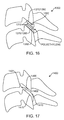
- FIG. 16 shows correction of cervical stenosis or other ailment with a further embodiment of the implant of the invention, comprising two facet implants with articular inner surfaces.
- FIG. 17 shows correction of cervical stenosis or other ailment with a further embodiment of the implant of the invention, comprising a facet joint implant with a roller.
- FIG. 18 shows correction of cervical stenosis or other ailment with a further embodiment of the implant of the invention, comprising a facet joint implant with a plurality of rollers.
- FIG. 19 shows correction of cervical stenosis or other ailment with a further embodiment of the implant of the invention, comprising two facet joint implants, screw fixation, and elastic restraint.
- FIG. 20 shows correction of cervical stenosis or other ailment with a further embodiment of the implant of the invention, comprising two facet joint implants, screw fixation, and spring restraint.
- FIG. 21 shows correction of cervical stenosis or other ailment with a further embodiment of the implant of the invention, comprising two facet joint implants, screw fixation, and magnetic restraint.
- FIG. 22A shows a perspective view of a further embodiment of implant of the invention.
- FIG. 22B shows a perspective exploded view of the embodiment of the invention shown in FIG. 22A .
- FIG. 23A depicts a posterior view of the embodiment of the implant of the invention shown in FIG. 22A .
- FIG. 23B shows a posterior view of a locking plate of the embodiment of the implant of the invention shown in FIG. 22A .
- FIG. 24A depicts a lateral side view of the embodiment of the implant of the invention shown in FIG. 22A .
- FIG. 24B shows a lateral side view of the keel of the locking plate of the embodiment of the implant of the invention shown in FIG. 22A .
- FIG. 25A shows a perspective view of a further embodiment of the implant of the invention.
- FIG. 25B shows a side view of the embodiment of the implant of the invention in FIG. 25A , having a curved, uniformly-thick artificial facet joint spacer or inter-facet spacer including a tapered end.
- FIG. 26A shows an anterior perspective view of a further embodiment of the implant of the invention.
- FIG. 26B shows a posterior perspective view of the embodiment of the implant of the invention depicted in FIG. 26A .
- FIG. 27A depicts a side view of the embodiment of the implant of the invention shown in FIGS. 26A and 26B , implanted in the cervical spine.
- FIG. 27B shows a posterior view of the embodiment of the implant of the invention shown in FIGS. 26A , 26 B, and 27 A, implanted in the cervical spine.
- FIG. 28A depicts a posterior perspective view of a further embodiment of the implant of the invention.
- FIG. 28B depicts a side view of the embodiment of the implant of the invention shown in FIG. 28A .
- FIG. 29A depicts a side view of an embodiment of a sizing tool of the invention.
- FIG. 29B depicts a top view of an embodiment of the sizing tool of the invention depicted in FIG. 29A .
- FIG. 29C depicts a perspective view of an embodiment of the sizing tool of the invention depicted in FIGS. 29A-B .
- FIG. 29D depicts a side view of the head of the sizing tool of the invention depicted in FIG. 29A
- FIG. 29E depicts a cross-sectional view of the head of the sizing tool of the invention depicted in FIGS. 29A-C .
- FIG. 30 is a flow diagram of an embodiment of a method of the invention.
- Embodiments of the present invention provide for a minimally invasive surgical implantation method and apparatus for cervical spine implants that preserves the physiology of the spine.
- embodiments provide for distracting the cervical spine to increase the foraminal dimension in extension and neutral positions.
- Such implants distract, or increase the space between, the vertebrae to increase the foraminal area or dimension, and reduce pressure on the nerves and blood vessels of the cervical spine.
- an implanted interfacet spacer of 1.5 mm to 2.5 mm in width can result in interfacet distraction that increases foraminal dimension in extension and neutral.
- Other interfacet spacer dimensions also are contemplated by the invention described herein below.
- the present embodiments also preserve mobility of the facet joints.
- Embodiments of the present invention accommodate the distinct anatomical structures of the spine, minimize further trauma to the spine, and obviate the need for invasive methods of surgical implantation.
- Embodiments of the present invention also address spinal conditions that are exacerbated by spinal extension.
- FIG. 1 shows a simplified diagram of a portion of the cervical spine, focusing on a cervical facet joint 1 formed between two adjacent cervical vertebrae.
- the spinous processes 3 are located posteriorly and the vertebral bodies 5 are located anteriorly, and a nerve root canal 7 is visible.
- FIG. 2 depicts cervical foraminal stenosis. From the drawing, the nerve root canal 7 is narrowed relative to the nerve root canal 7 depicted in FIG. 1 .
- the spinal canal and/or intervertebral foraminal also can be narrowed by stenosis. The narrowing can cause compression of the spinal cord and nerve roots.
- FIG. 3A shows a first embodiment 100 of the present invention, which is meant to distract at least one facet joint, in order to increase the dimension of the neural foramen while retaining facet joint mobility.
- the wedge-shaped embodiment or inter-facet spacer 100 is a wedge-shaped implant that can be positioned in the cervical facet joint 101 to distract the joint and reverse narrowing of the nerve root canal 107 .
- the implant is positioned with the narrow portion of the wedge facing anteriorly.
- implants in accordance with the present invention, and/or portions thereof can be fabricated from somewhat flexible and/or deflectable material.
- the implant and/or portions thereof can be made out of a polymer, such as a thermoplastic.
- the implant can be made from polyketone, known as polyetheretherketone (“PEEK”).
- PEEK polyetheretherketone
- the implant can be made from PEEK 450G, which is an unfilled PEEK approved for medical implantation available from Victrex of Lancashire, Great Britain. Other sources of this material include Gharda located in Panoli, India.
- PEEK has the following approximate properties:
- the material specified has appropriate physical and mechanical properties and is suitable for carrying and spreading a physical load between the adjacent spinous processes.
- the implant and/or portions thereof can be formed by extrusion, injection, compression molding and/or machining techniques.
- the implant can comprise, at least in part, titanium or stainless steel, or other suitable implant material which is radiopaque, and at least in part a radiolucent material that does not show up under x-ray or other type of imaging.
- the physician can have a less obstructed view of the spine under imaging, than with an implant comprising radiopaque materials entirely.
- the implant need not comprise any radiolucent materials.
- the material selected also can be filled.
- other grades of PEEK are also available and contemplated, such as 30% glass-filled or 30% carbon-filled, provided such materials are cleared for use in implantable devices by the FDA, or other regulatory body.
- Glass-filled PEEK reduces the expansion rate and increases the flexural modulus of PEEK relative to that unfilled PEEK.
- the resulting product is known to be ideal for improved strength, stiffness, or stability.
- Carbon-filled PEEK is known to enhance the compressive strength and stiffness of PEEK and to decrease its expansion rate. Carbon-filled PEEK offers wear resistance and load-carrying capability.
- the implant is manufactured from PEEK, available from Victrex.
- PEEK polyetherketoneketone
- the spacer also can be comprised of polyetherketoneketone (“PEKK”).
- PEKK polyetherketoneketone
- Other material that can be used include polyetherketone (“PEK”), polyetherketoneetherketoneketone (“PEKEKK”), and polyetheretherketoneketone (“PEEKK”), and generally a polyaryletheretherketone.
- the embodiment 200 of the implant has a joint insert or inter-facet insert 210 , also herein referred to as an artificial facet joint spacer or inter-facet spacer, that is positioned in the cervical facet joint 101 .
- the joint insert or inter-facet spacer 210 can be wedge-shaped with the narrow part of the wedge facing anteriorly.
- the joint insert or inter-facet spacer 210 need not be wedge-shaped but can be of substantially uniform thickness, the thickness determined by an individual patient's need for distraction of the cervical facet joint 201 .
- one objective of this embodiment is facet joint distraction, and joint mobility after implantation.
- the joint insert or inter-facet spacer 210 is continuous with a posterior sheath 220 bent at an angle from the joint insert or inter-facet spacer 210 to align substantially parallel with the bone.
- the posterior sheath can lie against the lamina, preferably against the lateral mass.
- the posterior sheath 220 can have a bore 230 which can accept a bone screw 240 .
- the bore 230 can accept any other appropriate and/or equivalent fixation device capable of fixing the embodiment 200 to the spine.
- the device is thereby affixed to the vertebra, preferably by fixing to the lateral mass.
- FIG. 5 shows embodiment 300 , which is the use of two embodiments 200 , each fixed to one of two adjacent cervical vertebrae.
- the implanted facet joint is distracted and joint mobility is retained.
- a joint insert or inter-facet spacer 310 from each of the two implants is inserted and positioned in the cervical facet joint 301 .
- the joint inserts or inter-facet spacers 310 are substantially flat and parallel to each other and are not wedge-shaped.
- the joint inserts or inter-facet spacers 310 can together define a wedge-shaped insert that is appropriate for the patient.
- the two joint inserts or inter-facet spacers 310 combined can have, by way of example, the shape of the joint insert or inter-facet spacer 210 in FIG. 4 .
- Embodiment 300 then can be fixed to the spine with a screw 340 or any other appropriate fixation device, inserted through a bore 330 in the posterior sheath 320 .
- the posterior sheath 320 can be threaded to accept a screw.
- the screw can be embedded in the lamina, preferably in the lateral mass, where possible.
- FIG. 6 depicts a cervical spine lordosis.
- FIG. 7 demonstrates an embodiment 400 which contemplates positioning two implants to correct for this spinal abnormality while retaining facet joint mobility.
- the joint insert or inter-facet spacer 410 of each implant is shaped so that it is thicker at its anterior portion.
- the implants can be shaped to be thicker at the posterior ends, for example as depicted in FIG. 3A .
- each implant is bent at an angle from the joint insert or inter-facet spacer 410 to be positioned adjacent to the lateral mass and/or lamina, and has a bore 430 to accept a screw 440 or other appropriate and/or equivalent fixation means to fix the embodiment 400 to the spine, preferably to the lateral mass.
- the placement of two joint inserts or inter-facet spacers 410 in the cervical facet joint 401 distracts the facet joint, which shifts and maintains the vertebrae into a more anatomical position to preserve the physiology of the spine.
- FIG. 8 shows a further embodiment 500 of the implant of the invention, wherein the joint insert or inter-facet spacer 510 has a keel 550 on an underside of the joint insert or inter-facet spacer 510 .
- the keel 550 can be made of the same material or materials set forth above. The surfaces of the keel 550 can be roughened in order to promote bone ingrowth to stabilize and fix the implant 500 .
- the keel 550 can be coated with materials that promote bone growth such as, for example, bone morphogenic protein (“BMP”), or structural materials such as hyaluronic acid “HA,” or other substances which promote growth of bone relative to and into the keel 550 .
- BMP bone morphogenic protein
- HA hyaluronic acid
- the keel 550 can be embedded in the facet bone, to facilitate implant retention.
- the keel 550 can be placed into a channel in the facet bone.
- the channel can be pre-cut.
- Teeth (not shown), preferably positioned posteriorly, also may be formed on the keel 550 for facilitating retention of the implant 500 in the cervical facet joint 501 .
- the joint insert or inter-facet spacer 510 can be substantially flat or wedge-shaped, depending upon the type of distraction needed, i.e., whether distraction is also necessary to correct abnormal curvature or lack of curvature in the cervical spine. Because the joint is not fused, mobility is retained, as with the embodiments described above and herein below.
- FIG. 9 illustrates that a further embodiment 600 of the implant of the invention can have both screw fixation and a keel 650 for stability and retention of the implant 600 .
- the joint insert or inter-facet spacer 610 is continuous with a posterior sheath 620 having a bore hole 630 to accept a screw 640 which passes through the bore 630 and into the bone of the vertebrae, preferably into the lateral mass, or the lamina.
- the bore 630 can be threaded or not threaded where it is to accept a threaded screw or equivalent device. Alternatively, the bore 630 need not be threaded to accept a non-threaded equivalent device.
- the keel 650 is connected with the joint insert or inter-facet spacer 610 and embeds in the bone of the cervical facet joint 601 to promote implant retention.
- FIG. 10 A further alternative embodiment 700 is illustrated in FIG. 10 .
- the joint insert or inter-facet spacer 710 has on a lower side at least one tooth 760 .
- a plurality of teeth 760 is preferable.
- the teeth 760 are able to embed in the bone of the cervical facet joint 701 to facilitate retention of the implant 700 in the joint 701 .
- the teeth 760 can face in a direction substantially opposite the direction of insertion, for retention of the implant 700 .
- the joint insert or inter-facet spacer 710 can be wedge-shaped or substantially even in thickness, depending upon the desired distraction. Because the implant distracts and is retained without fusion, facet joint mobility is retained.
- FIG. 11 depicts a further embodiment 800 of the implant of the invention.
- the joint insert or inter-facet spacer 810 is continuous with a posterior sheath 820 having a bore 830 for accepting a fixation device 840 , as described above.
- the fixation device 840 can be a screw which fits into a threaded bore 830 ; alternatively, the fixation device 830 can be any other compatible and appropriate device.
- This embodiment 800 further combines at least one tooth 860 on an underside of the joint insert or inter-facet spacer 810 with the posterior sheath 820 , bore 830 and fixation device 840 to address fixation of the implant 800 in a cervical facet joint 801 .
- the implant 800 can have a plurality of teeth 860 on the underside of the joint insert or inter-facet spacer 810 .
- FIG. 12 shows yet another embodiment 900 of an implant of the present invention.
- the joint inserts or inter-facet spacers 910 of two implants 900 are positioned in a cervical facet joint 901 .
- the joint inserts or inter-facet spacers 910 can be wedge-shaped as needed to restore anatomical curvature of the cervical spine and to distract, or the joint inserts or inter-facet spacers 910 can be of substantially uniform thickness.
- the implants 900 each comprise a joint insert or inter-facet spacer 910 with an outer surface 970 that interacts with the bone of the cervical facet joint 901 .
- the surface 970 that interacts with the bone is the upper surface 970 and on the lower implant 900 , the surface 970 that interacts with the bone is the lower surface 970 .
- Each surface 970 can comprise a bone ingrowth surface 980 to create a porous surface and thereby promote bone ingrowth and fixation.
- One such treatment can be with plasma spray titanium, and another, with a coating of sintered beads.
- the implant 900 can have casted porous surfaces 970 , where the porous surface is integral to the implant 900 .
- the surfaces 970 can be roughened in order to promote bone ingrowth into these defined surfaces of the implants 900 .
- the surfaces 970 can be coated with materials that promote bone growth such as for example bone morphogenic protein (“BMP”), or structural materials such as hyaluronic acid (“HA”), or other substances which promote growth of bone on other external surfaces 970 of the implant 900 .
- BMP bone morphogenic protein
- HA hyaluronic acid
- FIG. 13 depicts yet another embodiment 1000 of the implant of the present invention.
- the joint inserts or inter-facet spacers 1010 of two implants 1000 are positioned in a cervical facet joint 1001 .
- the joint inserts or inter-facet spacers 1010 can be wedge-shaped as needed to restore anatomical curvature of the cervical spine and to distract, or the joint inserts or inter-facet spacers 1010 can be of substantially uniform thickness.
- the implants 1000 each comprise a joint insert or inter-facet spacer 1010 with an outer surface 1070 that interacts with the bone of the cervical facet joint 1001 .
- each outer surface 1070 can comprise a bone ingrowth surface 1080 to create a porous surface and thereby promote bone ingrowth and fixation, without facet joint fusion and loss of mobility.
- the bone ingrowth surface 1080 can be created with plasma spray titanium, and/or with a coating of sintered beads.
- the implant 1000 can have casted porous surfaces 1070 , where the porous surface is integral to the implant 1000 .
- the surfaces 1070 can be roughened in order to promote bone ingrowth into these defined surfaces of the implants 1000 .
- the surfaces 1070 can be coated with materials that promote bone growth such as for example BMP, or structural materials such as HA, or other substances which promote growth of bone on other external surfaces 1070 of the implant 1000 .
- the implant 1000 can have a posterior alignment guide 1090 .
- the posterior alignment guides 1090 of each implant 1000 can be continuous with the joint inserts or inter-facet spacers 1010 .
- the posterior alignment guides substantially conform to the bone of the vertebrae when the joint inserts or inter-facet spacers 1010 are inserted into the cervical facet joint 1001 .
- the posterior alignment guides 1090 are used to align the implants 1000 so that the joint inserts or inter-facet spacers 1010 contact each other and not the bones of the cervical facet joint 1001 when the joint inserts or inter-facet spacers 1010 are positioned in the cervical facet joint 1001 .
- FIG. 14 depicts a further embodiment 1100 of the implant of the present invention.
- the joint inserts or inter-facet spacers 1110 of two implants 1100 are inserted into the cervical facet joint 1101 .
- Each of the joint inserts or inter-facet spacers 1110 is continuous with a cervical facet joint extender or facet-extending surface 1192 .
- the bone contacting surfaces 1170 of the joint inserts or inter-facet spacers 1110 are continuous with, and at an angle to, the bone contacting surfaces 1193 of the cervical facet joint extenders 1192 , so that the cervical facet joint extenders 1192 conform to the bones of the vertebrae exterior to the cervical facet joint 1101 .
- the conformity of the cervical facet joint extenders 1192 is achieved for example by forming the cervical facet joint extenders 1192 so that when the join inserts or inter-facet spacers 1110 are positioned, the cervical facet joint extenders 1192 curve around the bone outsider the cervical facet joint 1101 .
- the cervical facet joint extenders have a second surface 1184 that is continuous with the joint articular surfaces 1182 of the joint inserts or inter-facet spacers 1110 .
- the second surfaces 1184 extend the implant 1100 posteriorly to expand the joint articular surfaces 1182 and thereby to increase contact and stability of the spine at least in the region of the implants 1100 . It is to be understood that such facet joint extenders 1192 can be added to the other embodiments of the invention described and depicted herein.
- each of two implants 1200 has a joint insert or inter-facet spacer 1210 positioned in a cervical facet joint 1201 .
- the joint inserts or inter-facet spacers 1210 can be wedge-shaped as needed to restore anatomical curvature of the cervical spine and to distract, or the joint inserts or inter-facet spacers 1210 can be of substantially uniform thickness.
- the implants 1200 each comprise a joint insert or inter-facet spacer 1210 with an outer surface 1270 that interacts with the bone of the cervical facet joint 1001 .
- the surface 1270 that interacts with the bone is the upper surface and on the lower implant 1200 , the surface 1270 that interacts with the bone is the lower surface.
- each outer surface 1270 can comprise a bone ingrowth surface 1280 to create a porous surface and thereby promote bone ingrowth and fixation.
- the bone ingrowth surface 1280 can be created with plasma spray titanium, and/or with a coating of sintered beads.
- the implant 1200 can have casted porous surfaces 1270 , where the porous surface is integral to the implant 1200 .
- the surfaces 1270 can be roughened in order to promote bone ingrowth into these defined surfaces of the implants 1200 .
- the surfaces 1270 can be coated with materials that promote bone growth such as for example BMP, or structural materials such as HA, or other substances which promote growth of bone on other external surfaces 1270 of the implant 1200 .
- Screw fixation or other appropriate fixation also can be used with implants 1200 for fixation in the cervical facet joint 1201 .
- the joint insert or inter-facet spacer 1210 is continuous with a posterior sheath 1220 bent at an angle from the joint insert or inter-facet spacer 1210 to align substantially parallel with the bone, preferably the lateral mass or lamina.
- the posterior sheath 1220 can have a bore 1230 which can accept a bone screw 1240 , preferably into the lateral mass or lamina.
- the bore 1230 can accept any other appropriate and/or equivalent fixation means for fixing the embodiment 1200 to the spine.
- FIG. 16 depicts a further preferred embodiment of the present invention.
- two joint inserts or inter-facet spacers 1310 are positioned in the cervical facet joint 1301 .
- the joint inserts or inter-facet spacers each have outer surfaces 1370 that interact with the bone of the vertebrae forming the cervical facet joint.
- These outer surfaces 1370 of the embodiment 1300 can be treated to become bone ingrowth surfaces 1380 , which bone ingrowth surfaces 1380 contribute to stabilizing the two joint inserts or inter-facet spacers 1310 of the implant 1300 .
- the bone ingrowth surface 1380 can be created with plasma spray titanium, and/or with a coating of sintered beads.
- the implant 1300 can have casted porous surfaces 1370 , where the porous surface is integral to the implant 1300 .
- the surfaces 1370 can be roughened in order to promote bone ingrowth into these defined surfaces of the implants 1300 .
- the surfaces 1370 can be coated with materials that promote bone growth such as for example BMP, or structural materials such as HA, or other substances which promote growth of bone on other external surfaces 1370 of the implant 1300 . This fixation stabilizes the implant 1300 in the facet joint without fusing the joint, and thus the implant preserves joint mobility, while accomplishing distraction and increasing foraminal dimension.
- articular inner surfaces 1382 of the implants 1300 can be formed from a metal and polyethylene, the material allowing flexibility and providing for forward bending/flexion and backward extension of the cervical spine.
- the embodiment 1300 of FIG. 16 can be made in at least two configurations.
- the first configuration includes a flexible spacer 1382 made, by way of example, using polyethylene or other suitable, flexible implant material.
- the flexible spacer 1382 can be permanently affixed to the upper and lower joint insert or inter-facet spacer 1310 .
- the spacer 1382 can be flat or wedge-shaped or have any other shape that would correct the curvature of the spine.
- the spacer 1382 can be affixed to only the upper insert or inter-facet spacer 1310 or to only the lower insert or inter-facet spacer 1310 .
- a spacer 1382 can be affixed to each of an upper insert or inter-facet spacer 1310 and a lower insert 1310 with the upper insert or inter-facet spacer 1310 and the lower insert or inter-facet spacer 1310 being separate units.
- FIG. 17 shows a further preferred embodiment of the implant of the present invention.
- the implant has a roller 1496 mounted on a joint insert or inter-facet spacer 1410 , the roller being a further means of preserving joint mobility while accomplishing distraction.
- Both the roller 1496 and the joint insert or inter-facet spacer 1410 are positioned in the cervical facet joint 1401 .
- the joint insert or inter-facet spacer 1410 as in other embodiments has a bone-facing surface 1470 and joint articular surface 1482 .
- the bone-facing surface 1470 can interact with the lower bone of the cervical facet joint 1401 .
- the bone-facing surface can interact with the upper bone of the cervical facet joint 1401 .
- roller 1496 rotates in a cavity in the joint insert or inter-facet spacer 1410 , and interacts with the top bone of the cervical facet joint 1401 .
- the roller 1496 rotates in a cavity in the joint insert or inter-facet spacer 1410 and interacts with the lower bone of the cervical facet joint 1401 .
- the rotation of the roller 1496 allows flexion and extension of the cervical spine.
- a roller such as roller 1496 can be secured to an upper and a lower insert such as inserts 410 in FIG. 7 .
- a plurality of rollers 1496 also is possible.
- FIG. 19 depicts a further embodiment of the implant of the present invention.
- two implants 1500 are implanted in the cervical facet joint 1501 .
- Screw fixation or other appropriate fixation is used with implants 1500 for fixation in the cervical facet joint 1501 .
- the joint insert or inter-facet spacer 1510 is continuous with a posterior sheath 1520 bent at an angle from the joint insert or inter-facet spacer 1510 to align substantially parallel with the bone, preferably the lateral mass or lamina.
- the posterior sheath 1520 of each implant 1500 can have a bore 1530 which can accept a bone screw 1540 , preferably into the lateral mass or lamina.
- the bore 1530 can accept any other appropriate and/or equivalent fixation means for fixing the embodiment 1500 to the spine.
- the head of the screw 1540 in each posterior sheath 1520 of each implant 1500 has a groove 1598 or other mechanism for retaining an elastic band 1597 .
- the elastic band 1597 is looped around each of the two screws 1540 to restrain movement of the cervical spine without eliminating facet joint mobility.
- the band 1597 preferably can restrain flexion and lateral movement.
- the elastic band 1597 can be made of a biocompatible, flexible material.
- FIG. 20 shows an alternative to use of an elastic band as in FIG. 19 .
- the elastic band is replaced with a spring restraint 1699 , which extends between the heads of two screws 1640 , one screw fixing each of two implants 1600 in the cervical facet joint 1601 .
- FIG. 21 shows another alternative to using an elastic band and/or a spring as in FIG. 19 or 20 .
- magnets 1795 are used for restraint between the two screws 1740 .
- the magnet 1795 can either be comprised of two opposing magnetic fields or two of the same magnetic fields to operate to restrain movement.
- the head of one of the two screws 1740 is magnetized, and the head of the other screw 1740 is magnetized with either the same or opposite field. If the magnets 1795 have the same polarity, the magnets 1795 repel each other and thus limit extension. If the magnets 1795 have opposite polarities, the magnets 1795 attract each other and thus limit flexion and lateral movement.
- FIGS. 22A-24B depict a further embodiment 1800 of the implant of the present invention.
- an artificial facet joint spacer (or insert) or inter-facet spacer (or insert) 1810 is connected with a lateral mass plate (also referred to as an anchoring plate) 1820 with a hinge 1822 .
- the hinge 1822 allows the lateral mass plate 1820 to bend at a wide range of angles relative to the artificial facet joint or inter-facet spacer and preferably at an angle of more than 90 degrees, and this flexibility facilitates positioning and insertion of the artificial facet joint spacer or inter-facet spacer 1810 into a patient's facet joint, the anatomy of which can be highly variable among individuals.
- the hinge 1822 further facilitates customizing the anchoring of the implant, i.e., the positioning of a fixation device.
- the hinge enables positioning of the lateral mass plate 1820 to conform to a patient's cervical spinal anatomy, and the lateral mass plate 1820 accepts a fixation device to penetrate the bone.
- the artificial facet joint spacer or inter-facet spacer 1810 can be curved or rounded at a distal end 1812 ( FIG. 23A ), and convex or dome-shaped on a superior surface 1813 to approximate the shape of the bone inside the facet joint.
- the inferior surface 1815 can be flat or planar. Alternatively, the inferior surface 1815 can be concave. As another alternative, the inferior surface 1815 can be convex.
- the lateral mass plate 1820 when implanted in the spine, is positioned outside the facet joint, preferably against the lateral mass or against the lamina.
- the lateral mass plate 1820 has a bore 1830 therethrough.
- the bore 1830 can accept a bone screw 1840 , also referred to as a lateral mass screw, to secure the lateral mass plate 1820 preferably to the lateral mass or alternatively to another part of the spine, and thus to anchor the implant.
- the lateral mass screw 1840 preferably has a hexagonal head to accept an appropriately-shaped wrench. As described below, the head accepts a compatible probe 1826 from a locking plate 1824 .
- the locking plate 1824 includes a keel 1828 with a wedge shaped distal end to anchor the implant, preferably in the lateral mass or in the lamina, outside the facet joint and to prevent rotation of the lateral mass plate 1820 and the locking plate 1824 .
- the keel 1828 aligns with a groove 1823 through an edge of the lateral mass plate 1820 to guide and align the keel 1828 as the keel 1828 cuts into a vertebra.
- the locking plate 1824 includes a probe 1826 that fits against the head of the lateral mass screw 1840 .
- the locking plate further includes a bore 1831 that can accept a machine screw (not shown) which passes through to an aligned bore 1829 in the lateral mass plate 1820 to hold the locking plate 1824 and the lateral mass plate 1820 together without rotational displacement relative to each other.
- the locking plate 1824 thus serves at least two functions: (1) maintaining the position of the lateral mass screw 1840 with the probe 1826 , so that the screw 1840 does not back out; and (2) preventing rotation of the implant with the keel 1828 and machine screw relative to the cervical vertebra or other vertebrae.
- the locking plate 1824 can include a probe with barbs that can be inserted into a port in the lateral mass plate. The barbs can become engaged in ribs that define the side walls of the port in the lateral mass plate.
- the lateral mass plate 1920 includes a recessed area 1922 for receiving the locking plate 1924 so that the locking plate 1924 is flush with the upper surface 1925 of the lateral mass plate 1920 when the probe 1926 is urged against the lateral mass screw 1940 and the keel 1928 is inserted into the lateral mass or the lamina of the vertebra.
- the shape and contours of the artificial facet joint spacer or inter-facet joint spacer 1910 can facilitate insertion of the artificial facet joint spacer or inter-facet joint spacer 1910 into the cervical facet joint.
- the artificial facet joint spacer or inter-facet joint spacer 1910 has a rounded distal end 1912 .
- the distal end 1912 is tapered in thickness to facilitate insertion.
- the tapered distal end 1912 meets and is continuous with a proximal mid-section 1916 which, in this preferred embodiment, has a uniform thickness, and is connected flexibly, preferably with a hinge 1922 , to the lateral mass plate 1920 , as described above.
- the artificial facet joint spacer (or insert) or inter-facet joint spacer (or insert) 1910 is curved downward, causing a superior surface 1913 of the artificial facet joint spacer or inter-facet joint spacer 1910 to be curved.
- the curve can cause the superior surface 1913 to be convex, and the convexity can vary among different implants 1900 to suit the anatomical structure of the cervical facet joint(s) of a patient.
- An inferior surface 1915 accordingly can be preferably concave, flat, or convex.
- the curved shape of the implant can fit the shape of a cervical facet joint, which is comprised of an inferior facet of an upper vertebra and a superior facet of a lower adjacent vertebra.
- the convex shape of the superior surface 1913 of the artificial facet joint spacer or inter-facet joint spacer 1910 fits with a concave shape of the inferior facet of the upper cervical vertebrae.
- the concave shape of the inferior surface 1915 of the artificial facet joint spacer or inter-facet joint spacer 1910 fits with the convex shape of the superior facet of the cervical vertebrae.
- the degree of convexity and concavity of the artificial facet joint inferior and superior surfaces can be varied to fit a patient's anatomy and the particular pairing of adjacent cervical vertebrae to be treated.
- a less-curved artificial facet joint spacer or inter-facet joint spacer 1910 can be used where the patient's cervical spinal anatomy is sized (as described below) and found to have less convexity and concavity of the articular facets. Generally for the same level the input for the right and left facet joint will be similarly shaped. It is expected that the similarity of shape of the artificial facet joint spacer or inter-facet joint spacer and the smooth, flush surfaces will allow distraction of the facet joint without loss of mobility or damage to the bones of the cervical spine. Further, and preferably, the width of the mid-section 1916 is from 1.5 mm to 2.5 mm.
- FIGS. 22A-24B is similar to the embodiment shown in FIGS. 25A , 25 B. Accordingly the remaining elements on the 1900 series of element numbers is preferably substantially similar to the described elements in the 1800 series of element numbers, as set forth above. Thus, by way of example, elements 1923 , 1928 , 1929 and 1930 are similar to respective elements 1823 , 1828 , 1829 and 1830 .
- FIG. 30 is a flow chart of the method of insertion of an implant of the invention.
- the embodiment 1800 or 1900 of the present invention preferably is inserted in the following manner (only elements of the embodiment 1800 will be set forth herein, for purposes of the written description of a method of the invention).
- a sizing tool 2200 (see FIGS. 29A-C ) can be inserted to select the appropriate size of an implant of the invention for positioning in the cervical facet joint. This step may be repeated as necessary with, if desired, different sizes of the tool 2200 until the appropriate size is determined. This sizing step also distracts the facet joint and surrounding tissue in order to facilitate insertion of the implant.
- the artificial facet joint spacer or inter-facet joint spacer 1810 is urged between the facets into the facet joint.
- the facet itself is somewhat shaped like a ball and socket joint. Accordingly, in order to accommodate this shape, the artificial joint spacer or inter-facet joint spacer 1810 can have a rounded leading edge shaped like a wedge or tissue expander to cause distraction of the facet joint as the artificial facet joint spacer or inter-facet joint spacer is urged into the facet joint of the spine.
- the artificial facet joint spacer or inter-facet joint spacer 1810 also includes the convex surface 1813 in order to more fully accommodate the shape of the facet joint of the spine. However, as set forth above and as depicted in FIG.
- the lateral mass plate 1820 is pivoted downward about the hinge 1822 adjacent to the vertebrae and preferably to the lateral mass or to the lamina.
- the lateral mass plate 1820 may be disposed at an angle relative to the artificial facet joint spacer or inter-facet joint spacer 1810 for a representative spine configuration. It is to be understood that as this embodiment is hinged the final position of the lateral mass plate 1820 relative to the artificial facet joint spacer or inter-facet joint spacer 1810 will depend on the actual spine configuration.
- embodiments of the invention can be made without a hinge, as long as the connection between the artificial facet joint spacer or inter-facet joint spacer and the lateral mass plate is flexible enough to allow the lateral mass plate to be bent relative to the artificial facet joint spacer or inter-facet joint spacer in order to fit the anatomy of the patient.
- a bore can be drilled in the bone to accommodate the bone screw 1824 .
- the screw 1824 can be self-tapping.
- the screw is then placed through the bore 1830 and secured to the bone, preferably the lateral mass or the lamina, thereby holding the artificial facet joint spacer or inter-facet joint spacer 1810 in place.
- the locking plate 1824 is positioned over the lateral mass plate 1820 . So positioned, the probe 1826 is positioned through the bore 1830 and against the head of the bone screw to keep the bone screw from moving.
- the keel 1828 having a sharp chisel-shaped end, preferably can self-cut a groove in the bone so that the keel 1828 is locked into the bone as the keel 1828 is aligned by, and received in, a groove 1831 of the lateral mass plate 1820 .
- a groove can be pre-cut in the bone to receive the keel 1828 .
- the bore 1829 of the locking plate 1824 aligns with the threaded bore 1831 of the lateral mass plate 1820 and a machine screw can be inserted to lock the locking plate relative to the lateral mass plate.
- the implant is between the C5 and C6 vertebrae level, or the C6 and C7 vertebrae level. It is noted that two implants preferably will be implanted at each level between vertebrae. That is, an implant 1800 will be placed in a right facet joint and also in a left facet joint when viewed from a posterior view point.
- This procedure can be used to increase or distract the foraminal area or dimension of the spine in an extension or in neutral position (without having a deleterious effect on cervical lordosis) and reduce the pressure on the nerves and blood vessels. At the same time this procedure preserves mobility of the facet joint.
- FIGS. 26A-27B show a further embodiment of the implant of the invention, with the embodiment 2000 implanted in the cervical spine as depicted in FIGS. 27A and 27B .
- the implant 2000 comprises a first artificial facet joint spacer (or insert) or inter-facet joint spacer (or insert) 2010 and a second artificial facet joint spacer (or insert) or inter-facet joint spacer (or insert) 2010 .
- Each artificial facet joint spacer or inter-facet joint spacer can have a distal end 2012 that is tapered or wedge-shaped in a way that facilitates insertion into the cervical facet joints on both sides of two adjacent cervical vertebrae at the same level.
- the artificial facet joint spacers or inter-facet joint spacers further can be dome-shaped, or convex on a superior surface 2013 , to approximate the shape of the cervical facets of the cervical facet joints.
- the first and second artificial facet joint spacers or inter-facet joint spacers 2010 are bridged together by a collar 2015 .
- the collar 2015 passes between the spinous processes of the adjacent cervical vertebrae.
- the implant can preferably be “V” shaped or “boomerang” shaped.
- the entire implant 2000 or the collar 2015 of the implant can be made of a flexible material such as titanium, so that it is possible to bend the collar 2015 so that it conforms preferably to the shape of the lateral mass or the lamina of the cervical vertebrae of the patient and thereby holds the implant in place with the artificial facet joint spacers or inter-facet joint spacers 2010 inserted in the cervical facet joints.
- Bores 2029 are preferably are provided through implant 2000 adjacent to the artificial facet joint spacer or inter-facet joint spacer 2010 respectively. These bores 2029 can receive bone screws to position the implant 2000 against the lateral mass or the lamina as shown in FIGS. 27A , 27 B.
- the description of the embodiment 2100 , in FIGS. 28A , 28 B provide further details concerning the method of affixing the implant 2000 to the vertebrae.
- the implant 2100 also can be made of PEEK or other materials as described herein.
- Embodiment 2000 (the “boomerang” shape depicted in FIG. 27B ) further can have a locking plate as, for example, the locking plate 1824 in FIG. 22A .
- the locking plate for embodiment 2000 can have the same features as locking plate 1824 , that is: (1) a probe 1826 that interacts with the bone screws to prevent the bone screws from backing out of the bone, the likely consequence of which would be displacement of the implant 2000 ; and (2) a keel 1828 with a chisel end to embed in the bone and thus to prevent rotational displacement of the implant.
- a chisel may not serve the same purpose as with the embodiments set forth above, which lack a collar stabilized by two bone screws. Therefore, a locking plate on embodiment 2000 can be provided without a keel.
- FIGS. 28A and 28B depict a further embodiment of the implant of the invention 2100 .
- the collar 2115 can be made of a flexible material such as titanium, of a substantially inflexible material, or of other materials described herein. Substantial flexibility can also be derived from connecting a first artificial facet joint spacer (or insert) or inter-facet joint spacer (or insert) 2110 with the collar 2115 using a first hinge 2117 , and connecting a second artificial facet joint spacer or inter-facet spacer 2110 with the collar 2115 using a second hinge 2117 . Using the first hinge 2117 and the second hinge 2117 , the collar 2115 can be pivoted downward to conform to a particular patient's cervical spinal anatomy. In other words, the degree of pivoting will vary among different patients, and the first hinge 2117 and second hinge 2117 allow the implant 2100 to accommodate the variance.
- the collar 2115 can have a first bore 2129 inferior to the first hinge 2117 , and a second bore 2129 inferior to the second hinge 2117 .
- a first bone screw penetrates the first bore 2130 and into the lateral mass or the lamina
- the second bone screw penetrates the second bore 2130 and into the lateral mass or the lamina, the first and second bone screws serving to anchor the implant.
- a bore, preferably in the lateral mass, can be drilled for the first bone screw and for the second bone screw.
- the bone screws can be self-tapping.
- a first locking plate similar to the plate 1924 ( FIG.
- the first locking plate can block the first bone screw with a probe and the second locking plate can block to the second bone screw with a probe.
- embodiments 2000 and 2100 also can be configured for accommodating treatment of cervical spinal stenosis and other cervical spine ailments where only a single cervical facet joint between adjacent vertebrae requires an implant, i.e., where treatment is limited to one lateral facet joint.
- the collar 2015 , 2115 extends medially without extending further to join a second artificial facet joint spacer or inter-facet joint spacer 2010 , 2110 .
- the implant comprises a single hinge 2117 , and the collar 2115 has only one bore 2129 to accept one bone screw to secure the implant 2100 .
- FIGS. 29A-E depict a sizing and distracting tool 2200 of the invention.
- Sizing tool 2200 has a handle 2203 and a distal head 2210 that is shaped as an artificial facet joint spacer or inter-facet joint spacer (e.g., 1810 ) of an implant of the invention. That is, the head 2210 preferably will have essentially the same features as the artificial facet joint spacer and inter-facet joint spacer 1810 , but the dimensions of the head 2210 will vary from one tool 2200 to the next, in order to be able to use different versions of the sizing tool 2200 to determine the dimensions of the cervical facet joint that is to be treated and then to select an appropriately-sized implant.
- an artificial facet joint spacer or inter-facet joint spacer e.g. 1810
- the head 2210 preferably can be used to distract the facet joint prior to the step of implanting the implant in the facet joint.
- the head 2210 is rounded at the most distal point 2212 , and can be a tapered to facilitate insertion into a cervical facet joint.
- the head 2210 also can have a slightly convex superior surface 2213 , the degree of convexity varying among different sizing tools 2200 in order to determine the desired degree of convexity of an implant to be implanted in the cervical facet joint.
- the head 2210 may have a uniform thickness along a proximal mid-section 2216 .
- the inferior surface 2215 preferably can be concave.
- the proximal mid-section 2212 may be convex on the superior surface 1813 without being uniform in thickness.
- the inferior surface 2215 can be flat or planar.
- the head also can be curved.
- the head 2210 has a stop 2218 to prevent over-insertion of the head 2210 of the sizing tool 2200 into the facet joint.
- the stop 2218 can be a ridge that separates the head 2210 from the handle 2203 .
- the stop 2218 can be any structure that prevents insertion beyond the stop 2218 , including pegs, teeth, and the like.
- Different sizing tools 2200 covering a range of dimensions of the head 2210 can be inserted successively into a cervical facet joint to select the appropriate size of an implant to position in the cervical spine, with the appropriate convexity and concavity of artificial facet joint.
- Each preferably larger head also can be used to distract the facet joint.
Abstract
Description
| Property | Value | ||
| Density | 1.3 | g/cc | ||
| Rockwell M | 99 | |||
| Rockwell R | 126 | |||
| Tensile Strength | 97 | MPa | ||
| Modulus of Elasticity | 3.5 | GPa | ||
| Flexural Modulus | 4.1 | GPa | ||
Claims (30)
Priority Applications (18)
| Application Number | Priority Date | Filing Date | Title |
|---|---|---|---|
| US11/053,624 US7601170B2 (en) | 2004-12-13 | 2005-02-08 | Inter-cervical facet implant and method |
| US11/053,735 US7776090B2 (en) | 2004-12-13 | 2005-02-08 | Inter-cervical facet implant and method |
| US11/053,399 US7591851B2 (en) | 2004-12-13 | 2005-02-08 | Inter-cervical facet implant and method |
| US11/053,346 US20060149289A1 (en) | 2004-12-13 | 2005-02-08 | Inter-cervical facet implant and method |
| JP2007546816A JP2008522787A (en) | 2004-12-13 | 2005-12-13 | Intervertebral implant |
| CA002590049A CA2590049A1 (en) | 2004-12-13 | 2005-12-13 | Inter-facet implant |
| AU2005316646A AU2005316646B2 (en) | 2004-12-13 | 2005-12-13 | Inter-facet implant |
| PCT/US2005/044979 WO2006065774A1 (en) | 2004-12-13 | 2005-12-13 | Inter-facet implant |
| KR1020077016201A KR20070108151A (en) | 2004-12-13 | 2005-12-13 | Inter-facet implant |
| MX2007006808A MX2007006808A (en) | 2004-12-13 | 2005-12-13 | Inter-facet implant. |
| EP05853807A EP1824427A4 (en) | 2004-12-13 | 2005-12-13 | Inter-facet implant |
| US11/304,437 US8128660B2 (en) | 2004-12-13 | 2005-12-14 | Inter-cervical facet joint implant with locking screw system |
| US11/304,202 US8066749B2 (en) | 2004-12-13 | 2005-12-14 | Implant for stabilizing a bone graft during spinal fusion |
| US11/304,436 US20060247633A1 (en) | 2004-12-13 | 2005-12-14 | Inter-cervical facet implant with surface enhancements |
| US11/304,271 US20060247650A1 (en) | 2004-12-13 | 2005-12-14 | Inter-cervical facet joint fusion implant |
| US11/304,404 US8172877B2 (en) | 2004-12-13 | 2005-12-14 | Inter-cervical facet implant with surface enhancements |
| US11/447,413 US8118838B2 (en) | 2004-12-13 | 2006-06-06 | Inter-cervical facet implant with multiple direction articulation joint and method for implanting |
| IL182915A IL182915A0 (en) | 2004-12-13 | 2007-05-01 | Inter-facet implant |
Applications Claiming Priority (5)
| Application Number | Priority Date | Filing Date | Title |
|---|---|---|---|
| US63545304P | 2004-12-13 | 2004-12-13 | |
| US11/053,624 US7601170B2 (en) | 2004-12-13 | 2005-02-08 | Inter-cervical facet implant and method |
| US11/053,346 US20060149289A1 (en) | 2004-12-13 | 2005-02-08 | Inter-cervical facet implant and method |
| US11/053,399 US7591851B2 (en) | 2004-12-13 | 2005-02-08 | Inter-cervical facet implant and method |
| US11/053,735 US7776090B2 (en) | 2004-12-13 | 2005-02-08 | Inter-cervical facet implant and method |
Related Parent Applications (1)
| Application Number | Title | Priority Date | Filing Date |
|---|---|---|---|
| US11/053,346 Continuation-In-Part US20060149289A1 (en) | 2004-12-13 | 2005-02-08 | Inter-cervical facet implant and method |
Related Child Applications (6)
| Application Number | Title | Priority Date | Filing Date |
|---|---|---|---|
| US11/053,624 Continuation-In-Part US7601170B2 (en) | 2004-12-13 | 2005-02-08 | Inter-cervical facet implant and method |
| US11/304,271 Continuation-In-Part US20060247650A1 (en) | 2004-12-13 | 2005-12-14 | Inter-cervical facet joint fusion implant |
| US11/304,404 Continuation-In-Part US8172877B2 (en) | 2004-12-13 | 2005-12-14 | Inter-cervical facet implant with surface enhancements |
| US11/304,436 Continuation-In-Part US20060247633A1 (en) | 2004-12-13 | 2005-12-14 | Inter-cervical facet implant with surface enhancements |
| US11/304,437 Continuation-In-Part US8128660B2 (en) | 2004-12-13 | 2005-12-14 | Inter-cervical facet joint implant with locking screw system |
| US11/304,202 Continuation-In-Part US8066749B2 (en) | 2004-12-13 | 2005-12-14 | Implant for stabilizing a bone graft during spinal fusion |
Publications (2)
| Publication Number | Publication Date |
|---|---|
| US20060149374A1 US20060149374A1 (en) | 2006-07-06 |
| US7776090B2 true US7776090B2 (en) | 2010-08-17 |
Family
ID=46321785
Family Applications (4)
| Application Number | Title | Priority Date | Filing Date |
|---|---|---|---|
| US11/053,735 Active 2026-07-24 US7776090B2 (en) | 2004-12-13 | 2005-02-08 | Inter-cervical facet implant and method |
| US11/053,346 Abandoned US20060149289A1 (en) | 2004-12-13 | 2005-02-08 | Inter-cervical facet implant and method |
| US11/053,399 Active 2026-07-18 US7591851B2 (en) | 2004-12-13 | 2005-02-08 | Inter-cervical facet implant and method |
| US11/053,624 Expired - Fee Related US7601170B2 (en) | 2004-12-13 | 2005-02-08 | Inter-cervical facet implant and method |
Family Applications After (3)
| Application Number | Title | Priority Date | Filing Date |
|---|---|---|---|
| US11/053,346 Abandoned US20060149289A1 (en) | 2004-12-13 | 2005-02-08 | Inter-cervical facet implant and method |
| US11/053,399 Active 2026-07-18 US7591851B2 (en) | 2004-12-13 | 2005-02-08 | Inter-cervical facet implant and method |
| US11/053,624 Expired - Fee Related US7601170B2 (en) | 2004-12-13 | 2005-02-08 | Inter-cervical facet implant and method |
Country Status (1)
| Country | Link |
|---|---|
| US (4) | US7776090B2 (en) |
Cited By (105)
| Publication number | Priority date | Publication date | Assignee | Title |
|---|---|---|---|---|
| US20090198339A1 (en) * | 2008-02-06 | 2009-08-06 | Nuvasive, Inc. | Systems and methods for spinal fusion |
| US8012207B2 (en) | 2004-10-20 | 2011-09-06 | Vertiflex, Inc. | Systems and methods for posterior dynamic stabilization of the spine |
| US8088163B1 (en) | 2008-02-06 | 2012-01-03 | Kleiner Jeffrey B | Tools and methods for spinal fusion |
| US8123782B2 (en) | 2004-10-20 | 2012-02-28 | Vertiflex, Inc. | Interspinous spacer |
| USD656610S1 (en) | 2009-02-06 | 2012-03-27 | Kleiner Jeffrey B | Spinal distraction instrument |
| US8167944B2 (en) | 2004-10-20 | 2012-05-01 | The Board Of Trustees Of The Leland Stanford Junior University | Systems and methods for posterior dynamic stabilization of the spine |
| US8257439B2 (en) | 2004-12-22 | 2012-09-04 | Ldr Medical | Intervertebral disc prosthesis |
| US8267999B2 (en) | 2002-11-05 | 2012-09-18 | Ldr Medical | Intervertebral disc prosthesis |
| US8273108B2 (en) | 2004-10-20 | 2012-09-25 | Vertiflex, Inc. | Interspinous spacer |
| US8277488B2 (en) | 2004-10-20 | 2012-10-02 | Vertiflex, Inc. | Interspinous spacer |
| US8292922B2 (en) | 2004-10-20 | 2012-10-23 | Vertiflex, Inc. | Interspinous spacer |
| US8343189B2 (en) | 2007-09-25 | 2013-01-01 | Zyga Technology, Inc. | Method and apparatus for facet joint stabilization |
| US8343219B2 (en) | 2007-06-08 | 2013-01-01 | Ldr Medical | Intersomatic cage, intervertebral prosthesis, anchoring device and implantation instruments |
| US8348979B2 (en) | 2006-12-29 | 2013-01-08 | Providence Medical Technology, Inc. | Cervical distraction method |
| US8366748B2 (en) | 2008-12-05 | 2013-02-05 | Kleiner Jeffrey | Apparatus and method of spinal implant and fusion |
| US8394125B2 (en) | 2009-07-24 | 2013-03-12 | Zyga Technology, Inc. | Systems and methods for facet joint treatment |
| US8409282B2 (en) | 2004-10-20 | 2013-04-02 | Vertiflex, Inc. | Systems and methods for posterior dynamic stabilization of the spine |
| US8425559B2 (en) | 2004-10-20 | 2013-04-23 | Vertiflex, Inc. | Systems and methods for posterior dynamic stabilization of the spine |
| US8465546B2 (en) | 2007-02-16 | 2013-06-18 | Ldr Medical | Intervertebral disc prosthesis insertion assemblies |
| US8613747B2 (en) | 2004-10-20 | 2013-12-24 | Vertiflex, Inc. | Spacer insertion instrument |
| US8623054B2 (en) | 2008-06-06 | 2014-01-07 | Providence Medical Technology, Inc. | Vertebral joint implants and delivery tools |
| US8628574B2 (en) | 2004-10-20 | 2014-01-14 | Vertiflex, Inc. | Systems and methods for posterior dynamic stabilization of the spine |
| US8663293B2 (en) | 2010-06-15 | 2014-03-04 | Zyga Technology, Inc. | Systems and methods for facet joint treatment |
| US8685031B2 (en) | 2009-09-18 | 2014-04-01 | Spinal Surgical Strategies, Llc | Bone graft delivery system |
| US8696707B2 (en) | 2005-03-08 | 2014-04-15 | Zyga Technology, Inc. | Facet joint stabilization |
| US8740948B2 (en) | 2009-12-15 | 2014-06-03 | Vertiflex, Inc. | Spinal spacer for cervical and other vertebra, and associated systems and methods |
| US8771284B2 (en) | 2005-11-30 | 2014-07-08 | Ldr Medical | Intervertebral disc prosthesis and instrumentation for insertion of the prosthesis between the vertebrae |
| US8845726B2 (en) | 2006-10-18 | 2014-09-30 | Vertiflex, Inc. | Dilator |
| US8858635B2 (en) | 2004-02-04 | 2014-10-14 | Ldr Medical | Intervertebral disc prosthesis |
| US8864828B2 (en) | 2004-10-20 | 2014-10-21 | Vertiflex, Inc. | Interspinous spacer |
| US8864654B2 (en) | 2010-04-20 | 2014-10-21 | Jeffrey B. Kleiner | Method and apparatus for performing retro peritoneal dissection |
| US8906028B2 (en) | 2009-09-18 | 2014-12-09 | Spinal Surgical Strategies, Llc | Bone graft delivery device and method of using the same |
| US8945183B2 (en) | 2004-10-20 | 2015-02-03 | Vertiflex, Inc. | Interspinous process spacer instrument system with deployment indicator |
| USD723682S1 (en) | 2013-05-03 | 2015-03-03 | Spinal Surgical Strategies, Llc | Bone graft delivery tool |
| US8974532B2 (en) | 2004-04-28 | 2015-03-10 | Ldr Medical | Intervertebral disc prosthesis |
| US8979932B2 (en) | 2005-09-23 | 2015-03-17 | Ldr Medical | Intervertebral disc prosthesis |
| US8998968B1 (en) | 2012-11-28 | 2015-04-07 | Choice Spine, Lp | Facet screw system |
| US9011492B2 (en) | 2008-06-06 | 2015-04-21 | Providence Medical Technology, Inc. | Facet joint implants and delivery tools |
| US9039774B2 (en) | 2012-02-24 | 2015-05-26 | Ldr Medical | Anchoring device and system for an intervertebral implant, intervertebral implant and implantation instrument |
| US9039742B2 (en) | 2004-10-20 | 2015-05-26 | The Board Of Trustees Of The Leland Stanford Junior University | Systems and methods for posterior dynamic stabilization of the spine |
| US9044337B2 (en) | 2009-12-31 | 2015-06-02 | Ldr Medical | Anchoring device and system for an intervertebral implant, intervertebral implant and implantation instrument |
| US9060877B2 (en) | 2009-09-18 | 2015-06-23 | Spinal Surgical Strategies, Llc | Fusion cage with combined biological delivery system |
| USD732667S1 (en) | 2012-10-23 | 2015-06-23 | Providence Medical Technology, Inc. | Cage spinal implant |
| US9078765B2 (en) | 2001-07-13 | 2015-07-14 | Ldr Medical | Vertebral cage device with modular fixation |
| US9119680B2 (en) | 2004-10-20 | 2015-09-01 | Vertiflex, Inc. | Interspinous spacer |
| US9149306B2 (en) | 2011-06-21 | 2015-10-06 | Seaspine, Inc. | Spinous process device |
| US9155572B2 (en) | 2004-10-20 | 2015-10-13 | Vertiflex, Inc. | Minimally invasive tooling for delivery of interspinous spacer |
| US9161783B2 (en) | 2004-10-20 | 2015-10-20 | Vertiflex, Inc. | Interspinous spacer |
| US9173694B2 (en) | 2009-09-18 | 2015-11-03 | Spinal Surgical Strategies, Llc | Fusion cage with combined biological delivery system |
| US9186193B2 (en) | 2009-09-18 | 2015-11-17 | Spinal Surgical Strategies, Llc | Fusion cage with combined biological delivery system |
| USD745156S1 (en) | 2012-10-23 | 2015-12-08 | Providence Medical Technology, Inc. | Spinal implant |
| US9211146B2 (en) | 2004-10-20 | 2015-12-15 | The Board Of Trustees Of The Leland Stanford Junior University | Systems and methods for posterior dynamic stabilization of the spine |
| US9233006B2 (en) | 2010-06-15 | 2016-01-12 | Zyga Technology, Inc. | Systems and methods for facet joint treatment |
| US9247943B1 (en) | 2009-02-06 | 2016-02-02 | Kleiner Intellectual Property, Llc | Devices and methods for preparing an intervertebral workspace |
| USD750249S1 (en) | 2014-10-20 | 2016-02-23 | Spinal Surgical Strategies, Llc | Expandable fusion cage |
| US9271742B2 (en) | 2012-08-09 | 2016-03-01 | Wilson Theophilo Asfora | System for joint fusion |
| US9314279B2 (en) | 2004-10-20 | 2016-04-19 | The Board Of Trustees Of The Leland Stanford Junior University | Systems and methods for posterior dynamic stabilization of the spine |
| US9333086B2 (en) | 2008-06-06 | 2016-05-10 | Providence Medical Technology, Inc. | Spinal facet cage implant |
| US9333095B2 (en) | 2001-05-04 | 2016-05-10 | Ldr Medical | Intervertebral disc prosthesis, surgical methods, and fitting tools |
| US9381049B2 (en) | 2008-06-06 | 2016-07-05 | Providence Medical Technology, Inc. | Composite spinal facet implant with textured surfaces |
| US9393055B2 (en) | 2004-10-20 | 2016-07-19 | Vertiflex, Inc. | Spacer insertion instrument |
| US9463091B2 (en) | 2009-09-17 | 2016-10-11 | Ldr Medical | Intervertebral implant having extendable bone fixation members |
| US9622874B2 (en) | 2008-06-06 | 2017-04-18 | Providence Medical Technology, Inc. | Cervical distraction/implant delivery device |
| US9629729B2 (en) | 2009-09-18 | 2017-04-25 | Spinal Surgical Strategies, Llc | Biological delivery system with adaptable fusion cage interface |
| US9675303B2 (en) | 2013-03-15 | 2017-06-13 | Vertiflex, Inc. | Visualization systems, instruments and methods of using the same in spinal decompression procedures |
| US9675389B2 (en) | 2009-12-07 | 2017-06-13 | Samy Abdou | Devices and methods for minimally invasive spinal stabilization and instrumentation |
| US9713535B2 (en) | 2006-02-15 | 2017-07-25 | Ldr Medical | Transforaminal intersomatic cage for an intervertebral fusion graft and an instrument for implanting the cage |
| US9717403B2 (en) | 2008-12-05 | 2017-08-01 | Jeffrey B. Kleiner | Method and apparatus for performing retro peritoneal dissection |
| USD797290S1 (en) | 2015-10-19 | 2017-09-12 | Spinal Surgical Strategies, Llc | Bone graft delivery tool |
| US9833328B2 (en) | 2010-06-15 | 2017-12-05 | Zyga Technology | System and methods for facet joint treatment |
| US9839451B2 (en) | 2016-03-29 | 2017-12-12 | Christopher D. Sturm | Facet joint replacement device and methods of use |
| US9877842B2 (en) | 2014-01-30 | 2018-01-30 | Ldr Medical | Anchoring device for a spinal implant, spinal implant and implantation instrumentation |
| US9937050B2 (en) | 2013-05-16 | 2018-04-10 | Ldr Medical | Vertebral implant, vertebral fastening device of the implant and implant instrumentation |
| US10201375B2 (en) | 2014-05-28 | 2019-02-12 | Providence Medical Technology, Inc. | Lateral mass fixation system |
| USD841165S1 (en) | 2015-10-13 | 2019-02-19 | Providence Medical Technology, Inc. | Cervical cage |
| US10245159B1 (en) | 2009-09-18 | 2019-04-02 | Spinal Surgical Strategies, Llc | Bone graft delivery system and method for using same |
| US10292738B2 (en) | 2004-10-20 | 2019-05-21 | The Board Of Trustees Of The Leland Stanford Junior University | Systems and methods for stabilizing the motion or adjusting the position of the spine |
| USD853560S1 (en) | 2008-10-09 | 2019-07-09 | Nuvasive, Inc. | Spinal implant insertion device |
| US10478310B2 (en) | 2014-05-06 | 2019-11-19 | Ldr Medical, S.A.S. | Vertebral implant, device for vertebral attachment of the implant and instrumentation for implantation thereof |
| US10524772B2 (en) | 2014-05-07 | 2020-01-07 | Vertiflex, Inc. | Spinal nerve decompression systems, dilation systems, and methods of using the same |
| US10548740B1 (en) | 2016-10-25 | 2020-02-04 | Samy Abdou | Devices and methods for vertebral bone realignment |
| US10575961B1 (en) | 2011-09-23 | 2020-03-03 | Samy Abdou | Spinal fixation devices and methods of use |
| US10603185B2 (en) | 2004-02-04 | 2020-03-31 | Ldr Medical | Intervertebral disc prosthesis |
| US10682243B2 (en) | 2015-10-13 | 2020-06-16 | Providence Medical Technology, Inc. | Spinal joint implant delivery device and system |
| USD887552S1 (en) | 2016-07-01 | 2020-06-16 | Providence Medical Technology, Inc. | Cervical cage |
| US10687955B2 (en) | 2018-02-02 | 2020-06-23 | Ayman H. Al-Jazaeri | Distally expanding facet implant with integrated plate and delivery device |
| US10695105B2 (en) | 2012-08-28 | 2020-06-30 | Samy Abdou | Spinal fixation devices and methods of use |
| US10857003B1 (en) | 2015-10-14 | 2020-12-08 | Samy Abdou | Devices and methods for vertebral stabilization |
| US10918498B2 (en) | 2004-11-24 | 2021-02-16 | Samy Abdou | Devices and methods for inter-vertebral orthopedic device placement |
| USD911525S1 (en) | 2019-06-21 | 2021-02-23 | Providence Medical Technology, Inc. | Spinal cage |
| US10973656B2 (en) | 2009-09-18 | 2021-04-13 | Spinal Surgical Strategies, Inc. | Bone graft delivery system and method for using same |
| US10973648B1 (en) | 2016-10-25 | 2021-04-13 | Samy Abdou | Devices and methods for vertebral bone realignment |
| US11000384B2 (en) | 2019-10-15 | 2021-05-11 | Ayman H. Al-Jazaeri | Distally expanding facet joint implant and delivery device |
| US11006982B2 (en) | 2012-02-22 | 2021-05-18 | Samy Abdou | Spinous process fixation devices and methods of use |
| US11065039B2 (en) | 2016-06-28 | 2021-07-20 | Providence Medical Technology, Inc. | Spinal implant and methods of using the same |
| USD933230S1 (en) | 2019-04-15 | 2021-10-12 | Providence Medical Technology, Inc. | Cervical cage |
| US11173040B2 (en) | 2012-10-22 | 2021-11-16 | Cogent Spine, LLC | Devices and methods for spinal stabilization and instrumentation |
| US11179248B2 (en) | 2018-10-02 | 2021-11-23 | Samy Abdou | Devices and methods for spinal implantation |
| US11224521B2 (en) | 2008-06-06 | 2022-01-18 | Providence Medical Technology, Inc. | Cervical distraction/implant delivery device |
| USD945621S1 (en) | 2020-02-27 | 2022-03-08 | Providence Medical Technology, Inc. | Spinal cage |
| US11272964B2 (en) | 2008-06-06 | 2022-03-15 | Providence Medical Technology, Inc. | Vertebral joint implants and delivery tools |
| US11559408B2 (en) | 2008-01-09 | 2023-01-24 | Providence Medical Technology, Inc. | Methods and apparatus for accessing and treating the facet joint |
| US11648128B2 (en) | 2018-01-04 | 2023-05-16 | Providence Medical Technology, Inc. | Facet screw and delivery device |
| US11666455B2 (en) | 2009-09-18 | 2023-06-06 | Spinal Surgical Strategies, Inc., A Nevada Corporation | Bone graft delivery devices, systems and kits |
| US11871968B2 (en) | 2017-05-19 | 2024-01-16 | Providence Medical Technology, Inc. | Spinal fixation access and delivery system |
Families Citing this family (92)
| Publication number | Priority date | Publication date | Assignee | Title |
|---|---|---|---|---|
| US8771365B2 (en) | 2009-02-25 | 2014-07-08 | Conformis, Inc. | Patient-adapted and improved orthopedic implants, designs, and related tools |
| US8735773B2 (en) | 2007-02-14 | 2014-05-27 | Conformis, Inc. | Implant device and method for manufacture |
| US8617242B2 (en) | 2001-05-25 | 2013-12-31 | Conformis, Inc. | Implant device and method for manufacture |
| US8480754B2 (en) | 2001-05-25 | 2013-07-09 | Conformis, Inc. | Patient-adapted and improved articular implants, designs and related guide tools |
| US8882847B2 (en) | 2001-05-25 | 2014-11-11 | Conformis, Inc. | Patient selectable knee joint arthroplasty devices |
| US9603711B2 (en) | 2001-05-25 | 2017-03-28 | Conformis, Inc. | Patient-adapted and improved articular implants, designs and related guide tools |
| US8545569B2 (en) | 2001-05-25 | 2013-10-01 | Conformis, Inc. | Patient selectable knee arthroplasty devices |
| US8556983B2 (en) | 2001-05-25 | 2013-10-15 | Conformis, Inc. | Patient-adapted and improved orthopedic implants, designs and related tools |
| JP2005504563A (en) * | 2001-05-25 | 2005-02-17 | イメージング セラピューティクス,インコーポレーテッド | Methods and compositions for resurfacing joints |
| EP1555962B1 (en) | 2002-10-07 | 2011-02-09 | Conformis, Inc. | Minimally invasive joint implant with 3-dimensional geometry matching the articular surfaces |
| JP2006505366A (en) | 2002-11-07 | 2006-02-16 | コンフォーミス・インコーポレイテッド | Method of determining meniscus size and shape and devised treatment |
| US7588590B2 (en) | 2003-12-10 | 2009-09-15 | Facet Solutions, Inc | Spinal facet implant with spherical implant apposition surface and bone bed and methods of use |
| US8562649B2 (en) | 2004-02-17 | 2013-10-22 | Gmedelaware 2 Llc | System and method for multiple level facet joint arthroplasty and fusion |
| US8333789B2 (en) | 2007-01-10 | 2012-12-18 | Gmedelaware 2 Llc | Facet joint replacement |
| US7588578B2 (en) | 2004-06-02 | 2009-09-15 | Facet Solutions, Inc | Surgical measurement systems and methods |
| US7935134B2 (en) * | 2004-10-20 | 2011-05-03 | Exactech, Inc. | Systems and methods for stabilization of bone structures |
| US8162985B2 (en) | 2004-10-20 | 2012-04-24 | The Board Of Trustees Of The Leland Stanford Junior University | Systems and methods for posterior dynamic stabilization of the spine |
| US8226690B2 (en) | 2005-07-22 | 2012-07-24 | The Board Of Trustees Of The Leland Stanford Junior University | Systems and methods for stabilization of bone structures |
| US8267969B2 (en) | 2004-10-20 | 2012-09-18 | Exactech, Inc. | Screw systems and methods for use in stabilization of bone structures |
| US8025680B2 (en) | 2004-10-20 | 2011-09-27 | Exactech, Inc. | Systems and methods for posterior dynamic stabilization of the spine |
| US20070016196A1 (en) * | 2005-05-10 | 2007-01-18 | Winslow Charles J | Inter-cervical facet implant with implantation tool |
| US20060241758A1 (en) * | 2005-04-20 | 2006-10-26 | Sdgi Holdings, Inc. | Facet spacers |
| US8070749B2 (en) | 2005-05-12 | 2011-12-06 | Stern Joseph D | Revisable anterior cervical plating system |
| US8523865B2 (en) | 2005-07-22 | 2013-09-03 | Exactech, Inc. | Tissue splitter |
| US20070083200A1 (en) * | 2005-09-23 | 2007-04-12 | Gittings Darin C | Spinal stabilization systems and methods |
| EP1951158A4 (en) * | 2005-11-21 | 2010-03-31 | Vertegen Inc | Devices and methods for treating facet joints, uncovertebral joints, costovertebral joints and other joints |
| DE202005019487U1 (en) * | 2005-12-13 | 2007-04-26 | Deru Gmbh | Facet joint prosthesis |
| GB0604061D0 (en) * | 2006-03-01 | 2006-04-12 | Invibio Ltd | Polymetric materials |
| US20070250166A1 (en) * | 2006-04-25 | 2007-10-25 | Sdgi Holdings, Inc. | Facet fusion implants and methods of use |
| US20080177390A1 (en) * | 2006-10-24 | 2008-07-24 | St. Francis Medical Technologies, Inc. | Disk Replacement Endoprosthesis |
| US8096996B2 (en) | 2007-03-20 | 2012-01-17 | Exactech, Inc. | Rod reducer |
| US8974496B2 (en) | 2007-08-30 | 2015-03-10 | Jeffrey Chun Wang | Interspinous implant, tools and methods of implanting |
| US8133261B2 (en) | 2007-02-26 | 2012-03-13 | Depuy Spine, Inc. | Intra-facet fixation device and method of use |
| US8894685B2 (en) | 2007-04-13 | 2014-11-25 | DePuy Synthes Products, LLC | Facet fixation and fusion screw and washer assembly and method of use |
| US8197513B2 (en) | 2007-04-13 | 2012-06-12 | Depuy Spine, Inc. | Facet fixation and fusion wedge and method of use |
| US8043334B2 (en) | 2007-04-13 | 2011-10-25 | Depuy Spine, Inc. | Articulating facet fusion screw |
| US7892267B2 (en) * | 2007-08-03 | 2011-02-22 | Zimmer Spine, Inc. | Attachment devices and methods for spinal implants |
| US8496693B2 (en) * | 2007-10-16 | 2013-07-30 | Amendia Inc. | Bone screw retaining and removal system |
| EP2228042A1 (en) * | 2007-12-28 | 2010-09-15 | Takiron Co., Ltd. | Biomaterial for artificial cartilages |
| US20090177237A1 (en) * | 2008-01-04 | 2009-07-09 | Spartek Medical, Inc. | Cervical spine implant system and method |
| WO2009111656A1 (en) * | 2008-03-05 | 2009-09-11 | Conformis, Inc. | Edge-matched articular implant |
| US8682052B2 (en) | 2008-03-05 | 2014-03-25 | Conformis, Inc. | Implants for altering wear patterns of articular surfaces |
| WO2009111632A1 (en) * | 2008-03-06 | 2009-09-11 | Synthes Usa, Llc | Facet interference screw |
| US8202299B2 (en) | 2008-03-19 | 2012-06-19 | Collabcom II, LLC | Interspinous implant, tools and methods of implanting |
| EP2303193A4 (en) | 2008-05-12 | 2012-03-21 | Conformis Inc | Devices and methods for treatment of facet and other joints |
| US20100030337A1 (en) * | 2008-08-04 | 2010-02-04 | Nasser Ani | Spine Surgery Technique And System |
| WO2010065277A1 (en) * | 2008-11-25 | 2010-06-10 | Synthes Usa, Llc | Visco-elastic facet joint implant |
| WO2010099231A2 (en) | 2009-02-24 | 2010-09-02 | Conformis, Inc. | Automated systems for manufacturing patient-specific orthopedic implants and instrumentation |
| MX2011009401A (en) | 2009-03-13 | 2011-12-14 | Spinal Simplicity Llc | Dynamic vertebral column plate system. |
| US8574270B2 (en) | 2009-03-13 | 2013-11-05 | Spinal Simplicity Llc | Bone plate assembly with bone screw retention features |
| US9204906B2 (en) | 2009-10-22 | 2015-12-08 | Nuvasive, Inc. | Posterior cervical fusion system and techniques |
| US10098674B2 (en) | 2009-10-22 | 2018-10-16 | Nuvasive, Inc. | System and method for posterior cervical fusion |
| EP2509539B1 (en) | 2009-12-11 | 2020-07-01 | ConforMIS, Inc. | Patient-specific and patient-engineered orthopedic implants |
| TWI397394B (en) * | 2009-12-21 | 2013-06-01 | Ind Tech Res Inst | Flexible spine fixing structure |
| US8702758B2 (en) | 2009-12-31 | 2014-04-22 | Industrial Technology Research Institute | Flexible spine fixing structure |
| TWI388308B (en) * | 2009-12-31 | 2013-03-11 | Ind Tech Res Inst | Flexible spine fixing structure |
| WO2012006627A1 (en) | 2010-07-09 | 2012-01-12 | Synthes Usa, Llc | Facet fusion implant |
| US9044277B2 (en) | 2010-07-12 | 2015-06-02 | DePuy Synthes Products, Inc. | Pedicular facet fusion screw with plate |
| US8480739B2 (en) | 2010-08-11 | 2013-07-09 | Warsaw Orthopedic, Inc. | C1-C2 implant and methods of use |
| US9358122B2 (en) | 2011-01-07 | 2016-06-07 | K2M, Inc. | Interbody spacer |
| EP2754419B1 (en) | 2011-02-15 | 2024-02-07 | ConforMIS, Inc. | Patient-adapted and improved orthopedic implants |
| US8740949B2 (en) | 2011-02-24 | 2014-06-03 | Spinal Elements, Inc. | Methods and apparatus for stabilizing bone |
| US9585697B2 (en) | 2011-04-01 | 2017-03-07 | Rebecca Elizabeth Stachniak | Posterior stabilization systems and methods |
| US8998905B2 (en) | 2011-04-29 | 2015-04-07 | Warsaw Orthopedic, Inc. | Methods and instruments for use in vertebral treatment |
| US8668723B2 (en) | 2011-07-19 | 2014-03-11 | Neurostructures, Inc. | Anterior cervical plate |
| US9668783B2 (en) * | 2011-09-06 | 2017-06-06 | Atul Goel | Devices and method for treatment of spondylotic disease |
| USD739935S1 (en) | 2011-10-26 | 2015-09-29 | Spinal Elements, Inc. | Interbody bone implant |
| US11123117B1 (en) | 2011-11-01 | 2021-09-21 | Nuvasive, Inc. | Surgical fixation system and related methods |
| US8974504B2 (en) | 2012-05-10 | 2015-03-10 | Spinal Simplicity Llc | Dynamic bone fracture plates |
| DE102012220808A1 (en) * | 2012-11-14 | 2014-05-15 | Charité - Universitätsmedizin Berlin | Facet joint prosthesis |
| US9421044B2 (en) | 2013-03-14 | 2016-08-23 | Spinal Elements, Inc. | Apparatus for bone stabilization and distraction and methods of use |
| US9592083B2 (en) * | 2013-08-30 | 2017-03-14 | New South Innovations Pty Limited | Spine stabilization device |
| US9839450B2 (en) | 2013-09-27 | 2017-12-12 | Spinal Elements, Inc. | Device and method for reinforcement of a facet |
| US9456855B2 (en) | 2013-09-27 | 2016-10-04 | Spinal Elements, Inc. | Method of placing an implant between bone portions |
| WO2015073397A1 (en) | 2013-11-13 | 2015-05-21 | Thixos Llc | Devices, kits and methods relating to treatment of facet joints |
| US9629664B2 (en) | 2014-01-20 | 2017-04-25 | Neurostructures, Inc. | Anterior cervical plate |
| WO2015109414A1 (en) * | 2014-01-26 | 2015-07-30 | IGNITE-concepts GmbH | Facet joint prosthesis |
| US9486250B2 (en) | 2014-02-20 | 2016-11-08 | Mastros Innovations, LLC. | Lateral plate |
| US11478275B2 (en) | 2014-09-17 | 2022-10-25 | Spinal Elements, Inc. | Flexible fastening band connector |
| RU2622365C1 (en) * | 2016-01-19 | 2017-06-14 | "ЦхМ" Сп. з о.о. | Facet stabiliser |
| US9865317B2 (en) | 2016-04-26 | 2018-01-09 | Micron Technology, Inc. | Methods and apparatuses including command delay adjustment circuit |
| US10512547B2 (en) | 2017-05-04 | 2019-12-24 | Neurostructures, Inc. | Interbody spacer |
| US10980641B2 (en) | 2017-05-04 | 2021-04-20 | Neurostructures, Inc. | Interbody spacer |
| US11076892B2 (en) | 2018-08-03 | 2021-08-03 | Neurostructures, Inc. | Anterior cervical plate |
| US11071629B2 (en) | 2018-10-13 | 2021-07-27 | Neurostructures Inc. | Interbody spacer |
| EP3972503A4 (en) | 2019-05-22 | 2023-02-01 | Spinal Elements Inc. | Bone tie and bone tie inserter |
| US11457959B2 (en) | 2019-05-22 | 2022-10-04 | Spinal Elements, Inc. | Bone tie and bone tie inserter |
| US11338167B2 (en) | 2019-12-02 | 2022-05-24 | Richard Gonsalves Balelo, JR. | Exercise device and method of use |
| US11304733B2 (en) | 2020-02-14 | 2022-04-19 | Spinal Elements, Inc. | Bone tie methods |
| US11382761B2 (en) | 2020-04-11 | 2022-07-12 | Neurostructures, Inc. | Expandable interbody spacer |
| US11304817B2 (en) | 2020-06-05 | 2022-04-19 | Neurostructures, Inc. | Expandable interbody spacer |
| US11717419B2 (en) | 2020-12-10 | 2023-08-08 | Neurostructures, Inc. | Expandable interbody spacer |
Citations (291)
| Publication number | Priority date | Publication date | Assignee | Title |
|---|---|---|---|---|
| US2456806A (en) | 1947-01-14 | 1948-12-21 | Erwin B Wolffe | Vaginal gauge |
| US2677369A (en) | 1952-03-26 | 1954-05-04 | Fred L Knowles | Apparatus for treatment of the spinal column |
| GB780652A (en) | 1954-04-30 | 1957-08-07 | Zimmer Orthopaedic Ltd | Improvements in or relating to apparatus for use in spinal fixation |
| US3426364A (en) | 1966-08-25 | 1969-02-11 | Colorado State Univ Research F | Prosthetic appliance for replacing one or more natural vertebrae |
| US3643658A (en) | 1968-09-03 | 1972-02-22 | Straumann Inst Ag | Implants of titanium or a titanium alloy for the surgical treatment of bones |
| US3648691A (en) | 1970-02-24 | 1972-03-14 | Univ Colorado State Res Found | Method of applying vertebral appliance |
| US3867728A (en) | 1971-12-30 | 1975-02-25 | Cutter Lab | Prosthesis for spinal repair |
| US3875595A (en) | 1974-04-15 | 1975-04-08 | Edward C Froning | Intervertebral disc prosthesis and instruments for locating same |
| US3879767A (en) | 1972-01-26 | 1975-04-29 | Cutter Lab | Prosthesis for articulating body structures |
| US4001896A (en) | 1975-06-09 | 1977-01-11 | Zimmer, U.S.A. Inc. | Prosthetic joint for total knee replacement |
| US4034418A (en) | 1975-05-26 | 1977-07-12 | The Governing Council Of The University Of Toronto | Artificial knee joint |
| US4085466A (en) | 1974-11-18 | 1978-04-25 | National Research Development Corporation | Prosthetic joint device |
| US4156296A (en) | 1977-04-08 | 1979-05-29 | Bio-Dynamics, Inc. | Great (large) toe prosthesis and method of implanting |
| DE2821678A1 (en) | 1978-05-12 | 1979-11-22 | Sulzer Ag | IMPLANT THAT CAN BE INSERTED BETWEEN NEIGHBORING Vertebrae |
| US4219015A (en) | 1977-04-22 | 1980-08-26 | Institut Straumann Ag | Plates for osteosynthesis |
| US4231121A (en) | 1979-07-05 | 1980-11-04 | Wright Dow Corning | Metacarpal-phalangeal prosthesis |
| US4309777A (en) | 1980-11-13 | 1982-01-12 | Patil Arun A | Artificial intervertebral disc |
| DE3113142A1 (en) | 1980-04-15 | 1982-01-14 | Politechnika Sląska im. Wincentego Pstrowskiego, Gliwice | Implant for the stable inner immobilization of the spine |
| US4349921A (en) | 1980-06-13 | 1982-09-21 | Kuntz J David | Intervertebral disc prosthesis |
| US4369769A (en) | 1980-06-13 | 1983-01-25 | Edwards Charles C | Spinal fixation device and method |
| US4401112A (en) | 1980-09-15 | 1983-08-30 | Rezaian Seyed M | Spinal fixator |
| US4455690A (en) | 1980-11-06 | 1984-06-26 | Homsy Charles A | Structure for in vivo implanation |
| US4479491A (en) | 1982-07-26 | 1984-10-30 | Martin Felix M | Intervertebral stabilization implant |
| US4501269A (en) | 1981-12-11 | 1985-02-26 | Washington State University Research Foundation, Inc. | Process for fusing bone joints |
| US4502161A (en) | 1981-09-21 | 1985-03-05 | Wall W H | Prosthetic meniscus for the repair of joints |
| US4553273A (en) | 1983-11-23 | 1985-11-19 | Henry Ford Hospital | Vertebral body prosthesis and spine stabilizing method |
| US4554914A (en) | 1983-10-04 | 1985-11-26 | Kapp John P | Prosthetic vertebral body |
| US4599084A (en) | 1983-05-24 | 1986-07-08 | American Hospital Supply Corp. | Method of using biological tissue to promote even bone growth |
| US4599086A (en) | 1985-06-07 | 1986-07-08 | Doty James R | Spine stabilization device and method |
| US4604995A (en) | 1984-03-30 | 1986-08-12 | Stephens David C | Spinal stabilizer |
| US4611582A (en) | 1983-12-27 | 1986-09-16 | Wisconsin Alumni Research Foundation | Vertebral clamp |
| US4636217A (en) | 1985-04-23 | 1987-01-13 | Regents Of The University Of Minnesota | Anterior spinal implant |
| US4643178A (en) | 1984-04-23 | 1987-02-17 | Fabco Medical Products, Inc. | Surgical wire and method for the use thereof |
| US4657550A (en) | 1984-12-21 | 1987-04-14 | Daher Youssef H | Buttressing device usable in a vertebral prosthesis |
| US4685447A (en) | 1985-03-25 | 1987-08-11 | Pmt Corporation | Tissue expander system |
| US4696290A (en) | 1983-12-16 | 1987-09-29 | Acromed Corporation | Apparatus for straightening spinal columns |
| US4714469A (en) | 1987-02-26 | 1987-12-22 | Pfizer Hospital Products Group, Inc. | Spinal implant |
| US4743256A (en) | 1985-10-04 | 1988-05-10 | Brantigan John W | Surgical prosthetic implant facilitating vertebral interbody fusion and method |
| US4759769A (en) | 1987-02-12 | 1988-07-26 | Health & Research Services Inc. | Artificial spinal disc |
| US4772287A (en) | 1987-08-20 | 1988-09-20 | Cedar Surgical, Inc. | Prosthetic disc and method of implanting |
| US4790303A (en) | 1987-03-11 | 1988-12-13 | Acromed Corporation | Apparatus and method for securing bone graft |
| US4834757A (en) | 1987-01-22 | 1989-05-30 | Brantigan John W | Prosthetic implant |
| SU1484348A1 (en) | 1987-03-04 | 1989-06-07 | Белорусский научно-исследовательский институт травматологии и ортопедии | Spinal column fixing device |
| US4863477A (en) | 1987-05-12 | 1989-09-05 | Monson Gary L | Synthetic intervertebral disc prosthesis |
| US4904261A (en) | 1987-08-06 | 1990-02-27 | A. W. Showell (Surgicraft) Limited | Spinal implants |
| US4911718A (en) | 1988-06-10 | 1990-03-27 | University Of Medicine & Dentistry Of N.J. | Functional and biocompatible intervertebral disc spacer |
| US4913134A (en) | 1987-07-24 | 1990-04-03 | Biotechnology, Inc. | Spinal fixation system |
| US4923471A (en) | 1989-10-17 | 1990-05-08 | Timesh, Inc. | Bone fracture reduction and fixation devices with identity tags |
| US4932975A (en) | 1989-10-16 | 1990-06-12 | Vanderbilt University | Vertebral prosthesis |
| US4936848A (en) | 1989-09-22 | 1990-06-26 | Bagby George W | Implant for vertebrae |
| US4946378A (en) | 1987-11-24 | 1990-08-07 | Asahi Kogaku Kogyo Kabushiki Kaisha | Artificial intervertebral disc |
| US4961740A (en) | 1988-10-17 | 1990-10-09 | Surgical Dynamics, Inc. | V-thread fusion cage and method of fusing a bone joint |
| US4969888A (en) | 1989-02-09 | 1990-11-13 | Arie Scholten | Surgical protocol for fixation of osteoporotic bone using inflatable device |
| US5011484A (en) | 1987-11-16 | 1991-04-30 | Breard Francis H | Surgical implant for restricting the relative movement of vertebrae |
| US5015247A (en) | 1988-06-13 | 1991-05-14 | Michelson Gary K | Threaded spinal implant |
| US5015255A (en) | 1989-05-10 | 1991-05-14 | Spine-Tech, Inc. | Spinal stabilization method |
| DE4012622C1 (en) | 1990-04-20 | 1991-07-18 | Eska Medical Luebeck Medizintechnik Gmbh & Co, 2400 Luebeck, De | Two-part metal vertebra implant - has parts locked by two toothed racks, pre-stressed by elastic cushion between both implant parts |
| US5035716A (en) | 1987-12-07 | 1991-07-30 | Downey Ernest L | Replacement disc |
| US5047055A (en) | 1990-12-21 | 1991-09-10 | Pfizer Hospital Products Group, Inc. | Hydrogel intervertebral disc nucleus |
| US5055104A (en) | 1989-11-06 | 1991-10-08 | Surgical Dynamics, Inc. | Surgically implanting threaded fusion cages between adjacent low-back vertebrae by an anterior approach |
| US5059194A (en) | 1990-02-12 | 1991-10-22 | Michelson Gary K | Cervical distractor |
| US5059193A (en) | 1989-11-20 | 1991-10-22 | Spine-Tech, Inc. | Expandable spinal implant and surgical method |
| US5062850A (en) | 1990-01-16 | 1991-11-05 | University Of Florida | Axially-fixed vertebral body prosthesis and method of fixation |
| US5071437A (en) | 1989-02-15 | 1991-12-10 | Acromed Corporation | Artificial disc |
| US5074864A (en) | 1988-12-21 | 1991-12-24 | Zimmer, Inc. | Clamp assembly for use in a spinal system |
| US5084049A (en) | 1989-02-08 | 1992-01-28 | Acromed Corporation | Transverse connector for spinal column corrective devices |
| US5088869A (en) | 1991-01-24 | 1992-02-18 | Greenslade Joe E | Thread rolling screw |
| US5092866A (en) | 1989-02-03 | 1992-03-03 | Breard Francis H | Flexible inter-vertebral stabilizer as well as process and apparatus for determining or verifying its tension before installation on the spinal column |
| US5105255A (en) | 1990-01-10 | 1992-04-14 | Hughes Aircraft Company | MMIC die attach design for manufacturability |
| US5122130A (en) | 1988-03-23 | 1992-06-16 | Waldemar Link Gmbh & Co. | Forceps for inserting intervertebral device |
| US5123926A (en) | 1991-02-22 | 1992-06-23 | Madhavan Pisharodi | Artificial spinal prosthesis |
| US5127912A (en) | 1990-10-05 | 1992-07-07 | R. Charles Ray | Sacral implant system |
| US5147404A (en) | 1987-12-07 | 1992-09-15 | Downey Ernest L | Vertebra prosthesis |
| US5167665A (en) | 1991-12-31 | 1992-12-01 | Mckinney William W | Method of attaching objects to bone |
| US5167662A (en) | 1992-01-24 | 1992-12-01 | Zimmer, Inc. | Temporary clamp and inserter for a posterior midline spinal clamp |
| US5171280A (en) | 1990-04-20 | 1992-12-15 | Sulzer Brothers Limited | Intervertebral prosthesis |
| US5180381A (en) | 1991-09-24 | 1993-01-19 | Aust Gilbert M | Anterior lumbar/cervical bicortical compression plate |
| US5192326A (en) | 1990-12-21 | 1993-03-09 | Pfizer Hospital Products Group, Inc. | Hydrogel bead intervertebral disc nucleus |
| US5192327A (en) | 1991-03-22 | 1993-03-09 | Brantigan John W | Surgical prosthetic implant for vertebrae |
| FR2681525A1 (en) | 1991-09-19 | 1993-03-26 | Medical Op | Device for flexible or semi-rigid stabilisation of the spine, in particular of the human spine, by a posterior route |
| DE9304368U1 (en) | 1993-03-18 | 1993-05-13 | Aap Gmbh & Co. Betriebs Kg, 1000 Berlin, De | |
| US5258031A (en) | 1992-01-06 | 1993-11-02 | Danek Medical | Intervertebral disk arthroplasty |
| US5263953A (en) | 1991-12-31 | 1993-11-23 | Spine-Tech, Inc. | Apparatus and system for fusing bone joints |
| US5275601A (en) | 1991-09-03 | 1994-01-04 | Synthes (U.S.A) | Self-locking resorbable screws and plates for internal fixation of bone fractures and tendon-to-bone attachment |
| US5290312A (en) | 1991-09-03 | 1994-03-01 | Alphatec | Artificial vertebral body |
| US5300073A (en) | 1990-10-05 | 1994-04-05 | Salut, Ltd. | Sacral implant system |
| US5304178A (en) | 1992-05-29 | 1994-04-19 | Acromed Corporation | Sublaminar wire |
| US5306309A (en) | 1992-05-04 | 1994-04-26 | Calcitek, Inc. | Spinal disk implant and implantation kit |
| US5306275A (en) | 1992-12-31 | 1994-04-26 | Bryan Donald W | Lumbar spine fixation apparatus and method |
| US5306308A (en) | 1989-10-23 | 1994-04-26 | Ulrich Gross | Intervertebral implant |
| US5352225A (en) | 1993-01-14 | 1994-10-04 | Yuan Hansen A | Dual-tier spinal clamp locking and retrieving system |
| US5360431A (en) | 1990-04-26 | 1994-11-01 | Cross Medical Products | Transpedicular screw system and method of use |
| US5366455A (en) | 1988-11-04 | 1994-11-22 | Surgicraft Limited | Pedicle engaging means |
| US5370697A (en) | 1992-04-21 | 1994-12-06 | Sulzer Medizinaltechnik Ag | Artificial intervertebral disk member |
| FR2707864A1 (en) | 1993-07-23 | 1995-01-27 | Taylor Jean | Surgical clamp for tensioning an osteosynthesis ligament |
| US5387213A (en) | 1991-02-05 | 1995-02-07 | Safir S.A.R.L. | Osseous surgical implant particularly for an intervertebral stabilizer |
| US5391168A (en) | 1992-04-01 | 1995-02-21 | Acromed B.V. | Device for correcting the shape of the human spinal column and/or for fixing the human spinal column |
| US5390683A (en) | 1991-02-22 | 1995-02-21 | Pisharodi; Madhavan | Spinal implantation methods utilizing a middle expandable implant |
| US5395372A (en) | 1993-09-07 | 1995-03-07 | Danek Medical, Inc. | Spinal strut graft holding staple |
| US5401269A (en) | 1992-03-13 | 1995-03-28 | Waldemar Link Gmbh & Co. | Intervertebral disc endoprosthesis |
| US5415661A (en) | 1993-03-24 | 1995-05-16 | University Of Miami | Implantable spinal assist device |
| US5425773A (en) | 1992-01-06 | 1995-06-20 | Danek Medical, Inc. | Intervertebral disk arthroplasty device |
| FR2705227B1 (en) | 1993-05-18 | 1995-07-28 | Felman Daniel | Inter-thorny implant with double metal shell. |
| US5437672A (en) | 1992-11-12 | 1995-08-01 | Alleyne; Neville | Spinal cord protection device |
| US5443514A (en) | 1993-10-01 | 1995-08-22 | Acromed Corporation | Method for using spinal implants |
| US5445639A (en) | 1989-05-10 | 1995-08-29 | Spine-Tech, Inc. | Intervertebral reamer construction |
| US5454812A (en) | 1993-11-12 | 1995-10-03 | Lin; Chih-I | Spinal clamping device having multiple distance adjusting strands |
| DE4409833A1 (en) | 1994-03-22 | 1995-10-05 | Biedermann Motech Gmbh | Stabilizing device, in particular for stabilizing the spine |
| US5456722A (en) | 1993-01-06 | 1995-10-10 | Smith & Nephew Richards Inc. | Load bearing polymeric cable |
| US5458638A (en) | 1989-07-06 | 1995-10-17 | Spine-Tech, Inc. | Non-threaded spinal implant |
| US5458642A (en) | 1994-01-18 | 1995-10-17 | Beer; John C. | Synthetic intervertebral disc |
| US5458641A (en) | 1993-09-08 | 1995-10-17 | Ramirez Jimenez; Juan J. | Vertebral body prosthesis |
| US5458643A (en) | 1991-03-29 | 1995-10-17 | Kyocera Corporation | Artificial intervertebral disc |
| EP0677277A2 (en) | 1994-03-18 | 1995-10-18 | Patrice Moreau | Spinal prosthetic assembly |
| US5468242A (en) | 1993-11-19 | 1995-11-21 | Leibinger Gmbh | Form-fitting mesh implant |
| US5470333A (en) | 1993-03-11 | 1995-11-28 | Danek Medical, Inc. | System for stabilizing the cervical and the lumbar region of the spine |
| FR2722980A1 (en) | 1994-07-26 | 1996-02-02 | Samani Jacques | Spinal implant for securing adjacent pair of vertebrae |
| US5491882A (en) | 1993-12-28 | 1996-02-20 | Walston; D. Kenneth | Method of making joint prosthesis having PTFE cushion |
| US5496318A (en) | 1993-01-08 | 1996-03-05 | Advanced Spine Fixation Systems, Inc. | Interspinous segmental spine fixation device |
| WO1996008206A1 (en) | 1994-09-15 | 1996-03-21 | Smith & Nephew Richards Inc. | Osteosynthesis apparatus |
| US5505732A (en) | 1988-06-13 | 1996-04-09 | Michelson; Gary K. | Apparatus and method of inserting spinal implants |
| US5507745A (en) | 1994-02-18 | 1996-04-16 | Sofamor, S.N.C. | Occipito-cervical osteosynthesis instrumentation |
| FR2717068B1 (en) | 1994-03-14 | 1996-04-26 | Biomat | Vertebral interbody fusion cage. |
| FR2717675B1 (en) | 1994-03-24 | 1996-05-03 | Jean Taylor | Interspinous wedge. |
| US5514180A (en) | 1994-01-14 | 1996-05-07 | Heggeness; Michael H. | Prosthetic intervertebral devices |
| FR2717066B1 (en) | 1994-03-08 | 1996-05-15 | Jean Taylor | Bone implant especially for vertebrae pedicle. |
| US5527312A (en) | 1994-08-19 | 1996-06-18 | Salut, Ltd. | Facet screw anchor |
| US5527314A (en) | 1993-01-04 | 1996-06-18 | Danek Medical, Inc. | Spinal fixation system |
| US5531747A (en) | 1993-03-11 | 1996-07-02 | Danek Medical Inc. | System for stabilizing the spine and reducing spondylolisthesis |
| US5534028A (en) | 1993-04-20 | 1996-07-09 | Howmedica, Inc. | Hydrogel intervertebral disc nucleus with diminished lateral bulging |
| US5534030A (en) | 1993-02-09 | 1996-07-09 | Acromed Corporation | Spine disc |
| US5534029A (en) | 1992-12-14 | 1996-07-09 | Yumiko Shima | Articulated vertebral body spacer |
| US5540689A (en) | 1990-05-22 | 1996-07-30 | Sanders; Albert E. | Apparatus for securing a rod adjacent to a bone |
| US5545229A (en) | 1988-08-18 | 1996-08-13 | University Of Medicine And Dentistry Of Nj | Functional and biocompatible intervertebral disc spacer containing elastomeric material of varying hardness |
| US5549679A (en) | 1994-05-20 | 1996-08-27 | Kuslich; Stephen D. | Expandable fabric implant for stabilizing the spinal motion segment |
| US5554191A (en) | 1994-01-26 | 1996-09-10 | Biomat | Intersomatic vertebral cage |
| US5556431A (en) | 1992-03-13 | 1996-09-17 | B+E,Uml U+Ee Ttner-Janz; Karin | Intervertebral disc endoprosthesis |
| US5562736A (en) | 1994-10-17 | 1996-10-08 | Raymedica, Inc. | Method for surgical implantation of a prosthetic spinal disc nucleus |
| US5571191A (en) | 1995-03-16 | 1996-11-05 | Fitz; William R. | Artificial facet joint |
| US5577995A (en) | 1991-06-13 | 1996-11-26 | Grace L. Walker | Spinal and soft tissue mobilizer |
| US5584832A (en) | 1993-03-15 | 1996-12-17 | Synthes (U.S.A.) | Hook with screw for treatment of vertebral column deformities |
| US5591165A (en) | 1992-11-09 | 1997-01-07 | Sofamor, S.N.C. | Apparatus and method for spinal fixation and correction of spinal deformities |
| US5593409A (en) | 1988-06-13 | 1997-01-14 | Sofamor Danek Group, Inc. | Interbody spinal fusion implants |
| FR2724554B1 (en) | 1994-09-16 | 1997-01-24 | Voydeville Gilles | DEVICE FOR FIXING A LIGAMENT PROSTHESIS |
| US5601553A (en) | 1994-10-03 | 1997-02-11 | Synthes (U.S.A.) | Locking plate and bone screw |
| US5603713A (en) | 1991-09-24 | 1997-02-18 | Aust; Gilbert M. | Anterior lumbar/cervical bicortical compression plate |
| US5609634A (en) | 1992-07-07 | 1997-03-11 | Voydeville; Gilles | Intervertebral prosthesis making possible rotatory stabilization and flexion/extension stabilization |
| US5616142A (en) | 1994-07-20 | 1997-04-01 | Yuan; Hansen A. | Vertebral auxiliary fixation device |
| US5623984A (en) | 1994-06-29 | 1997-04-29 | Toyota Jidosha Kabushiki Kaisha | Method of controlling pressurizing pin and casting apparatus with pressurizing pin controller |
| US5628756A (en) | 1993-01-06 | 1997-05-13 | Smith & Nephew Richards Inc. | Knotted cable attachment apparatus formed of braided polymeric fibers |
| US5645597A (en) | 1995-12-29 | 1997-07-08 | Krapiva; Pavel I. | Disc replacement method and apparatus |
| US5653762A (en) | 1994-03-18 | 1997-08-05 | Pisharodi; Madhavan | Method of stabilizing adjacent vertebrae with rotating, lockable, middle-expanded intervertebral disk stabilizer |
| US5653761A (en) | 1994-03-18 | 1997-08-05 | Pisharodi; Madhavan | Method of lumbar intervertebral disk stabilization |
| US5658286A (en) | 1996-02-05 | 1997-08-19 | Sava; Garard A. | Fabrication of implantable bone fixation elements |
| US5672177A (en) | 1996-01-31 | 1997-09-30 | The General Hospital Corporation | Implantable bone distraction device |
| US5674295A (en) | 1994-10-17 | 1997-10-07 | Raymedica, Inc. | Prosthetic spinal disc nucleus |
| US5674296A (en) | 1994-11-14 | 1997-10-07 | Spinal Dynamics Corporation | Human spinal disc prosthesis |
| US5676702A (en) | 1994-12-16 | 1997-10-14 | Tornier S.A. | Elastic disc prosthesis |
| US5676701A (en) | 1993-01-14 | 1997-10-14 | Smith & Nephew, Inc. | Low wear artificial spinal disc |
| US5702455A (en) | 1996-07-03 | 1997-12-30 | Saggar; Rahul | Expandable prosthesis for spinal fusion |
| US5702450A (en) | 1993-06-28 | 1997-12-30 | Bisserie; Michel | Intervertebral disk prosthesis |
| FR2722088B1 (en) | 1994-07-08 | 1998-01-23 | Cahlik Marc Andre | SURGICAL IMPLANT FOR STABILIZING THE INTERVERTEBRAL SPACE |
| US5716415A (en) | 1993-10-01 | 1998-02-10 | Acromed Corporation | Spinal implant |
| US5725582A (en) | 1992-08-19 | 1998-03-10 | Surgicraft Limited | Surgical implants |
| US5741261A (en) | 1996-06-25 | 1998-04-21 | Sdgi Holdings, Inc. | Minimally invasive spinal surgical methods and instruments |
| US5766253A (en) | 1996-01-16 | 1998-06-16 | Surgical Dynamics, Inc. | Spinal fusion device |
| US5766251A (en) | 1992-03-13 | 1998-06-16 | Tomihisa Koshino | Wedge-shaped spacer for correction of deformed extremities |
| US5766252A (en) | 1995-01-24 | 1998-06-16 | Osteonics Corp. | Interbody spinal prosthetic implant and method |
| US5800438A (en) | 1995-10-23 | 1998-09-01 | Finsbury (Instruments) Limited | Surgical tool |
| US5824094A (en) | 1997-10-17 | 1998-10-20 | Acromed Corporation | Spinal disc |
| US5824098A (en) | 1994-10-24 | 1998-10-20 | Stein; Daniel | Patello-femoral joint replacement device and method |
| US5824093A (en) | 1994-10-17 | 1998-10-20 | Raymedica, Inc. | Prosthetic spinal disc nucleus |
| US5836948A (en) | 1997-01-02 | 1998-11-17 | Saint Francis Medical Technologies, Llc | Spine distraction implant and method |
| CA2015507C (en) | 1989-07-06 | 1999-01-05 | Stephen D. Kuslich | Spinal implant |
| US5860977A (en) | 1997-01-02 | 1999-01-19 | Saint Francis Medical Technologies, Llc | Spine distraction implant and method |
| EP0767636B1 (en) | 1994-05-11 | 1999-01-20 | Jean Taylor | Vertebral implant |
| US5868745A (en) | 1992-11-12 | 1999-02-09 | Alleyne; Neville | Spinal protection device |
| US5876402A (en) | 1995-04-13 | 1999-03-02 | Errico; Joseph P. | Anterior spinal polyaxial locking screw plate assembly having recessed retaining rings |
| US5879396A (en) | 1993-12-28 | 1999-03-09 | Walston; D. Kenneth | Joint prosthesis having PTFE cushion |
| US5885299A (en) | 1994-09-15 | 1999-03-23 | Surgical Dynamics, Inc. | Apparatus and method for implant insertion |
| US5888224A (en) | 1993-09-21 | 1999-03-30 | Synthesis (U.S.A.) | Implant for intervertebral space |
| US5888226A (en) | 1997-11-12 | 1999-03-30 | Rogozinski; Chaim | Intervertebral prosthetic disc |
| US5893889A (en) | 1997-06-20 | 1999-04-13 | Harrington; Michael | Artificial disc |
| WO1999023963A1 (en) | 1997-11-10 | 1999-05-20 | Dimso (Distribution Medicale Du Sud-Ouest) | Vertebra implant |
| USRE36221E (en) | 1989-02-03 | 1999-06-01 | Breard; Francis Henri | Flexible inter-vertebral stabilizer as well as process and apparatus for determining or verifying its tension before installation on the spinal column |
| US5951555A (en) | 1996-03-27 | 1999-09-14 | Rehak; Lubos | Device for the correction of spinal deformities |
| US5976186A (en) | 1994-09-08 | 1999-11-02 | Stryker Technologies Corporation | Hydrogel intervertebral disc nucleus |
| FR2780269A1 (en) | 1998-06-26 | 1999-12-31 | Euros Sa | Spinal implant for use with linking rod to treat fractures and correct deformities |
| US6014588A (en) | 1998-04-07 | 2000-01-11 | Fitz; William R. | Facet joint pain relief method and apparatus |
| US6019792A (en) | 1998-04-23 | 2000-02-01 | Cauthen Research Group, Inc. | Articulating spinal implant |
| US6022376A (en) | 1997-06-06 | 2000-02-08 | Raymedica, Inc. | Percutaneous prosthetic spinal disc nucleus and method of manufacture |
| US6030162A (en) | 1998-12-18 | 2000-02-29 | Acumed, Inc. | Axial tension screw |
| FR2782911A1 (en) | 1998-09-07 | 2000-03-10 | Euros Sa | Spinal osteosynthesis implant has transverse couplings with fastenings for vertebrae and lengthwise rods for treating arthroses and fractures |
| US6039763A (en) | 1998-10-27 | 2000-03-21 | Disc Replacement Technologies, Inc. | Articulating spinal disc prosthesis |
| US6045554A (en) | 1996-07-16 | 2000-04-04 | University Of Florida Tissue Bank, Inc. | Cortical bone interference screw |
| US6048342A (en) | 1997-01-02 | 2000-04-11 | St. Francis Medical Technologies, Inc. | Spine distraction implant |
| US6048204A (en) | 1998-02-03 | 2000-04-11 | Lifecore Biomedical, Inc. | Self tapping screw type dental implant |
| US6048344A (en) | 1996-01-18 | 2000-04-11 | Synthes (U.S.A.) | Threaded washer and bone screw apparatus |
| DE4414781C2 (en) | 1994-04-28 | 2000-05-11 | Schaefer Micomed Gmbh | Bone surgery holding device |
| US6063121A (en) | 1998-07-29 | 2000-05-16 | Xavier; Ravi | Vertebral body prosthesis |
| US6066325A (en) | 1996-08-27 | 2000-05-23 | Fusion Medical Technologies, Inc. | Fragmented polymeric compositions and methods for their use |
| US6068630A (en) | 1997-01-02 | 2000-05-30 | St. Francis Medical Technologies, Inc. | Spine distraction implant |
| US6080157A (en) | 1995-09-12 | 2000-06-27 | Cg Surgical Limited | Device to stabilize the lamina |
| US6099531A (en) | 1998-08-20 | 2000-08-08 | Bonutti; Peter M. | Changing relationship between bones |
| US6113639A (en) | 1999-03-23 | 2000-09-05 | Raymedica, Inc. | Trial implant and trial implant kit for evaluating an intradiscal space |
| US6113637A (en) | 1998-10-22 | 2000-09-05 | Sofamor Danek Holdings, Inc. | Artificial intervertebral joint permitting translational and rotational motion |
| US6129730A (en) | 1999-02-10 | 2000-10-10 | Depuy Acromed, Inc. | Bi-fed offset pitch bone screw |
| US6132464A (en) | 1994-06-24 | 2000-10-17 | Paulette Fairant | Vertebral joint facets prostheses |
| US6132465A (en) | 1998-06-04 | 2000-10-17 | Raymedica, Inc. | Tapered prosthetic spinal disc nucleus |
| US6139550A (en) | 1997-02-11 | 2000-10-31 | Michelson; Gary K. | Skeletal plating system |
| US6152927A (en) | 1997-05-15 | 2000-11-28 | Sdgi Holdings, Inc. | Anterior cervical plating system |
| US6190414B1 (en) | 1996-10-31 | 2001-02-20 | Surgical Dynamics Inc. | Apparatus for fusion of adjacent bone structures |
| US6193721B1 (en) | 1997-02-11 | 2001-02-27 | Gary K. Michelson | Multi-lock anterior cervical plating system |
| US6200322B1 (en) | 1999-08-13 | 2001-03-13 | Sdgi Holdings, Inc. | Minimal exposure posterior spinal interbody instrumentation and technique |
| US6206922B1 (en) | 1995-03-27 | 2001-03-27 | Sdgi Holdings, Inc. | Methods and instruments for interbody fusion |
| US6217580B1 (en) | 1997-07-25 | 2001-04-17 | Duke University | Methods of closing a patient's sternum following median sternotomy |
| WO2001026566A1 (en) | 1999-10-13 | 2001-04-19 | Sdgi Holdings, Inc. | Anterior cervical plating system and method |
| WO2001028442A1 (en) | 1999-10-15 | 2001-04-26 | Spine Next | Intervertebral implant |
| US6224607B1 (en) | 1999-01-25 | 2001-05-01 | Gary K. Michelson | Instrumentation and method for creating an intervertebral space for receiving an implant |
| US6224602B1 (en) | 1999-10-11 | 2001-05-01 | Interpore Cross International | Bone stabilization plate with a secured-locking mechanism for cervical fixation |
| WO2001030248A1 (en) | 1999-10-22 | 2001-05-03 | Reiley Mark A | Facet arthroplasty devices and methods |
| US6228900B1 (en) | 1996-07-09 | 2001-05-08 | The Orthopaedic Hospital And University Of Southern California | Crosslinking of polyethylene for low wear using radiation and thermal treatments |
| US6234705B1 (en) | 1999-04-06 | 2001-05-22 | Synthes (Usa) | Transconnector for coupling spinal rods |
| US6261296B1 (en) | 1998-10-02 | 2001-07-17 | Synthes U.S.A. | Spinal disc space distractor |
| US20010012938A1 (en) | 1997-01-02 | 2001-08-09 | Zucherman James F. | Spine distraction implant |
| US20010018614A1 (en) | 1999-03-16 | 2001-08-30 | Bianchi John R. | Implants for orthopedic applications |
| US6293949B1 (en) | 2000-03-01 | 2001-09-25 | Sdgi Holdings, Inc. | Superelastic spinal stabilization system and method |
| DE20112123U1 (en) | 2001-07-23 | 2001-09-27 | Aesculap Ag & Co Kg | Facet joint implant |
| FR2806614A1 (en) | 2000-03-21 | 2001-09-28 | Cousin Biotech | Intervertebral wedge fixing system comprises pedicular screws, and bar with thrust plate to support wedge |
| FR2806616A1 (en) | 2000-03-21 | 2001-09-28 | Cousin Biotech | INTERPINEUSE SHIM AND FASTENING DEVICE ON THE SACRUM |
| US6306136B1 (en) | 1997-07-28 | 2001-10-23 | Dimso (Distribution Medicales Du Sud-Ouest) | Implant, in particular front cervical plate |
| US20020004683A1 (en) | 2000-07-10 | 2002-01-10 | Michelson Gary K. | Flanged interbody spinal fusion implants |
| US20020016595A1 (en) | 1999-05-05 | 2002-02-07 | Gary K. Michelson | Screws of cortical bone and method of manufacture thereof |
| US6352537B1 (en) | 1998-09-17 | 2002-03-05 | Electro-Biology, Inc. | Method and apparatus for spinal fixation |
| US20020029039A1 (en) | 1997-01-02 | 2002-03-07 | Zucherman James F. | Supplemental spine fixation device and methods |
| US6368351B1 (en) | 2001-03-27 | 2002-04-09 | Bradley J. Glenn | Intervertebral space implant for use in spinal fusion procedures |
| WO2002034120A2 (en) | 2000-10-27 | 2002-05-02 | Blackstone Medical, Inc. | Facet fixation devices |
| US6395030B1 (en) | 1998-06-18 | 2002-05-28 | Michigan Technological University | Spinal fixation system |
| US20020065557A1 (en) | 2000-11-29 | 2002-05-30 | Goble E. Marlowe | Facet joint replacement |
| US6402756B1 (en) | 2001-02-15 | 2002-06-11 | Third Millennium Engineering, Llc | Longitudinal plate assembly having an adjustable length |
| US20020072800A1 (en) | 2000-12-13 | 2002-06-13 | Goble E. Marlowe | Multiple facet joint replacement |
| US20020077700A1 (en) | 2000-06-12 | 2002-06-20 | Ortho Development Corporation | Intervertebral spacer |
| US6419703B1 (en) | 2001-03-01 | 2002-07-16 | T. Wade Fallin | Prosthesis for the replacement of a posterior element of a vertebra |
| US20020099376A1 (en) | 2001-01-23 | 2002-07-25 | Michelson Gary K. | Interbody spinal implant with trailing end adapted to receive bone screws |
| US6436101B1 (en) | 1999-10-13 | 2002-08-20 | James S. Hamada | Rasp for use in spine surgery |
| US6436145B1 (en) | 2000-06-02 | 2002-08-20 | Zimmer, Inc. | Plug for a modular orthopaedic implant and method for assembly |
| US20020133155A1 (en) | 2000-02-25 | 2002-09-19 | Ferree Bret A. | Cross-coupled vertebral stabilizers incorporating spinal motion restriction |
| US6458131B1 (en) | 2000-08-07 | 2002-10-01 | Salut, Ltd. | Apparatus and method for reducing spinal deformity |
| US20020151895A1 (en) | 2001-02-16 | 2002-10-17 | Soboleski Donald A. | Method and device for treating scoliosis |
| US6470207B1 (en) | 1999-03-23 | 2002-10-22 | Surgical Navigation Technologies, Inc. | Navigational guidance via computer-assisted fluoroscopic imaging |
| WO2002085226A1 (en) | 2001-04-04 | 2002-10-31 | Rapp Lawrence G | Mobile sleeve structure for maintaining spatial relationship between vertebrae |
| US20020183757A1 (en) | 2001-06-04 | 2002-12-05 | Michelson Gary K. | Dynamic single-lock anterior cervical plate system having non-detachably fastened and moveable segments, instrumentation, and method for installation thereof |
| US20020183756A1 (en) | 2001-06-04 | 2002-12-05 | Michelson Gary K. | Dynamic, modular, single-lock anterior cervical plate system, having assembleable and moveable segments, instrumentation, and method for installation thereof |
| US20020188296A1 (en) | 2001-06-06 | 2002-12-12 | Michelson Gary K. | Dynamic, modular, multilock anterior cervical plate system having detachably fastened assembleable and moveable segments, instrumentation, and method for installation thereof |
| US20030004572A1 (en) | 2001-03-02 | 2003-01-02 | Goble E. Marlowe | Method and apparatus for spine joint replacement |
| US20030028250A1 (en) | 1999-10-22 | 2003-02-06 | Archus Orthopedics, Inc. | Prostheses, systems and methods for replacement of natural facet joints with artifical facet joint surfaces |
| US20030040746A1 (en) | 2001-07-20 | 2003-02-27 | Mitchell Margaret E. | Spinal stabilization system and method |
| US20030060828A1 (en) | 2001-06-06 | 2003-03-27 | Michelson Gary K. | Dynamic multilock anterior cervical plate system having non-detachably fastened and moveable segments, instrumentation, and method for installation thereof |
| US20030078668A1 (en) | 1999-05-05 | 2003-04-24 | Michelson Gary K. | Interbody spinal fusion implants with single-lock for locking opposed screws |
| US6558686B1 (en) | 1995-11-08 | 2003-05-06 | Baylor College Of Medicine | Method of coating medical devices with a combination of antiseptics and antiseptic coating therefor |
| US6565570B2 (en) | 2001-03-14 | 2003-05-20 | Electro-Biology, Inc. | Bone plate and retractor assembly |
| US6572653B1 (en) | 2001-12-07 | 2003-06-03 | Rush E. Simonson | Vertebral implant adapted for posterior insertion |
| WO2003057055A1 (en) | 2001-12-27 | 2003-07-17 | Osteotech Inc. | Orthopedic/neurosurgical system and method for securing vertebral bone facets |
| US6669729B2 (en) | 2002-03-08 | 2003-12-30 | Kingsley Richard Chin | Apparatus and method for the replacement of posterior vertebral elements |
| US20040059429A1 (en) | 2002-09-20 | 2004-03-25 | Uri Amin | Mechanically attached elastomeric cover for prosthesis |
| US6712852B1 (en) | 2002-09-30 | 2004-03-30 | Depuy Spine, Inc. | Laminoplasty cage |
| US20040087948A1 (en) | 2002-08-29 | 2004-05-06 | Loubert Suddaby | Spinal facet fixation device |
| US20040116927A1 (en) | 2000-12-01 | 2004-06-17 | Henry Graf | Intervertebral stabilizing device |
| US6752831B2 (en) | 2000-12-08 | 2004-06-22 | Osteotech, Inc. | Biocompatible osteogenic band for repair of spinal disorders |
| US20040122427A1 (en) | 2002-10-10 | 2004-06-24 | Holmes David C. | Apparatus and method for restoring biomechanical function to a motion segment unit of the spine |
| US20040127989A1 (en) | 2002-12-31 | 2004-07-01 | Andrew Dooris | Prosthetic facet joint ligament |
| US6764491B2 (en) | 1999-10-21 | 2004-07-20 | Sdgi Holdings, Inc. | Devices and techniques for a posterior lateral disc space approach |
| US20040143264A1 (en) | 2002-08-23 | 2004-07-22 | Mcafee Paul C. | Metal-backed UHMWPE rod sleeve system preserving spinal motion |
| US20040143268A1 (en) | 2002-10-10 | 2004-07-22 | Falahee Mark H. | Percutaneous facet fixation system |
| WO2004071358A1 (en) | 2003-02-06 | 2004-08-26 | Archus Orthopedics Inc. | Facet arthroplasty devices and methods |
| US6783527B2 (en) | 2001-10-30 | 2004-08-31 | Sdgi Holdings, Inc. | Flexible spinal stabilization system and method |
| US20040186475A1 (en) | 2003-03-20 | 2004-09-23 | Falahee Mark H. | Posterior spinal reconstruction system |
| US6800670B2 (en) | 1996-07-09 | 2004-10-05 | Orthopaedic Hospital | Crosslinking of polyethylene for low wear using radiation and thermal treatments |
| US20040210313A1 (en) | 1999-05-05 | 2004-10-21 | Michelson Gary K. | Method for inserting nested interbody spinal fusion implants |
| US20040215195A1 (en) | 2003-04-25 | 2004-10-28 | Sdgi Holdings, Inc. | Non-metallic orthopedic plate |
| US6811567B2 (en) | 1999-10-22 | 2004-11-02 | Archus Orthopedics Inc. | Facet arthroplasty devices and methods |
| US20040220678A1 (en) | 2003-04-29 | 2004-11-04 | Chow Shew Ping | Prosthetic device and method for total joint replacement in small joint arthroplasty |
| US20040230201A1 (en) | 2003-05-14 | 2004-11-18 | Archus Orthopedics Inc. | Prostheses, tools and methods for replacement of natural facet joints with artifical facet joint surfaces |
| US20040230304A1 (en) | 2003-05-14 | 2004-11-18 | Archus Orthopedics Inc. | Prostheses, tools and methods for replacement of natural facet joints with artifical facet joint surfaces |
| WO2004098465A1 (en) | 2003-05-02 | 2004-11-18 | Medicinelodge, Inc. | Method and apparatus for spine joint replacement |
| US20050010291A1 (en) | 2003-07-08 | 2005-01-13 | Archus Orthopedics Inc. | Prostheses, tools and methods for replacement of natural facet joints with artificial facet joint surfaces |
| US20050049705A1 (en) | 2003-08-29 | 2005-03-03 | Hale Horace Winston | Facet implant |
| US6902566B2 (en) | 1997-01-02 | 2005-06-07 | St. Francis Medical Technologies, Inc. | Spinal implants, insertion instruments, and methods of use |
| US20050159746A1 (en) | 2004-01-21 | 2005-07-21 | Dieter Grob | Cervical facet resurfacing implant |
| US20050187551A1 (en) | 2002-12-02 | 2005-08-25 | Orbay Jorge L. | Bone plate system with bone screws fixed by secondary compression |
| US20060036243A1 (en) | 2004-08-13 | 2006-02-16 | Ricardo Sasso | Replacement facet joint and method |
Family Cites Families (15)
| Publication number | Priority date | Publication date | Assignee | Title |
|---|---|---|---|---|
| US36221A (en) * | 1862-08-19 | Improvement in locks | ||
| US669729A (en) * | 1900-11-17 | 1901-03-12 | Frederick W Hedgeland | Mounting for piano-keys. |
| US4171280A (en) * | 1977-11-03 | 1979-10-16 | The Clorox Company | Powder percarbonate bleach and formation thereof |
| US5370667A (en) * | 1992-04-03 | 1994-12-06 | Intermedics, Inc. | Device and method for automatically adjusting tachycardia recognition criteria based on detected parameter |
| US5415659A (en) * | 1993-12-01 | 1995-05-16 | Amei Technologies Inc. | Spinal fixation system and pedicle clamp |
| US7063725B2 (en) * | 2002-10-21 | 2006-06-20 | Sdgi Holdings, Inc. | Systems and techniques for restoring and maintaining intervertebral anatomy |
| US7223269B2 (en) * | 2002-12-02 | 2007-05-29 | Chappuis James L | Facet fusion system |
| US6908484B2 (en) * | 2003-03-06 | 2005-06-21 | Spinecore, Inc. | Cervical disc replacement |
| US7588590B2 (en) * | 2003-12-10 | 2009-09-15 | Facet Solutions, Inc | Spinal facet implant with spherical implant apposition surface and bone bed and methods of use |
| US7282065B2 (en) * | 2004-04-09 | 2007-10-16 | X-Spine Systems, Inc. | Disk augmentation system and method |
| US7051451B2 (en) * | 2004-04-22 | 2006-05-30 | Archus Orthopedics, Inc. | Facet joint prosthesis measurement and implant tools |
| US20060036323A1 (en) * | 2004-08-03 | 2006-02-16 | Carl Alan L | Facet device and method |
| US20060085076A1 (en) * | 2004-10-15 | 2006-04-20 | Manoj Krishna | Posterior spinal arthroplasty-development of a new posteriorly inserted artificial disc and an artificial facet joint |
| US8162985B2 (en) * | 2004-10-20 | 2012-04-24 | The Board Of Trustees Of The Leland Stanford Junior University | Systems and methods for posterior dynamic stabilization of the spine |
| US20060111780A1 (en) * | 2004-11-22 | 2006-05-25 | Orthopedic Development Corporation | Minimally invasive facet joint hemi-arthroplasty |
-
2005
- 2005-02-08 US US11/053,735 patent/US7776090B2/en active Active
- 2005-02-08 US US11/053,346 patent/US20060149289A1/en not_active Abandoned
- 2005-02-08 US US11/053,399 patent/US7591851B2/en active Active
- 2005-02-08 US US11/053,624 patent/US7601170B2/en not_active Expired - Fee Related
Patent Citations (354)
| Publication number | Priority date | Publication date | Assignee | Title |
|---|---|---|---|---|
| US2456806A (en) | 1947-01-14 | 1948-12-21 | Erwin B Wolffe | Vaginal gauge |
| US2677369A (en) | 1952-03-26 | 1954-05-04 | Fred L Knowles | Apparatus for treatment of the spinal column |
| GB780652A (en) | 1954-04-30 | 1957-08-07 | Zimmer Orthopaedic Ltd | Improvements in or relating to apparatus for use in spinal fixation |
| US3426364A (en) | 1966-08-25 | 1969-02-11 | Colorado State Univ Research F | Prosthetic appliance for replacing one or more natural vertebrae |
| US3643658A (en) | 1968-09-03 | 1972-02-22 | Straumann Inst Ag | Implants of titanium or a titanium alloy for the surgical treatment of bones |
| US3648691A (en) | 1970-02-24 | 1972-03-14 | Univ Colorado State Res Found | Method of applying vertebral appliance |
| US3867728A (en) | 1971-12-30 | 1975-02-25 | Cutter Lab | Prosthesis for spinal repair |
| US3879767A (en) | 1972-01-26 | 1975-04-29 | Cutter Lab | Prosthesis for articulating body structures |
| US3875595A (en) | 1974-04-15 | 1975-04-08 | Edward C Froning | Intervertebral disc prosthesis and instruments for locating same |
| US4085466A (en) | 1974-11-18 | 1978-04-25 | National Research Development Corporation | Prosthetic joint device |
| US4034418A (en) | 1975-05-26 | 1977-07-12 | The Governing Council Of The University Of Toronto | Artificial knee joint |
| US4001896A (en) | 1975-06-09 | 1977-01-11 | Zimmer, U.S.A. Inc. | Prosthetic joint for total knee replacement |
| US4156296A (en) | 1977-04-08 | 1979-05-29 | Bio-Dynamics, Inc. | Great (large) toe prosthesis and method of implanting |
| US4219015A (en) | 1977-04-22 | 1980-08-26 | Institut Straumann Ag | Plates for osteosynthesis |
| DE2821678A1 (en) | 1978-05-12 | 1979-11-22 | Sulzer Ag | IMPLANT THAT CAN BE INSERTED BETWEEN NEIGHBORING Vertebrae |
| US4231121A (en) | 1979-07-05 | 1980-11-04 | Wright Dow Corning | Metacarpal-phalangeal prosthesis |
| DE3113142A1 (en) | 1980-04-15 | 1982-01-14 | Politechnika Sląska im. Wincentego Pstrowskiego, Gliwice | Implant for the stable inner immobilization of the spine |
| US4369769A (en) | 1980-06-13 | 1983-01-25 | Edwards Charles C | Spinal fixation device and method |
| US4349921A (en) | 1980-06-13 | 1982-09-21 | Kuntz J David | Intervertebral disc prosthesis |
| US4401112A (en) | 1980-09-15 | 1983-08-30 | Rezaian Seyed M | Spinal fixator |
| US4455690A (en) | 1980-11-06 | 1984-06-26 | Homsy Charles A | Structure for in vivo implanation |
| US4309777A (en) | 1980-11-13 | 1982-01-12 | Patil Arun A | Artificial intervertebral disc |
| US4502161B1 (en) | 1981-09-21 | 1989-07-25 | ||
| US4502161A (en) | 1981-09-21 | 1985-03-05 | Wall W H | Prosthetic meniscus for the repair of joints |
| US4501269A (en) | 1981-12-11 | 1985-02-26 | Washington State University Research Foundation, Inc. | Process for fusing bone joints |
| US4479491A (en) | 1982-07-26 | 1984-10-30 | Martin Felix M | Intervertebral stabilization implant |
| US4599084A (en) | 1983-05-24 | 1986-07-08 | American Hospital Supply Corp. | Method of using biological tissue to promote even bone growth |
| US4554914A (en) | 1983-10-04 | 1985-11-26 | Kapp John P | Prosthetic vertebral body |
| US4553273A (en) | 1983-11-23 | 1985-11-19 | Henry Ford Hospital | Vertebral body prosthesis and spine stabilizing method |
| US4696290A (en) | 1983-12-16 | 1987-09-29 | Acromed Corporation | Apparatus for straightening spinal columns |
| US4611582A (en) | 1983-12-27 | 1986-09-16 | Wisconsin Alumni Research Foundation | Vertebral clamp |
| US4604995A (en) | 1984-03-30 | 1986-08-12 | Stephens David C | Spinal stabilizer |
| US4643178A (en) | 1984-04-23 | 1987-02-17 | Fabco Medical Products, Inc. | Surgical wire and method for the use thereof |
| US4657550A (en) | 1984-12-21 | 1987-04-14 | Daher Youssef H | Buttressing device usable in a vertebral prosthesis |
| US4685447A (en) | 1985-03-25 | 1987-08-11 | Pmt Corporation | Tissue expander system |
| US4636217A (en) | 1985-04-23 | 1987-01-13 | Regents Of The University Of Minnesota | Anterior spinal implant |
| US4599086A (en) | 1985-06-07 | 1986-07-08 | Doty James R | Spine stabilization device and method |
| US4743256A (en) | 1985-10-04 | 1988-05-10 | Brantigan John W | Surgical prosthetic implant facilitating vertebral interbody fusion and method |
| US4878915A (en) | 1987-01-22 | 1989-11-07 | Brantigan John W | Surgical prosthetic implant facilitating vertebral interbody fusion |
| US4834757A (en) | 1987-01-22 | 1989-05-30 | Brantigan John W | Prosthetic implant |
| US4759769A (en) | 1987-02-12 | 1988-07-26 | Health & Research Services Inc. | Artificial spinal disc |
| US4714469A (en) | 1987-02-26 | 1987-12-22 | Pfizer Hospital Products Group, Inc. | Spinal implant |
| SU1484348A1 (en) | 1987-03-04 | 1989-06-07 | Белорусский научно-исследовательский институт травматологии и ортопедии | Spinal column fixing device |
| US4790303A (en) | 1987-03-11 | 1988-12-13 | Acromed Corporation | Apparatus and method for securing bone graft |
| US4863477A (en) | 1987-05-12 | 1989-09-05 | Monson Gary L | Synthetic intervertebral disc prosthesis |
| US4913134A (en) | 1987-07-24 | 1990-04-03 | Biotechnology, Inc. | Spinal fixation system |
| US4904261A (en) | 1987-08-06 | 1990-02-27 | A. W. Showell (Surgicraft) Limited | Spinal implants |
| US4904260A (en) | 1987-08-20 | 1990-02-27 | Cedar Surgical, Inc. | Prosthetic disc containing therapeutic material |
| US4772287A (en) | 1987-08-20 | 1988-09-20 | Cedar Surgical, Inc. | Prosthetic disc and method of implanting |
| EP0307241B1 (en) | 1987-09-11 | 1992-12-23 | John W. Brantigan | Surgical prosthetic implant |
| FR2623085B1 (en) | 1987-11-16 | 1992-08-14 | Breard Francis | SURGICAL IMPLANT TO LIMIT THE RELATIVE MOVEMENT OF VERTEBRES |
| US5011484A (en) | 1987-11-16 | 1991-04-30 | Breard Francis H | Surgical implant for restricting the relative movement of vertebrae |
| US4946378A (en) | 1987-11-24 | 1990-08-07 | Asahi Kogaku Kogyo Kabushiki Kaisha | Artificial intervertebral disc |
| US5035716A (en) | 1987-12-07 | 1991-07-30 | Downey Ernest L | Replacement disc |
| US5147404A (en) | 1987-12-07 | 1992-09-15 | Downey Ernest L | Vertebra prosthesis |
| US5122130A (en) | 1988-03-23 | 1992-06-16 | Waldemar Link Gmbh & Co. | Forceps for inserting intervertebral device |
| US4911718A (en) | 1988-06-10 | 1990-03-27 | University Of Medicine & Dentistry Of N.J. | Functional and biocompatible intervertebral disc spacer |
| US5015247A (en) | 1988-06-13 | 1991-05-14 | Michelson Gary K | Threaded spinal implant |
| US5505732A (en) | 1988-06-13 | 1996-04-09 | Michelson; Gary K. | Apparatus and method of inserting spinal implants |
| US5593409A (en) | 1988-06-13 | 1997-01-14 | Sofamor Danek Group, Inc. | Interbody spinal fusion implants |
| US5545229A (en) | 1988-08-18 | 1996-08-13 | University Of Medicine And Dentistry Of Nj | Functional and biocompatible intervertebral disc spacer containing elastomeric material of varying hardness |
| US5026373A (en) | 1988-10-17 | 1991-06-25 | Surgical Dynamics, Inc. | Surgical method and apparatus for fusing adjacent bone structures |
| US4961740B1 (en) | 1988-10-17 | 1997-01-14 | Surgical Dynamics Inc | V-thread fusion cage and method of fusing a bone joint |
| US4961740A (en) | 1988-10-17 | 1990-10-09 | Surgical Dynamics, Inc. | V-thread fusion cage and method of fusing a bone joint |
| US5366455A (en) | 1988-11-04 | 1994-11-22 | Surgicraft Limited | Pedicle engaging means |
| US5074864A (en) | 1988-12-21 | 1991-12-24 | Zimmer, Inc. | Clamp assembly for use in a spinal system |
| US5092866A (en) | 1989-02-03 | 1992-03-03 | Breard Francis H | Flexible inter-vertebral stabilizer as well as process and apparatus for determining or verifying its tension before installation on the spinal column |
| USRE36221E (en) | 1989-02-03 | 1999-06-01 | Breard; Francis Henri | Flexible inter-vertebral stabilizer as well as process and apparatus for determining or verifying its tension before installation on the spinal column |
| US5084049A (en) | 1989-02-08 | 1992-01-28 | Acromed Corporation | Transverse connector for spinal column corrective devices |
| US4969888A (en) | 1989-02-09 | 1990-11-13 | Arie Scholten | Surgical protocol for fixation of osteoporotic bone using inflatable device |
| US5071437A (en) | 1989-02-15 | 1991-12-10 | Acromed Corporation | Artificial disc |
| US5445639A (en) | 1989-05-10 | 1995-08-29 | Spine-Tech, Inc. | Intervertebral reamer construction |
| US5062845A (en) | 1989-05-10 | 1991-11-05 | Spine-Tech, Inc. | Method of making an intervertebral reamer |
| US5015255A (en) | 1989-05-10 | 1991-05-14 | Spine-Tech, Inc. | Spinal stabilization method |
| CA2015507C (en) | 1989-07-06 | 1999-01-05 | Stephen D. Kuslich | Spinal implant |
| US5458638A (en) | 1989-07-06 | 1995-10-17 | Spine-Tech, Inc. | Non-threaded spinal implant |
| US4936848A (en) | 1989-09-22 | 1990-06-26 | Bagby George W | Implant for vertebrae |
| US4932975A (en) | 1989-10-16 | 1990-06-12 | Vanderbilt University | Vertebral prosthesis |
| US4923471A (en) | 1989-10-17 | 1990-05-08 | Timesh, Inc. | Bone fracture reduction and fixation devices with identity tags |
| US5306308A (en) | 1989-10-23 | 1994-04-26 | Ulrich Gross | Intervertebral implant |
| US5055104A (en) | 1989-11-06 | 1991-10-08 | Surgical Dynamics, Inc. | Surgically implanting threaded fusion cages between adjacent low-back vertebrae by an anterior approach |
| US5059193A (en) | 1989-11-20 | 1991-10-22 | Spine-Tech, Inc. | Expandable spinal implant and surgical method |
| US5105255A (en) | 1990-01-10 | 1992-04-14 | Hughes Aircraft Company | MMIC die attach design for manufacturability |
| US5062850A (en) | 1990-01-16 | 1991-11-05 | University Of Florida | Axially-fixed vertebral body prosthesis and method of fixation |
| US5059194A (en) | 1990-02-12 | 1991-10-22 | Michelson Gary K | Cervical distractor |
| US5171280A (en) | 1990-04-20 | 1992-12-15 | Sulzer Brothers Limited | Intervertebral prosthesis |
| DE4012622C1 (en) | 1990-04-20 | 1991-07-18 | Eska Medical Luebeck Medizintechnik Gmbh & Co, 2400 Luebeck, De | Two-part metal vertebra implant - has parts locked by two toothed racks, pre-stressed by elastic cushion between both implant parts |
| US5360431A (en) | 1990-04-26 | 1994-11-01 | Cross Medical Products | Transpedicular screw system and method of use |
| US5540689A (en) | 1990-05-22 | 1996-07-30 | Sanders; Albert E. | Apparatus for securing a rod adjacent to a bone |
| US5300073A (en) | 1990-10-05 | 1994-04-05 | Salut, Ltd. | Sacral implant system |
| US5127912A (en) | 1990-10-05 | 1992-07-07 | R. Charles Ray | Sacral implant system |
| US5047055A (en) | 1990-12-21 | 1991-09-10 | Pfizer Hospital Products Group, Inc. | Hydrogel intervertebral disc nucleus |
| US5192326A (en) | 1990-12-21 | 1993-03-09 | Pfizer Hospital Products Group, Inc. | Hydrogel bead intervertebral disc nucleus |
| US5088869A (en) | 1991-01-24 | 1992-02-18 | Greenslade Joe E | Thread rolling screw |
| US5387213A (en) | 1991-02-05 | 1995-02-07 | Safir S.A.R.L. | Osseous surgical implant particularly for an intervertebral stabilizer |
| US5123926A (en) | 1991-02-22 | 1992-06-23 | Madhavan Pisharodi | Artificial spinal prosthesis |
| US5390683A (en) | 1991-02-22 | 1995-02-21 | Pisharodi; Madhavan | Spinal implantation methods utilizing a middle expandable implant |
| US5192327A (en) | 1991-03-22 | 1993-03-09 | Brantigan John W | Surgical prosthetic implant for vertebrae |
| US5458643A (en) | 1991-03-29 | 1995-10-17 | Kyocera Corporation | Artificial intervertebral disc |
| US5577995A (en) | 1991-06-13 | 1996-11-26 | Grace L. Walker | Spinal and soft tissue mobilizer |
| US5275601A (en) | 1991-09-03 | 1994-01-04 | Synthes (U.S.A) | Self-locking resorbable screws and plates for internal fixation of bone fractures and tendon-to-bone attachment |
| US5290312A (en) | 1991-09-03 | 1994-03-01 | Alphatec | Artificial vertebral body |
| FR2681525A1 (en) | 1991-09-19 | 1993-03-26 | Medical Op | Device for flexible or semi-rigid stabilisation of the spine, in particular of the human spine, by a posterior route |
| US5180381A (en) | 1991-09-24 | 1993-01-19 | Aust Gilbert M | Anterior lumbar/cervical bicortical compression plate |
| US5603713A (en) | 1991-09-24 | 1997-02-18 | Aust; Gilbert M. | Anterior lumbar/cervical bicortical compression plate |
| US5263953A (en) | 1991-12-31 | 1993-11-23 | Spine-Tech, Inc. | Apparatus and system for fusing bone joints |
| US5167665A (en) | 1991-12-31 | 1992-12-01 | Mckinney William W | Method of attaching objects to bone |
| US5258031A (en) | 1992-01-06 | 1993-11-02 | Danek Medical | Intervertebral disk arthroplasty |
| US5562738A (en) | 1992-01-06 | 1996-10-08 | Danek Medical, Inc. | Intervertebral disk arthroplasty device |
| US5425773A (en) | 1992-01-06 | 1995-06-20 | Danek Medical, Inc. | Intervertebral disk arthroplasty device |
| US5167662A (en) | 1992-01-24 | 1992-12-01 | Zimmer, Inc. | Temporary clamp and inserter for a posterior midline spinal clamp |
| US5556431A (en) | 1992-03-13 | 1996-09-17 | B+E,Uml U+Ee Ttner-Janz; Karin | Intervertebral disc endoprosthesis |
| US5401269A (en) | 1992-03-13 | 1995-03-28 | Waldemar Link Gmbh & Co. | Intervertebral disc endoprosthesis |
| US5766251A (en) | 1992-03-13 | 1998-06-16 | Tomihisa Koshino | Wedge-shaped spacer for correction of deformed extremities |
| US5391168A (en) | 1992-04-01 | 1995-02-21 | Acromed B.V. | Device for correcting the shape of the human spinal column and/or for fixing the human spinal column |
| US5370697A (en) | 1992-04-21 | 1994-12-06 | Sulzer Medizinaltechnik Ag | Artificial intervertebral disk member |
| US5306309A (en) | 1992-05-04 | 1994-04-26 | Calcitek, Inc. | Spinal disk implant and implantation kit |
| US5683464A (en) | 1992-05-04 | 1997-11-04 | Sulzer Calcitek Inc. | Spinal disk implantation kit |
| US5304178A (en) | 1992-05-29 | 1994-04-19 | Acromed Corporation | Sublaminar wire |
| US5609634A (en) | 1992-07-07 | 1997-03-11 | Voydeville; Gilles | Intervertebral prosthesis making possible rotatory stabilization and flexion/extension stabilization |
| US5725582A (en) | 1992-08-19 | 1998-03-10 | Surgicraft Limited | Surgical implants |
| US5591165A (en) | 1992-11-09 | 1997-01-07 | Sofamor, S.N.C. | Apparatus and method for spinal fixation and correction of spinal deformities |
| US5868745A (en) | 1992-11-12 | 1999-02-09 | Alleyne; Neville | Spinal protection device |
| US5437672A (en) | 1992-11-12 | 1995-08-01 | Alleyne; Neville | Spinal cord protection device |
| US5534029A (en) | 1992-12-14 | 1996-07-09 | Yumiko Shima | Articulated vertebral body spacer |
| US5306275A (en) | 1992-12-31 | 1994-04-26 | Bryan Donald W | Lumbar spine fixation apparatus and method |
| US5527314A (en) | 1993-01-04 | 1996-06-18 | Danek Medical, Inc. | Spinal fixation system |
| US5456722A (en) | 1993-01-06 | 1995-10-10 | Smith & Nephew Richards Inc. | Load bearing polymeric cable |
| US5628756A (en) | 1993-01-06 | 1997-05-13 | Smith & Nephew Richards Inc. | Knotted cable attachment apparatus formed of braided polymeric fibers |
| US5496318A (en) | 1993-01-08 | 1996-03-05 | Advanced Spine Fixation Systems, Inc. | Interspinous segmental spine fixation device |
| US5352225A (en) | 1993-01-14 | 1994-10-04 | Yuan Hansen A | Dual-tier spinal clamp locking and retrieving system |
| US5676701A (en) | 1993-01-14 | 1997-10-14 | Smith & Nephew, Inc. | Low wear artificial spinal disc |
| US5534030A (en) | 1993-02-09 | 1996-07-09 | Acromed Corporation | Spine disc |
| US5531747A (en) | 1993-03-11 | 1996-07-02 | Danek Medical Inc. | System for stabilizing the spine and reducing spondylolisthesis |
| US5470333A (en) | 1993-03-11 | 1995-11-28 | Danek Medical, Inc. | System for stabilizing the cervical and the lumbar region of the spine |
| US5584832A (en) | 1993-03-15 | 1996-12-17 | Synthes (U.S.A.) | Hook with screw for treatment of vertebral column deformities |
| DE9304368U1 (en) | 1993-03-18 | 1993-05-13 | Aap Gmbh & Co. Betriebs Kg, 1000 Berlin, De | |
| US5415661A (en) | 1993-03-24 | 1995-05-16 | University Of Miami | Implantable spinal assist device |
| US5534028A (en) | 1993-04-20 | 1996-07-09 | Howmedica, Inc. | Hydrogel intervertebral disc nucleus with diminished lateral bulging |
| FR2705227B1 (en) | 1993-05-18 | 1995-07-28 | Felman Daniel | Inter-thorny implant with double metal shell. |
| US5702450A (en) | 1993-06-28 | 1997-12-30 | Bisserie; Michel | Intervertebral disk prosthesis |
| FR2707864A1 (en) | 1993-07-23 | 1995-01-27 | Taylor Jean | Surgical clamp for tensioning an osteosynthesis ligament |
| US5395372A (en) | 1993-09-07 | 1995-03-07 | Danek Medical, Inc. | Spinal strut graft holding staple |
| US5458641A (en) | 1993-09-08 | 1995-10-17 | Ramirez Jimenez; Juan J. | Vertebral body prosthesis |
| US5888224A (en) | 1993-09-21 | 1999-03-30 | Synthesis (U.S.A.) | Implant for intervertebral space |
| US5716415A (en) | 1993-10-01 | 1998-02-10 | Acromed Corporation | Spinal implant |
| US5443514A (en) | 1993-10-01 | 1995-08-22 | Acromed Corporation | Method for using spinal implants |
| US5454812A (en) | 1993-11-12 | 1995-10-03 | Lin; Chih-I | Spinal clamping device having multiple distance adjusting strands |
| US5468242A (en) | 1993-11-19 | 1995-11-21 | Leibinger Gmbh | Form-fitting mesh implant |
| US5507823A (en) | 1993-12-28 | 1996-04-16 | Walston; D. Kenneth | Joint prosthesis having PTFE cushion |
| US5491882A (en) | 1993-12-28 | 1996-02-20 | Walston; D. Kenneth | Method of making joint prosthesis having PTFE cushion |
| US5879396A (en) | 1993-12-28 | 1999-03-09 | Walston; D. Kenneth | Joint prosthesis having PTFE cushion |
| US5514180A (en) | 1994-01-14 | 1996-05-07 | Heggeness; Michael H. | Prosthetic intervertebral devices |
| US5458642A (en) | 1994-01-18 | 1995-10-17 | Beer; John C. | Synthetic intervertebral disc |
| US5554191A (en) | 1994-01-26 | 1996-09-10 | Biomat | Intersomatic vertebral cage |
| US5507745A (en) | 1994-02-18 | 1996-04-16 | Sofamor, S.N.C. | Occipito-cervical osteosynthesis instrumentation |
| FR2717066B1 (en) | 1994-03-08 | 1996-05-15 | Jean Taylor | Bone implant especially for vertebrae pedicle. |
| FR2717068B1 (en) | 1994-03-14 | 1996-04-26 | Biomat | Vertebral interbody fusion cage. |
| US5653761A (en) | 1994-03-18 | 1997-08-05 | Pisharodi; Madhavan | Method of lumbar intervertebral disk stabilization |
| US5653762A (en) | 1994-03-18 | 1997-08-05 | Pisharodi; Madhavan | Method of stabilizing adjacent vertebrae with rotating, lockable, middle-expanded intervertebral disk stabilizer |
| EP0677277A2 (en) | 1994-03-18 | 1995-10-18 | Patrice Moreau | Spinal prosthetic assembly |
| DE4409833A1 (en) | 1994-03-22 | 1995-10-05 | Biedermann Motech Gmbh | Stabilizing device, in particular for stabilizing the spine |
| FR2717675B1 (en) | 1994-03-24 | 1996-05-03 | Jean Taylor | Interspinous wedge. |
| DE4414781C2 (en) | 1994-04-28 | 2000-05-11 | Schaefer Micomed Gmbh | Bone surgery holding device |
| EP0767636B1 (en) | 1994-05-11 | 1999-01-20 | Jean Taylor | Vertebral implant |
| US5549679A (en) | 1994-05-20 | 1996-08-27 | Kuslich; Stephen D. | Expandable fabric implant for stabilizing the spinal motion segment |
| US5571189A (en) | 1994-05-20 | 1996-11-05 | Kuslich; Stephen D. | Expandable fabric implant for stabilizing the spinal motion segment |
| US6132464A (en) | 1994-06-24 | 2000-10-17 | Paulette Fairant | Vertebral joint facets prostheses |
| US5623984A (en) | 1994-06-29 | 1997-04-29 | Toyota Jidosha Kabushiki Kaisha | Method of controlling pressurizing pin and casting apparatus with pressurizing pin controller |
| FR2722088B1 (en) | 1994-07-08 | 1998-01-23 | Cahlik Marc Andre | SURGICAL IMPLANT FOR STABILIZING THE INTERVERTEBRAL SPACE |
| US5616142A (en) | 1994-07-20 | 1997-04-01 | Yuan; Hansen A. | Vertebral auxiliary fixation device |
| FR2722980A1 (en) | 1994-07-26 | 1996-02-02 | Samani Jacques | Spinal implant for securing adjacent pair of vertebrae |
| US5645599A (en) | 1994-07-26 | 1997-07-08 | Fixano | Interspinal vertebral implant |
| US5527312A (en) | 1994-08-19 | 1996-06-18 | Salut, Ltd. | Facet screw anchor |
| US5976186A (en) | 1994-09-08 | 1999-11-02 | Stryker Technologies Corporation | Hydrogel intervertebral disc nucleus |
| WO1996008206A1 (en) | 1994-09-15 | 1996-03-21 | Smith & Nephew Richards Inc. | Osteosynthesis apparatus |
| US5885299A (en) | 1994-09-15 | 1999-03-23 | Surgical Dynamics, Inc. | Apparatus and method for implant insertion |
| FR2724554B1 (en) | 1994-09-16 | 1997-01-24 | Voydeville Gilles | DEVICE FOR FIXING A LIGAMENT PROSTHESIS |
| US5601553A (en) | 1994-10-03 | 1997-02-11 | Synthes (U.S.A.) | Locking plate and bone screw |
| US5562736A (en) | 1994-10-17 | 1996-10-08 | Raymedica, Inc. | Method for surgical implantation of a prosthetic spinal disc nucleus |
| US5674295A (en) | 1994-10-17 | 1997-10-07 | Raymedica, Inc. | Prosthetic spinal disc nucleus |
| US5824093A (en) | 1994-10-17 | 1998-10-20 | Raymedica, Inc. | Prosthetic spinal disc nucleus |
| US5824098A (en) | 1994-10-24 | 1998-10-20 | Stein; Daniel | Patello-femoral joint replacement device and method |
| US6001130A (en) | 1994-11-14 | 1999-12-14 | Bryan; Vincent | Human spinal disc prosthesis with hinges |
| US5674296A (en) | 1994-11-14 | 1997-10-07 | Spinal Dynamics Corporation | Human spinal disc prosthesis |
| US6156067A (en) | 1994-11-14 | 2000-12-05 | Spinal Dynamics Corporation | Human spinal disc prosthesis |
| US5865846A (en) | 1994-11-14 | 1999-02-02 | Bryan; Vincent | Human spinal disc prosthesis |
| US5676702A (en) | 1994-12-16 | 1997-10-14 | Tornier S.A. | Elastic disc prosthesis |
| US5766252A (en) | 1995-01-24 | 1998-06-16 | Osteonics Corp. | Interbody spinal prosthetic implant and method |
| USRE36758E (en) | 1995-03-16 | 2000-06-27 | Fitz; William R. | Artificial facet joint |
| US5571191A (en) | 1995-03-16 | 1996-11-05 | Fitz; William R. | Artificial facet joint |
| US6206922B1 (en) | 1995-03-27 | 2001-03-27 | Sdgi Holdings, Inc. | Methods and instruments for interbody fusion |
| US5876402A (en) | 1995-04-13 | 1999-03-02 | Errico; Joseph P. | Anterior spinal polyaxial locking screw plate assembly having recessed retaining rings |
| US6080157A (en) | 1995-09-12 | 2000-06-27 | Cg Surgical Limited | Device to stabilize the lamina |
| US5800438A (en) | 1995-10-23 | 1998-09-01 | Finsbury (Instruments) Limited | Surgical tool |
| US6558686B1 (en) | 1995-11-08 | 2003-05-06 | Baylor College Of Medicine | Method of coating medical devices with a combination of antiseptics and antiseptic coating therefor |
| US5645597A (en) | 1995-12-29 | 1997-07-08 | Krapiva; Pavel I. | Disc replacement method and apparatus |
| US5766253A (en) | 1996-01-16 | 1998-06-16 | Surgical Dynamics, Inc. | Spinal fusion device |
| US6048344A (en) | 1996-01-18 | 2000-04-11 | Synthes (U.S.A.) | Threaded washer and bone screw apparatus |
| US5672177A (en) | 1996-01-31 | 1997-09-30 | The General Hospital Corporation | Implantable bone distraction device |
| US5658286A (en) | 1996-02-05 | 1997-08-19 | Sava; Garard A. | Fabrication of implantable bone fixation elements |
| US5951555A (en) | 1996-03-27 | 1999-09-14 | Rehak; Lubos | Device for the correction of spinal deformities |
| US5741261A (en) | 1996-06-25 | 1998-04-21 | Sdgi Holdings, Inc. | Minimally invasive spinal surgical methods and instruments |
| US5702455A (en) | 1996-07-03 | 1997-12-30 | Saggar; Rahul | Expandable prosthesis for spinal fusion |
| US6800670B2 (en) | 1996-07-09 | 2004-10-05 | Orthopaedic Hospital | Crosslinking of polyethylene for low wear using radiation and thermal treatments |
| US6228900B1 (en) | 1996-07-09 | 2001-05-08 | The Orthopaedic Hospital And University Of Southern California | Crosslinking of polyethylene for low wear using radiation and thermal treatments |
| US6045554A (en) | 1996-07-16 | 2000-04-04 | University Of Florida Tissue Bank, Inc. | Cortical bone interference screw |
| US6066325A (en) | 1996-08-27 | 2000-05-23 | Fusion Medical Technologies, Inc. | Fragmented polymeric compositions and methods for their use |
| US6190414B1 (en) | 1996-10-31 | 2001-02-20 | Surgical Dynamics Inc. | Apparatus for fusion of adjacent bone structures |
| US6902566B2 (en) | 1997-01-02 | 2005-06-07 | St. Francis Medical Technologies, Inc. | Spinal implants, insertion instruments, and methods of use |
| US7101375B2 (en) | 1997-01-02 | 2006-09-05 | St. Francis Medical Technologies, Inc. | Spine distraction implant |
| US6048342A (en) | 1997-01-02 | 2000-04-11 | St. Francis Medical Technologies, Inc. | Spine distraction implant |
| US20020029039A1 (en) | 1997-01-02 | 2002-03-07 | Zucherman James F. | Supplemental spine fixation device and methods |
| US5836948A (en) | 1997-01-02 | 1998-11-17 | Saint Francis Medical Technologies, Llc | Spine distraction implant and method |
| US20010012938A1 (en) | 1997-01-02 | 2001-08-09 | Zucherman James F. | Spine distraction implant |
| US5860977A (en) | 1997-01-02 | 1999-01-19 | Saint Francis Medical Technologies, Llc | Spine distraction implant and method |
| US5876404A (en) | 1997-01-02 | 1999-03-02 | St. Francis Medical Technologies, Llc | Spine distraction implant and method |
| US6068630A (en) | 1997-01-02 | 2000-05-30 | St. Francis Medical Technologies, Inc. | Spine distraction implant |
| US6592586B1 (en) | 1997-02-11 | 2003-07-15 | Gary K. Michelson | Single-lock anterior cervical plating system |
| US20030191471A1 (en) | 1997-02-11 | 2003-10-09 | Michelson Gary K. | Multilock anterior cervical plating system |
| US20020128655A1 (en) | 1997-02-11 | 2002-09-12 | Michelson Gary K. | Segmentable skeletal plating system |
| US6398783B1 (en) | 1997-02-11 | 2002-06-04 | Sulzer Spine-Tech Inc. | Multi-lock anterior cervical plate |
| US6454771B1 (en) | 1997-02-11 | 2002-09-24 | Gary K. Michelson | Anterior cervical plating system |
| US6383186B1 (en) | 1997-02-11 | 2002-05-07 | Gary K. Michelson | Single-lock skeletal plating system |
| US6527776B1 (en) | 1997-02-11 | 2003-03-04 | Gary K. Michelson | Locking element for locking at least two bone screws to an orthopedic device |
| US6620163B1 (en) | 1997-02-11 | 2003-09-16 | Gary K. Michelson | Anterior cervical plating system and bone screw |
| US6139550A (en) | 1997-02-11 | 2000-10-31 | Michelson; Gary K. | Skeletal plating system |
| US20040236334A1 (en) | 1997-02-11 | 2004-11-25 | Michelson Gary K. | Plating apparatus and system having a retaining element |
| US20030181912A1 (en) | 1997-02-11 | 2003-09-25 | Michelson Gary K. | Anterior cervical plating system and bone screw |
| US6428542B1 (en) | 1997-02-11 | 2002-08-06 | Gary K. Michelson | Single-lock anterior cervical plate |
| US6193721B1 (en) | 1997-02-11 | 2001-02-27 | Gary K. Michelson | Multi-lock anterior cervical plating system |
| US20040236335A1 (en) | 1997-02-11 | 2004-11-25 | Michelson Gary K. | Plate apparatus for the spine |
| US20030191472A1 (en) | 1997-02-11 | 2003-10-09 | Michelson Gary K. | Multilock anterior cervical plating system |
| US6152927A (en) | 1997-05-15 | 2000-11-28 | Sdgi Holdings, Inc. | Anterior cervical plating system |
| US6022376A (en) | 1997-06-06 | 2000-02-08 | Raymedica, Inc. | Percutaneous prosthetic spinal disc nucleus and method of manufacture |
| US5893889A (en) | 1997-06-20 | 1999-04-13 | Harrington; Michael | Artificial disc |
| US6217580B1 (en) | 1997-07-25 | 2001-04-17 | Duke University | Methods of closing a patient's sternum following median sternotomy |
| US6306136B1 (en) | 1997-07-28 | 2001-10-23 | Dimso (Distribution Medicales Du Sud-Ouest) | Implant, in particular front cervical plate |
| US5824094A (en) | 1997-10-17 | 1998-10-20 | Acromed Corporation | Spinal disc |
| WO1999023963A1 (en) | 1997-11-10 | 1999-05-20 | Dimso (Distribution Medicale Du Sud-Ouest) | Vertebra implant |
| US5888226A (en) | 1997-11-12 | 1999-03-30 | Rogozinski; Chaim | Intervertebral prosthetic disc |
| US6048204A (en) | 1998-02-03 | 2000-04-11 | Lifecore Biomedical, Inc. | Self tapping screw type dental implant |
| US6014588A (en) | 1998-04-07 | 2000-01-11 | Fitz; William R. | Facet joint pain relief method and apparatus |
| US6019792A (en) | 1998-04-23 | 2000-02-01 | Cauthen Research Group, Inc. | Articulating spinal implant |
| US6132465A (en) | 1998-06-04 | 2000-10-17 | Raymedica, Inc. | Tapered prosthetic spinal disc nucleus |
| US6395030B1 (en) | 1998-06-18 | 2002-05-28 | Michigan Technological University | Spinal fixation system |
| FR2780269A1 (en) | 1998-06-26 | 1999-12-31 | Euros Sa | Spinal implant for use with linking rod to treat fractures and correct deformities |
| US6063121A (en) | 1998-07-29 | 2000-05-16 | Xavier; Ravi | Vertebral body prosthesis |
| US6099531A (en) | 1998-08-20 | 2000-08-08 | Bonutti; Peter M. | Changing relationship between bones |
| FR2782911A1 (en) | 1998-09-07 | 2000-03-10 | Euros Sa | Spinal osteosynthesis implant has transverse couplings with fastenings for vertebrae and lengthwise rods for treating arthroses and fractures |
| US6352537B1 (en) | 1998-09-17 | 2002-03-05 | Electro-Biology, Inc. | Method and apparatus for spinal fixation |
| US6261296B1 (en) | 1998-10-02 | 2001-07-17 | Synthes U.S.A. | Spinal disc space distractor |
| US6113637A (en) | 1998-10-22 | 2000-09-05 | Sofamor Danek Holdings, Inc. | Artificial intervertebral joint permitting translational and rotational motion |
| US20030187454A1 (en) | 1998-10-22 | 2003-10-02 | Gill Steven S. | Artificial intervertebral joint permitting translational and rotational motion |
| US6039763A (en) | 1998-10-27 | 2000-03-21 | Disc Replacement Technologies, Inc. | Articulating spinal disc prosthesis |
| US6030162A (en) | 1998-12-18 | 2000-02-29 | Acumed, Inc. | Axial tension screw |
| US6224607B1 (en) | 1999-01-25 | 2001-05-01 | Gary K. Michelson | Instrumentation and method for creating an intervertebral space for receiving an implant |
| US6129730A (en) | 1999-02-10 | 2000-10-10 | Depuy Acromed, Inc. | Bi-fed offset pitch bone screw |
| US20010018614A1 (en) | 1999-03-16 | 2001-08-30 | Bianchi John R. | Implants for orthopedic applications |
| US6470207B1 (en) | 1999-03-23 | 2002-10-22 | Surgical Navigation Technologies, Inc. | Navigational guidance via computer-assisted fluoroscopic imaging |
| US6113639A (en) | 1999-03-23 | 2000-09-05 | Raymedica, Inc. | Trial implant and trial implant kit for evaluating an intradiscal space |
| US6234705B1 (en) | 1999-04-06 | 2001-05-22 | Synthes (Usa) | Transconnector for coupling spinal rods |
| US20020016595A1 (en) | 1999-05-05 | 2002-02-07 | Gary K. Michelson | Screws of cortical bone and method of manufacture thereof |
| US20030078668A1 (en) | 1999-05-05 | 2003-04-24 | Michelson Gary K. | Interbody spinal fusion implants with single-lock for locking opposed screws |
| US20040210313A1 (en) | 1999-05-05 | 2004-10-21 | Michelson Gary K. | Method for inserting nested interbody spinal fusion implants |
| US6558423B1 (en) | 1999-05-05 | 2003-05-06 | Gary K. Michelson | Interbody spinal fusion implants with multi-lock for locking opposed screws |
| US20020022843A1 (en) | 1999-05-05 | 2002-02-21 | Michelson Gary K. | Screws of cortical bone and method of manufacture thereof |
| US6200322B1 (en) | 1999-08-13 | 2001-03-13 | Sdgi Holdings, Inc. | Minimal exposure posterior spinal interbody instrumentation and technique |
| US6224602B1 (en) | 1999-10-11 | 2001-05-01 | Interpore Cross International | Bone stabilization plate with a secured-locking mechanism for cervical fixation |
| WO2001026566A1 (en) | 1999-10-13 | 2001-04-19 | Sdgi Holdings, Inc. | Anterior cervical plating system and method |
| US6436101B1 (en) | 1999-10-13 | 2002-08-20 | James S. Hamada | Rasp for use in spine surgery |
| WO2001028442A1 (en) | 1999-10-15 | 2001-04-26 | Spine Next | Intervertebral implant |
| US6761720B1 (en) | 1999-10-15 | 2004-07-13 | Spine Next | Intervertebral implant |
| US6764491B2 (en) | 1999-10-21 | 2004-07-20 | Sdgi Holdings, Inc. | Devices and techniques for a posterior lateral disc space approach |
| US20040049281A1 (en) | 1999-10-22 | 2004-03-11 | Archus Orthopedics, Inc. | Facet arthroplasty devices and methods |
| US20040049273A1 (en) | 1999-10-22 | 2004-03-11 | Archus Orthopedics, Inc. | Facet Arthroplasty devices and methods |
| US6974478B2 (en) | 1999-10-22 | 2005-12-13 | Archus Orthopedics, Inc. | Prostheses, systems and methods for replacement of natural facet joints with artificial facet joint surfaces |
| US6610091B1 (en) | 1999-10-22 | 2003-08-26 | Archus Orthopedics Inc. | Facet arthroplasty devices and methods |
| US6811567B2 (en) | 1999-10-22 | 2004-11-02 | Archus Orthopedics Inc. | Facet arthroplasty devices and methods |
| WO2001030248A1 (en) | 1999-10-22 | 2001-05-03 | Reiley Mark A | Facet arthroplasty devices and methods |
| US20030028250A1 (en) | 1999-10-22 | 2003-02-06 | Archus Orthopedics, Inc. | Prostheses, systems and methods for replacement of natural facet joints with artifical facet joint surfaces |
| US20040006391A1 (en) | 1999-10-22 | 2004-01-08 | Archus Orthopedics Inc. | Facet arthroplasty devices and methods |
| US20040111154A1 (en) | 1999-10-22 | 2004-06-10 | Archus Orthopedics, Inc. | Facet arthroplasty devices and methods |
| US20040049274A1 (en) | 1999-10-22 | 2004-03-11 | Archus Orthopedics, Inc. | Facet arthroplasty devices and methods |
| US20040049276A1 (en) | 1999-10-22 | 2004-03-11 | Archus Orthopedics, Inc. | Facet arthroplasty devices and methods |
| US20040049275A1 (en) | 1999-10-22 | 2004-03-11 | Archus Orthopedics, Inc. | Facet arthroplasty devices and methods |
| US20040049272A1 (en) | 1999-10-22 | 2004-03-11 | Archus Orthopedics, Inc. | Facet arthroplasty devices and methods |
| US20040049278A1 (en) | 1999-10-22 | 2004-03-11 | Archus Orthopedics, Inc. | Facet arthroplasty devices and methods |
| US20040049277A1 (en) | 1999-10-22 | 2004-03-11 | Archus Orthopedics, Inc. | Facet arthroplasty devices and methods |
| US20020133155A1 (en) | 2000-02-25 | 2002-09-19 | Ferree Bret A. | Cross-coupled vertebral stabilizers incorporating spinal motion restriction |
| US6293949B1 (en) | 2000-03-01 | 2001-09-25 | Sdgi Holdings, Inc. | Superelastic spinal stabilization system and method |
| FR2806616A1 (en) | 2000-03-21 | 2001-09-28 | Cousin Biotech | INTERPINEUSE SHIM AND FASTENING DEVICE ON THE SACRUM |
| FR2806614A1 (en) | 2000-03-21 | 2001-09-28 | Cousin Biotech | Intervertebral wedge fixing system comprises pedicular screws, and bar with thrust plate to support wedge |
| EP1138268A1 (en) | 2000-03-21 | 2001-10-04 | Cousin Biotech (S.A.S.) | Device for the fixation of an interspinous wedge on the sacrum |
| US6436145B1 (en) | 2000-06-02 | 2002-08-20 | Zimmer, Inc. | Plug for a modular orthopaedic implant and method for assembly |
| US20020077700A1 (en) | 2000-06-12 | 2002-06-20 | Ortho Development Corporation | Intervertebral spacer |
| US6579318B2 (en) | 2000-06-12 | 2003-06-17 | Ortho Development Corporation | Intervertebral spacer |
| US20020004683A1 (en) | 2000-07-10 | 2002-01-10 | Michelson Gary K. | Flanged interbody spinal fusion implants |
| US6730127B2 (en) | 2000-07-10 | 2004-05-04 | Gary K. Michelson | Flanged interbody spinal fusion implants |
| US20040210314A1 (en) | 2000-07-10 | 2004-10-21 | Michelson Gary K. | Flanged interbody spinal fusion implants |
| US6458131B1 (en) | 2000-08-07 | 2002-10-01 | Salut, Ltd. | Apparatus and method for reducing spinal deformity |
| WO2002034120A2 (en) | 2000-10-27 | 2002-05-02 | Blackstone Medical, Inc. | Facet fixation devices |
| US6579319B2 (en) | 2000-11-29 | 2003-06-17 | Medicinelodge, Inc. | Facet joint replacement |
| US20030191532A1 (en) | 2000-11-29 | 2003-10-09 | Goble E. Marlowe | Facet joint replacement |
| US20020065557A1 (en) | 2000-11-29 | 2002-05-30 | Goble E. Marlowe | Facet joint replacement |
| US20040116927A1 (en) | 2000-12-01 | 2004-06-17 | Henry Graf | Intervertebral stabilizing device |
| US6752831B2 (en) | 2000-12-08 | 2004-06-22 | Osteotech, Inc. | Biocompatible osteogenic band for repair of spinal disorders |
| US20020072800A1 (en) | 2000-12-13 | 2002-06-13 | Goble E. Marlowe | Multiple facet joint replacement |
| US6565605B2 (en) | 2000-12-13 | 2003-05-20 | Medicinelodge, Inc. | Multiple facet joint replacement |
| US20030204259A1 (en) | 2000-12-13 | 2003-10-30 | Goble E. Marlowe | Multiple facet joint replacement |
| US20020099376A1 (en) | 2001-01-23 | 2002-07-25 | Michelson Gary K. | Interbody spinal implant with trailing end adapted to receive bone screws |
| US6402756B1 (en) | 2001-02-15 | 2002-06-11 | Third Millennium Engineering, Llc | Longitudinal plate assembly having an adjustable length |
| US20020151895A1 (en) | 2001-02-16 | 2002-10-17 | Soboleski Donald A. | Method and device for treating scoliosis |
| US6419703B1 (en) | 2001-03-01 | 2002-07-16 | T. Wade Fallin | Prosthesis for the replacement of a posterior element of a vertebra |
| US20030004572A1 (en) | 2001-03-02 | 2003-01-02 | Goble E. Marlowe | Method and apparatus for spine joint replacement |
| US6565570B2 (en) | 2001-03-14 | 2003-05-20 | Electro-Biology, Inc. | Bone plate and retractor assembly |
| US6368351B1 (en) | 2001-03-27 | 2002-04-09 | Bradley J. Glenn | Intervertebral space implant for use in spinal fusion procedures |
| WO2002085226A1 (en) | 2001-04-04 | 2002-10-31 | Rapp Lawrence G | Mobile sleeve structure for maintaining spatial relationship between vertebrae |
| US20020183756A1 (en) | 2001-06-04 | 2002-12-05 | Michelson Gary K. | Dynamic, modular, single-lock anterior cervical plate system, having assembleable and moveable segments, instrumentation, and method for installation thereof |
| US20040181226A1 (en) | 2001-06-04 | 2004-09-16 | Michelson Gary K. | Method for installing dynamic, modular, single-lock anterior cervical plate system having assembleable and moveable segments |
| US20040181229A1 (en) | 2001-06-04 | 2004-09-16 | Michelson Gary K. | Instrumentation for use with dynamic single-lock anterior cervical plate system having non-detachably fastened and moveable segments |
| US20050027297A1 (en) | 2001-06-04 | 2005-02-03 | Michelson Gary K. | Dynamic, modular, single-lock anterior cervical plate system having assembleable and moveable segments and instrumentation for installation thereof |
| US20020183757A1 (en) | 2001-06-04 | 2002-12-05 | Michelson Gary K. | Dynamic single-lock anterior cervical plate system having non-detachably fastened and moveable segments, instrumentation, and method for installation thereof |
| US20050027298A1 (en) | 2001-06-06 | 2005-02-03 | Michelson Gary K. | Dynamic, modular, multilock anterior cervical plate system having detachably fastened assembleable and moveable segments and instrumentation for installation thereof |
| US20040186476A1 (en) | 2001-06-06 | 2004-09-23 | Michelson Gary K. | Method for installing dynamic, modular, multilock anterior cervical plate system having detachably fastened assembleable and moveable segments |
| US20020188296A1 (en) | 2001-06-06 | 2002-12-12 | Michelson Gary K. | Dynamic, modular, multilock anterior cervical plate system having detachably fastened assembleable and moveable segments, instrumentation, and method for installation thereof |
| US20030060828A1 (en) | 2001-06-06 | 2003-03-27 | Michelson Gary K. | Dynamic multilock anterior cervical plate system having non-detachably fastened and moveable segments, instrumentation, and method for installation thereof |
| US20030040746A1 (en) | 2001-07-20 | 2003-02-27 | Mitchell Margaret E. | Spinal stabilization system and method |
| DE10135771A1 (en) | 2001-07-23 | 2003-02-20 | Aesculap Ag & Co Kg | Vertebral facet joint implant comprises at least one fixing element with surfaces which are in full areal contact with at least one facet |
| DE20112123U1 (en) | 2001-07-23 | 2001-09-27 | Aesculap Ag & Co Kg | Facet joint implant |
| US6783527B2 (en) | 2001-10-30 | 2004-08-31 | Sdgi Holdings, Inc. | Flexible spinal stabilization system and method |
| US6572653B1 (en) | 2001-12-07 | 2003-06-03 | Rush E. Simonson | Vertebral implant adapted for posterior insertion |
| WO2003057055A1 (en) | 2001-12-27 | 2003-07-17 | Osteotech Inc. | Orthopedic/neurosurgical system and method for securing vertebral bone facets |
| US6669729B2 (en) | 2002-03-08 | 2003-12-30 | Kingsley Richard Chin | Apparatus and method for the replacement of posterior vertebral elements |
| WO2003101350A1 (en) | 2002-05-30 | 2003-12-11 | Archus Orthopedics Inc. | Prostheses, systems and methods for replacement of natural facet joints with artificial facet joint surfaces |
| US20040143264A1 (en) | 2002-08-23 | 2004-07-22 | Mcafee Paul C. | Metal-backed UHMWPE rod sleeve system preserving spinal motion |
| US20040087948A1 (en) | 2002-08-29 | 2004-05-06 | Loubert Suddaby | Spinal facet fixation device |
| US20040059429A1 (en) | 2002-09-20 | 2004-03-25 | Uri Amin | Mechanically attached elastomeric cover for prosthesis |
| US6712852B1 (en) | 2002-09-30 | 2004-03-30 | Depuy Spine, Inc. | Laminoplasty cage |
| US20040143268A1 (en) | 2002-10-10 | 2004-07-22 | Falahee Mark H. | Percutaneous facet fixation system |
| US20040122427A1 (en) | 2002-10-10 | 2004-06-24 | Holmes David C. | Apparatus and method for restoring biomechanical function to a motion segment unit of the spine |
| US20050187551A1 (en) | 2002-12-02 | 2005-08-25 | Orbay Jorge L. | Bone plate system with bone screws fixed by secondary compression |
| US20040127989A1 (en) | 2002-12-31 | 2004-07-01 | Andrew Dooris | Prosthetic facet joint ligament |
| WO2004071358A1 (en) | 2003-02-06 | 2004-08-26 | Archus Orthopedics Inc. | Facet arthroplasty devices and methods |
| US20040186475A1 (en) | 2003-03-20 | 2004-09-23 | Falahee Mark H. | Posterior spinal reconstruction system |
| US20040215195A1 (en) | 2003-04-25 | 2004-10-28 | Sdgi Holdings, Inc. | Non-metallic orthopedic plate |
| US20040220678A1 (en) | 2003-04-29 | 2004-11-04 | Chow Shew Ping | Prosthetic device and method for total joint replacement in small joint arthroplasty |
| WO2004098465A1 (en) | 2003-05-02 | 2004-11-18 | Medicinelodge, Inc. | Method and apparatus for spine joint replacement |
| US20040230304A1 (en) | 2003-05-14 | 2004-11-18 | Archus Orthopedics Inc. | Prostheses, tools and methods for replacement of natural facet joints with artifical facet joint surfaces |
| US20040230201A1 (en) | 2003-05-14 | 2004-11-18 | Archus Orthopedics Inc. | Prostheses, tools and methods for replacement of natural facet joints with artifical facet joint surfaces |
| US20050010291A1 (en) | 2003-07-08 | 2005-01-13 | Archus Orthopedics Inc. | Prostheses, tools and methods for replacement of natural facet joints with artificial facet joint surfaces |
| US20050049705A1 (en) | 2003-08-29 | 2005-03-03 | Hale Horace Winston | Facet implant |
| US20050159746A1 (en) | 2004-01-21 | 2005-07-21 | Dieter Grob | Cervical facet resurfacing implant |
| US20060036243A1 (en) | 2004-08-13 | 2006-02-16 | Ricardo Sasso | Replacement facet joint and method |
Non-Patent Citations (29)
| Title |
|---|
| Boden, S.D., et al., "Orientation of the Lumbar Facet Joints: Association with Degenerative Disc Disease," The Journal Of Bone and Joint Surgery, vol. 78-A, No. 3, Mar. 1996, pp. 403-411. |
| Cavanaugh, J.M., et al., "Lumbar Facet Pain: Biomechanics Neuroanatomy and Neurophysiology," Survey Article, J. Biomechanics, vol. 29, No. 9, 1996, pp. 1117-1129. |
| Chiu, J.C., et al., "Translaminar Facet Fixation: An Alternative Method for Lumbar Fusion: Report of 710 Cases," http://www.spinecenter.com/papers/facet/facet.htm, Sep. 8, 2005, 12 pages. |
| Dickson, R.A., "The etiology and pathogenesis of idiopathic scoliosis," Acta Orthopaedica Belgica, vol. 58, Suppl. 1, 1992, pp. 21-25. |
| Dickson, R.A., "The scientific basis of treatment of idiopathic thoracic scoliosis," Acta Orthopaedica Belgica, vol. 58, Supp1.1, 1992, pp. 107-110. |
| Dudley, et al., "Spinal Injuries," Rod & Smith's Operative Surgery-Orthopaedics Part 1, London: Butterworth-Heinemann, 1991, pp. 637-641. |
| Ebraheim, N.A., et al.,"The Quantitative Anatomy of the Thoracic Facet and the Posterior Projection of Its Inferior Facet," Spine, vol. 22, No. 16, 1997, pp. 1811-1818. |
| Haruo Tsuji, et al., Ceramic Interspinous Block (CISB) Assisted Anterior Interbody Fusion, Journal of Spinal Disorders, vol. 3, No. 1, pp. 77-86, © 1990 Raven Press, Ltd., New York. |
| Kirkaldy-Willis, W.H., et al., "Pathology and Pathogenesis of Lumbar Spondylosis and Stenosis," Spine, vol. 3, No. 4, Dec. 1978, pp. 319-328. |
| Kotani, Y., et al., "The effects of spinal fixation and destabilization on the biomechanical and histologic properties of spinal ligaments: An in vivo study," Spine, vol. 23, No. 6, Mar. 15, 1998, pp. 672-682. |
| Lemaire, J.P., et al., "Intervertebral disc prosthesis: results and prospects for the year 2000," Clinical Orthopaedics and Related Research, No. 337, 1997, pp. 64-76. |
| Lombardi, J.S., et al., "Treatment of Degenerative Spondylolisthesis," Spine, vol. 10, No. 9, 1985, pp. 821-827. |
| Lu, J., et al.,"Translaminar Facet Screw Placement: an Anatomic Study," The American Journal of Orthopedics, Aug. 1998, pp. 550-555. |
| McMilllin, C.R. et al., "Artificial Spinal Discs with up to Five Years Follow-up," 20th Annual Meeting of the Society for Biomaterials (Abstract), Apr. 5-9, 1994, pp. 89. |
| Millner, P.A., et al., "Idiopathic scoliosis: biomechanics and biology," Eur. Spine J., vol. 5, 1996, pp. 362-373. |
| Minns, R.J., et al., Preliminary Design and Experimental Studies of a Novel Soft Implant for Correcting Sagittal Plane Instability in the Lumbar Spine, Spine vol. 22, No. 16, pp. 1819-1825, © 1997, Lippincott-Raven Publishers. |
| Mohaideen, A., et al., "Not all rods are Harrington-an overview of spinal instrumentation in scoliosis treatment," Pediatr. Radiol. 30, 2000, pp. 110-118. |
| Nagata, H., et al., "The effects of immobilization of long segments of the spine on the adjacent and distal facet force and lumbosacral motion," Spine, vol. 18, No. 16, 1993, pp. 2471-2479. |
| Panjabi, M.M., et al.,"Articular Facets of the Human Spine, Quantitative Three-Dimensional Anatomy," Spine, vol. 18, No. 10, 1993, pp. 1298-1310. |
| PCT International Preliminary Report on Patentability dated Jun. 13, 2007 for PCT Application PCT/US05/44979. |
| Posner, I., et al., "A Biomechanical Analysis of the Clinical Stability of the Lumbar and Lumbosacral Spine," Spine, vol. 7, No. 4, 1982, pp. 374-389. |
| Richard W. Porter, MD, FRCS, FRCSE, Spinal Stenosis and Neurogenic Claudication, Spine vol. 21, No. 17, pp. 2046-2052, © 1996, Lippincott-Raven Publishers. |
| Rosenberg, N.J., "Degenerative Spondylolisthesis-Predisposing Factors," The Journal of Bone and Joint Surgery, vol. 57-A, No. 4, 1975, pp. 467-474. |
| Smith, R.M., et al.; "Experimental structural scoliosis," The Journal of Bone and Joint Surgery, vol. 69, 1987, pp. 576-581. |
| Szpalski, M., et al., "Spine Arthroplasty: A Historical Review," Eur Spine J., vol. 11, Suppl. 2, Aug. 13, 2002, pp. S65-S84. |
| Tsantrizos, A., et al., "Segmental stability and compressive strength of posterior lumbar interbody fusion implants," Spine, vol. 25, No. 15, 2000, pp. 1899-1907. |
| Van Schaik, Jan P.J., et al., "Curvature of the Lower Lumbar Facet Joints: Variations at Different Levels and Relationship with Orientation," Journal of Spinal Disorders, vol. 12, No. 4, 1999, pp. 341-347. |
| Waldemar Link, brochure entitled Wirbelsäulen-Chirurgie: Instrumentarium Und Implantate Zur Wirbelsäulen-Chirurgie (Spinal Surgery: Instrumentation and Implants for Spinal Surgery), Waldermar Link, Hamburg, Germany. |
| Yoganandan, N., et al.,"Anatomic Study of the Morphology of Human Cervical Facet Joint," Spine, vol. 28, No. 20, 2003, pp. 2317-2323. |
Cited By (226)
| Publication number | Priority date | Publication date | Assignee | Title |
|---|---|---|---|---|
| US9333095B2 (en) | 2001-05-04 | 2016-05-10 | Ldr Medical | Intervertebral disc prosthesis, surgical methods, and fitting tools |
| US9078765B2 (en) | 2001-07-13 | 2015-07-14 | Ldr Medical | Vertebral cage device with modular fixation |
| US8267999B2 (en) | 2002-11-05 | 2012-09-18 | Ldr Medical | Intervertebral disc prosthesis |
| US8858635B2 (en) | 2004-02-04 | 2014-10-14 | Ldr Medical | Intervertebral disc prosthesis |
| US10603185B2 (en) | 2004-02-04 | 2020-03-31 | Ldr Medical | Intervertebral disc prosthesis |
| US8974532B2 (en) | 2004-04-28 | 2015-03-10 | Ldr Medical | Intervertebral disc prosthesis |
| US9861398B2 (en) | 2004-10-20 | 2018-01-09 | Vertiflex, Inc. | Interspinous spacer |
| US8409282B2 (en) | 2004-10-20 | 2013-04-02 | Vertiflex, Inc. | Systems and methods for posterior dynamic stabilization of the spine |
| US9211146B2 (en) | 2004-10-20 | 2015-12-15 | The Board Of Trustees Of The Leland Stanford Junior University | Systems and methods for posterior dynamic stabilization of the spine |
| US8273108B2 (en) | 2004-10-20 | 2012-09-25 | Vertiflex, Inc. | Interspinous spacer |
| US9314279B2 (en) | 2004-10-20 | 2016-04-19 | The Board Of Trustees Of The Leland Stanford Junior University | Systems and methods for posterior dynamic stabilization of the spine |
| US8277488B2 (en) | 2004-10-20 | 2012-10-02 | Vertiflex, Inc. | Interspinous spacer |
| US11076893B2 (en) | 2004-10-20 | 2021-08-03 | Vertiflex, Inc. | Methods for treating a patient's spine |
| US8292922B2 (en) | 2004-10-20 | 2012-10-23 | Vertiflex, Inc. | Interspinous spacer |
| US8012207B2 (en) | 2004-10-20 | 2011-09-06 | Vertiflex, Inc. | Systems and methods for posterior dynamic stabilization of the spine |
| US9393055B2 (en) | 2004-10-20 | 2016-07-19 | Vertiflex, Inc. | Spacer insertion instrument |
| US9445843B2 (en) | 2004-10-20 | 2016-09-20 | The Board Of Trustees Of The Leland Stanford Junior University | Systems and methods for posterior dynamic stabilization of the spine |
| US10835297B2 (en) | 2004-10-20 | 2020-11-17 | Vertiflex, Inc. | Interspinous spacer |
| US10835295B2 (en) | 2004-10-20 | 2020-11-17 | Vertiflex, Inc. | Interspinous spacer |
| US9161783B2 (en) | 2004-10-20 | 2015-10-20 | Vertiflex, Inc. | Interspinous spacer |
| US8425559B2 (en) | 2004-10-20 | 2013-04-23 | Vertiflex, Inc. | Systems and methods for posterior dynamic stabilization of the spine |
| US9155572B2 (en) | 2004-10-20 | 2015-10-13 | Vertiflex, Inc. | Minimally invasive tooling for delivery of interspinous spacer |
| US9155570B2 (en) | 2004-10-20 | 2015-10-13 | Vertiflex, Inc. | Interspinous spacer |
| US8613747B2 (en) | 2004-10-20 | 2013-12-24 | Vertiflex, Inc. | Spacer insertion instrument |
| US10709481B2 (en) | 2004-10-20 | 2020-07-14 | The Board Of Trustees Of The Leland Stanford Junior University | Systems and methods for posterior dynamic stabilization of the spine |
| US8628574B2 (en) | 2004-10-20 | 2014-01-14 | Vertiflex, Inc. | Systems and methods for posterior dynamic stabilization of the spine |
| US9532812B2 (en) | 2004-10-20 | 2017-01-03 | Vertiflex, Inc. | Interspinous spacer |
| US10610267B2 (en) | 2004-10-20 | 2020-04-07 | Vertiflex, Inc. | Spacer insertion instrument |
| US8167944B2 (en) | 2004-10-20 | 2012-05-01 | The Board Of Trustees Of The Leland Stanford Junior University | Systems and methods for posterior dynamic stabilization of the spine |
| US9125692B2 (en) | 2004-10-20 | 2015-09-08 | The Board Of Trustees Of The Leland Stanford Junior University | Systems and methods for posterior dynamic stabilization of the spine |
| US9119680B2 (en) | 2004-10-20 | 2015-09-01 | Vertiflex, Inc. | Interspinous spacer |
| US9572603B2 (en) | 2004-10-20 | 2017-02-21 | Vertiflex, Inc. | Interspinous spacer |
| US9039742B2 (en) | 2004-10-20 | 2015-05-26 | The Board Of Trustees Of The Leland Stanford Junior University | Systems and methods for posterior dynamic stabilization of the spine |
| US10292738B2 (en) | 2004-10-20 | 2019-05-21 | The Board Of Trustees Of The Leland Stanford Junior University | Systems and methods for stabilizing the motion or adjusting the position of the spine |
| US10278744B2 (en) | 2004-10-20 | 2019-05-07 | The Board Of Trustees Of The Leland Stanford Junior University | Systems and methods for posterior dynamic stabilization of the spine |
| US10258389B2 (en) | 2004-10-20 | 2019-04-16 | The Board Of Trustees Of The Leland Stanford Junior University | Systems and methods for posterior dynamic stabilization of the spine |
| US9283005B2 (en) | 2004-10-20 | 2016-03-15 | Vertiflex, Inc. | Systems and methods for posterior dynamic stabilization of the spine |
| US9877749B2 (en) | 2004-10-20 | 2018-01-30 | The Board Of Trustees Of The Leland Stanford Junior University | Systems and methods for posterior dynamic stabilization of the spine |
| US8864828B2 (en) | 2004-10-20 | 2014-10-21 | Vertiflex, Inc. | Interspinous spacer |
| US9956011B2 (en) | 2004-10-20 | 2018-05-01 | Vertiflex, Inc. | Interspinous spacer |
| US8123782B2 (en) | 2004-10-20 | 2012-02-28 | Vertiflex, Inc. | Interspinous spacer |
| US10039576B2 (en) | 2004-10-20 | 2018-08-07 | The Board Of Trustees Of The Leland Stanford Junior University | Systems and methods for posterior dynamic stabilization of the spine |
| US8945183B2 (en) | 2004-10-20 | 2015-02-03 | Vertiflex, Inc. | Interspinous process spacer instrument system with deployment indicator |
| US10058358B2 (en) | 2004-10-20 | 2018-08-28 | The Board Of Trustees Of The Leland Stanford Junior University | Systems and methods for posterior dynamic stabilization of the spine |
| US10166047B2 (en) | 2004-10-20 | 2019-01-01 | Vertiflex, Inc. | Interspinous spacer |
| US10080587B2 (en) | 2004-10-20 | 2018-09-25 | Vertiflex, Inc. | Methods for treating a patient's spine |
| US8900271B2 (en) | 2004-10-20 | 2014-12-02 | The Board Of Trustees Of The Leland Stanford Junior University | Systems and methods for posterior dynamic stabilization of the spine |
| US10918498B2 (en) | 2004-11-24 | 2021-02-16 | Samy Abdou | Devices and methods for inter-vertebral orthopedic device placement |
| US11096799B2 (en) | 2004-11-24 | 2021-08-24 | Samy Abdou | Devices and methods for inter-vertebral orthopedic device placement |
| US10226355B2 (en) | 2004-12-22 | 2019-03-12 | Ldr Medical | Intervertebral disc prosthesis |
| US8257439B2 (en) | 2004-12-22 | 2012-09-04 | Ldr Medical | Intervertebral disc prosthesis |
| US10653456B2 (en) | 2005-02-04 | 2020-05-19 | Vertiflex, Inc. | Interspinous spacer |
| US8696707B2 (en) | 2005-03-08 | 2014-04-15 | Zyga Technology, Inc. | Facet joint stabilization |
| US8979932B2 (en) | 2005-09-23 | 2015-03-17 | Ldr Medical | Intervertebral disc prosthesis |
| US10492919B2 (en) | 2005-09-23 | 2019-12-03 | Ldr Medical | Intervertebral disc prosthesis |
| US11872138B2 (en) | 2005-09-23 | 2024-01-16 | Ldr Medical | Intervertebral disc prosthesis |
| US8771284B2 (en) | 2005-11-30 | 2014-07-08 | Ldr Medical | Intervertebral disc prosthesis and instrumentation for insertion of the prosthesis between the vertebrae |
| US9713535B2 (en) | 2006-02-15 | 2017-07-25 | Ldr Medical | Transforaminal intersomatic cage for an intervertebral fusion graft and an instrument for implanting the cage |
| US10758363B2 (en) | 2006-02-15 | 2020-09-01 | Ldr Medical | Transforaminal intersomatic cage for an intervertebral fusion graft and an instrument for implanting the cage |
| US11013539B2 (en) | 2006-10-18 | 2021-05-25 | Vertiflex, Inc. | Methods for treating a patient's spine |
| US11229461B2 (en) | 2006-10-18 | 2022-01-25 | Vertiflex, Inc. | Interspinous spacer |
| US8845726B2 (en) | 2006-10-18 | 2014-09-30 | Vertiflex, Inc. | Dilator |
| US10588663B2 (en) | 2006-10-18 | 2020-03-17 | Vertiflex, Inc. | Dilator |
| US9566086B2 (en) | 2006-10-18 | 2017-02-14 | VeriFlex, Inc. | Dilator |
| US11285010B2 (en) | 2006-12-29 | 2022-03-29 | Providence Medical Technology, Inc. | Cervical distraction method |
| US8348979B2 (en) | 2006-12-29 | 2013-01-08 | Providence Medical Technology, Inc. | Cervical distraction method |
| US10219910B2 (en) | 2006-12-29 | 2019-03-05 | Providence Medical Technology, Inc. | Cervical distraction method |
| US9622873B2 (en) | 2006-12-29 | 2017-04-18 | Providence Medical Technology, Inc. | Cervical distraction method |
| US8834530B2 (en) | 2006-12-29 | 2014-09-16 | Providence Medical Technology, Inc. | Cervical distraction method |
| US8465546B2 (en) | 2007-02-16 | 2013-06-18 | Ldr Medical | Intervertebral disc prosthesis insertion assemblies |
| US10188528B2 (en) | 2007-02-16 | 2019-01-29 | Ldr Medical | Interveterbral disc prosthesis insertion assemblies |
| US10398574B2 (en) | 2007-02-16 | 2019-09-03 | Ldr Medical | Intervertebral disc prosthesis insertion assemblies |
| US10751187B2 (en) | 2007-06-08 | 2020-08-25 | Ldr Medical | Intersomatic cage, intervertebral prosthesis, anchoring device and implantation instruments |
| US8343219B2 (en) | 2007-06-08 | 2013-01-01 | Ldr Medical | Intersomatic cage, intervertebral prosthesis, anchoring device and implantation instruments |
| US8343189B2 (en) | 2007-09-25 | 2013-01-01 | Zyga Technology, Inc. | Method and apparatus for facet joint stabilization |
| US11559408B2 (en) | 2008-01-09 | 2023-01-24 | Providence Medical Technology, Inc. | Methods and apparatus for accessing and treating the facet joint |
| US8292960B2 (en) | 2008-02-06 | 2012-10-23 | Kleiner Intellectual Property, Llc | Spinal fusion cage with removable planar elements |
| US8088163B1 (en) | 2008-02-06 | 2012-01-03 | Kleiner Jeffrey B | Tools and methods for spinal fusion |
| US8808305B2 (en) | 2008-02-06 | 2014-08-19 | Jeffrey B. Kleiner | Spinal fusion cage system with inserter |
| US8277510B2 (en) | 2008-02-06 | 2012-10-02 | Kleiner Intellectual Property, Llc | Tools and methods for spinal fusion |
| USD700322S1 (en) | 2008-02-06 | 2014-02-25 | Jeffrey B. Kleiner | Intervertebral surgical tool |
| US20090198339A1 (en) * | 2008-02-06 | 2009-08-06 | Nuvasive, Inc. | Systems and methods for spinal fusion |
| USD696399S1 (en) | 2008-02-06 | 2013-12-24 | Kleiner Intellectual Property, Llc | Spinal distraction instrument |
| US11129730B2 (en) | 2008-02-06 | 2021-09-28 | Spinal Surgical Strategies, Inc., a Nevada corpora | Spinal fusion cage system with inserter |
| US10179054B2 (en) | 2008-02-06 | 2019-01-15 | Jeffrey B. Kleiner | Spinal fusion cage system with inserter |
| US8715355B2 (en) | 2008-02-06 | 2014-05-06 | Nuvasive, Inc. | Spinal fusion cage with removable planar elements |
| US9439782B2 (en) | 2008-02-06 | 2016-09-13 | Jeffrey B. Kleiner | Spinal fusion cage system with inserter |
| US8753347B2 (en) | 2008-06-06 | 2014-06-17 | Providence Medical Technology, Inc. | Vertebral joint implants and delivery tools |
| US11224521B2 (en) | 2008-06-06 | 2022-01-18 | Providence Medical Technology, Inc. | Cervical distraction/implant delivery device |
| US8753377B2 (en) | 2008-06-06 | 2014-06-17 | Providence Medical Technology, Inc. | Vertebral joint implants and delivery tools |
| US11272964B2 (en) | 2008-06-06 | 2022-03-15 | Providence Medical Technology, Inc. | Vertebral joint implants and delivery tools |
| US10172721B2 (en) | 2008-06-06 | 2019-01-08 | Providence Technology, Inc. | Spinal facet cage implant |
| US8834472B2 (en) | 2008-06-06 | 2014-09-16 | Providence Medical Technology, Inc. | Vertebral joint implants and delivery tools |
| US10568666B2 (en) | 2008-06-06 | 2020-02-25 | Providence Medical Technology, Inc. | Vertebral joint implants and delivery tools |
| US9381049B2 (en) | 2008-06-06 | 2016-07-05 | Providence Medical Technology, Inc. | Composite spinal facet implant with textured surfaces |
| US9622874B2 (en) | 2008-06-06 | 2017-04-18 | Providence Medical Technology, Inc. | Cervical distraction/implant delivery device |
| US9622791B2 (en) | 2008-06-06 | 2017-04-18 | Providence Medical Technology, Inc. | Vertebral joint implants and delivery tools |
| US10238501B2 (en) | 2008-06-06 | 2019-03-26 | Providence Medical Technology, Inc. | Cervical distraction/implant delivery device |
| US9629665B2 (en) | 2008-06-06 | 2017-04-25 | Providence Medical Technology, Inc. | Vertebral joint implants and delivery tools |
| US8753345B2 (en) | 2008-06-06 | 2014-06-17 | Providence Medical Technology, Inc. | Vertebral joint implants and delivery tools |
| US10226285B2 (en) | 2008-06-06 | 2019-03-12 | Providence Medical Technology, Inc. | Vertebral joint implants and delivery tools |
| US9333086B2 (en) | 2008-06-06 | 2016-05-10 | Providence Medical Technology, Inc. | Spinal facet cage implant |
| US10588672B2 (en) | 2008-06-06 | 2020-03-17 | Providence Medical Technology, Inc. | Vertebral joint implants and delivery tools |
| US11141144B2 (en) | 2008-06-06 | 2021-10-12 | Providence Medical Technology, Inc. | Facet joint implants and delivery tools |
| US10149673B2 (en) | 2008-06-06 | 2018-12-11 | Providence Medical Technology, Inc. | Facet joint implants and delivery tools |
| US8623054B2 (en) | 2008-06-06 | 2014-01-07 | Providence Medical Technology, Inc. | Vertebral joint implants and delivery tools |
| US11344339B2 (en) | 2008-06-06 | 2022-05-31 | Providence Medical Technology, Inc. | Vertebral joint implants and delivery tools |
| US11890038B2 (en) | 2008-06-06 | 2024-02-06 | Providence Medical Technology, Inc. | Vertebral joint implants and delivery tools |
| US10039649B2 (en) | 2008-06-06 | 2018-08-07 | Providence Medical Technology, Inc. | Composite spinal facet implant with textured surfaces |
| US8828062B2 (en) | 2008-06-06 | 2014-09-09 | Providence Medical Technology, Inc. | Vertebral joint implants and delivery tools |
| US10456175B2 (en) | 2008-06-06 | 2019-10-29 | Providence Medical Technology, Inc. | Vertebral joint implants and delivery tools |
| US9011492B2 (en) | 2008-06-06 | 2015-04-21 | Providence Medical Technology, Inc. | Facet joint implants and delivery tools |
| US11058553B2 (en) | 2008-06-06 | 2021-07-13 | Providence Medical Technology, Inc. | Spinal facet cage implant |
| USD853560S1 (en) | 2008-10-09 | 2019-07-09 | Nuvasive, Inc. | Spinal implant insertion device |
| US9861496B2 (en) | 2008-12-05 | 2018-01-09 | Jeffrey B. Kleiner | Apparatus and method of spinal implant and fusion |
| US8870882B2 (en) | 2008-12-05 | 2014-10-28 | Jeffrey KLEINER | Apparatus and method of spinal implant and fusion |
| US9717403B2 (en) | 2008-12-05 | 2017-08-01 | Jeffrey B. Kleiner | Method and apparatus for performing retro peritoneal dissection |
| US9427264B2 (en) | 2008-12-05 | 2016-08-30 | Jeffrey KLEINER | Apparatus and method of spinal implant and fusion |
| US8366748B2 (en) | 2008-12-05 | 2013-02-05 | Kleiner Jeffrey | Apparatus and method of spinal implant and fusion |
| USD667542S1 (en) | 2009-02-06 | 2012-09-18 | Kleiner Jeffrey B | Spinal distraction instrument |
| US9247943B1 (en) | 2009-02-06 | 2016-02-02 | Kleiner Intellectual Property, Llc | Devices and methods for preparing an intervertebral workspace |
| USD656610S1 (en) | 2009-02-06 | 2012-03-27 | Kleiner Jeffrey B | Spinal distraction instrument |
| US10201355B2 (en) | 2009-02-06 | 2019-02-12 | Kleiner Intellectual Property, Llc | Angled surgical tool for removing tissue from within an intervertebral space |
| US9826988B2 (en) | 2009-02-06 | 2017-11-28 | Kleiner Intellectual Property, Llc | Devices and methods for preparing an intervertebral workspace |
| US8394125B2 (en) | 2009-07-24 | 2013-03-12 | Zyga Technology, Inc. | Systems and methods for facet joint treatment |
| US9017389B2 (en) | 2009-07-24 | 2015-04-28 | Zyga Technology, Inc. | Methods for facet joint treatment |
| US9463091B2 (en) | 2009-09-17 | 2016-10-11 | Ldr Medical | Intervertebral implant having extendable bone fixation members |
| US11666455B2 (en) | 2009-09-18 | 2023-06-06 | Spinal Surgical Strategies, Inc., A Nevada Corporation | Bone graft delivery devices, systems and kits |
| US11660208B2 (en) | 2009-09-18 | 2023-05-30 | Spinal Surgical Strategies, Inc. | Bone graft delivery system and method for using same |
| US8906028B2 (en) | 2009-09-18 | 2014-12-09 | Spinal Surgical Strategies, Llc | Bone graft delivery device and method of using the same |
| US8685031B2 (en) | 2009-09-18 | 2014-04-01 | Spinal Surgical Strategies, Llc | Bone graft delivery system |
| US9173694B2 (en) | 2009-09-18 | 2015-11-03 | Spinal Surgical Strategies, Llc | Fusion cage with combined biological delivery system |
| US8709088B2 (en) | 2009-09-18 | 2014-04-29 | Spinal Surgical Strategies, Llc | Fusion cage with combined biological delivery system |
| US10973656B2 (en) | 2009-09-18 | 2021-04-13 | Spinal Surgical Strategies, Inc. | Bone graft delivery system and method for using same |
| US9629729B2 (en) | 2009-09-18 | 2017-04-25 | Spinal Surgical Strategies, Llc | Biological delivery system with adaptable fusion cage interface |
| US10245159B1 (en) | 2009-09-18 | 2019-04-02 | Spinal Surgical Strategies, Llc | Bone graft delivery system and method for using same |
| US9060877B2 (en) | 2009-09-18 | 2015-06-23 | Spinal Surgical Strategies, Llc | Fusion cage with combined biological delivery system |
| US9186193B2 (en) | 2009-09-18 | 2015-11-17 | Spinal Surgical Strategies, Llc | Fusion cage with combined biological delivery system |
| US10195053B2 (en) | 2009-09-18 | 2019-02-05 | Spinal Surgical Strategies, Llc | Bone graft delivery system and method for using same |
| US10610380B2 (en) | 2009-12-07 | 2020-04-07 | Samy Abdou | Devices and methods for minimally invasive spinal stabilization and instrumentation |
| US10857004B2 (en) | 2009-12-07 | 2020-12-08 | Samy Abdou | Devices and methods for minimally invasive spinal stabilization and instrumentation |
| US10945861B2 (en) | 2009-12-07 | 2021-03-16 | Samy Abdou | Devices and methods for minimally invasive spinal stabilization and instrumentation |
| US10543107B2 (en) | 2009-12-07 | 2020-01-28 | Samy Abdou | Devices and methods for minimally invasive spinal stabilization and instrumentation |
| US9675389B2 (en) | 2009-12-07 | 2017-06-13 | Samy Abdou | Devices and methods for minimally invasive spinal stabilization and instrumentation |
| US11918486B2 (en) | 2009-12-07 | 2024-03-05 | Samy Abdou | Devices and methods for minimally invasive spinal stabilization and instrumentation |
| US9186186B2 (en) | 2009-12-15 | 2015-11-17 | Vertiflex, Inc. | Spinal spacer for cervical and other vertebra, and associated systems and methods |
| US8740948B2 (en) | 2009-12-15 | 2014-06-03 | Vertiflex, Inc. | Spinal spacer for cervical and other vertebra, and associated systems and methods |
| US10195046B2 (en) | 2009-12-31 | 2019-02-05 | Ldr Medical | Instruments and methods for removing fixation devices from intervertebral implants |
| US9833331B2 (en) | 2009-12-31 | 2017-12-05 | Ldr Medical | Anchoring device and system for an intervertebral implant, intervertebral implant and implantation instrument |
| US10531961B2 (en) | 2009-12-31 | 2020-01-14 | Ldr Medical | Anchoring device and system for an intervertebral implant, intervertebral implant and implantation instrument |
| US9044337B2 (en) | 2009-12-31 | 2015-06-02 | Ldr Medical | Anchoring device and system for an intervertebral implant, intervertebral implant and implantation instrument |
| US11246715B2 (en) | 2009-12-31 | 2022-02-15 | Ldr Medical | Anchoring device and system for an intervertebral implant, intervertebral implant and implantation instrument |
| US8864654B2 (en) | 2010-04-20 | 2014-10-21 | Jeffrey B. Kleiner | Method and apparatus for performing retro peritoneal dissection |
| US9233006B2 (en) | 2010-06-15 | 2016-01-12 | Zyga Technology, Inc. | Systems and methods for facet joint treatment |
| US9314277B2 (en) | 2010-06-15 | 2016-04-19 | Zyga Technology, Inc. | Systems and methods for facet joint treatment |
| US9833328B2 (en) | 2010-06-15 | 2017-12-05 | Zyga Technology | System and methods for facet joint treatment |
| US8663293B2 (en) | 2010-06-15 | 2014-03-04 | Zyga Technology, Inc. | Systems and methods for facet joint treatment |
| US9149306B2 (en) | 2011-06-21 | 2015-10-06 | Seaspine, Inc. | Spinous process device |
| US10575961B1 (en) | 2011-09-23 | 2020-03-03 | Samy Abdou | Spinal fixation devices and methods of use |
| US11517449B2 (en) | 2011-09-23 | 2022-12-06 | Samy Abdou | Spinal fixation devices and methods of use |
| US11324608B2 (en) | 2011-09-23 | 2022-05-10 | Samy Abdou | Spinal fixation devices and methods of use |
| US11006982B2 (en) | 2012-02-22 | 2021-05-18 | Samy Abdou | Spinous process fixation devices and methods of use |
| US11839413B2 (en) | 2012-02-22 | 2023-12-12 | Samy Abdou | Spinous process fixation devices and methods of use |
| US11273056B2 (en) | 2012-02-24 | 2022-03-15 | Ldr Medical | Anchoring device and system for an intervertebral implant, intervertebral implant and implantation instrument |
| US10245156B2 (en) | 2012-02-24 | 2019-04-02 | Ldr Medical | Anchoring device and system for an intervertebral implant, intervertebral implant and implantation instrument |
| US10350083B2 (en) | 2012-02-24 | 2019-07-16 | Ldr Medical | Anchoring device and system for an intervertebral implant, intervertebral implant and implantation instrument |
| US9039774B2 (en) | 2012-02-24 | 2015-05-26 | Ldr Medical | Anchoring device and system for an intervertebral implant, intervertebral implant and implantation instrument |
| US9526548B2 (en) | 2012-08-09 | 2016-12-27 | Asfora Ip, Llc | System for joint fusion |
| US9295488B2 (en) | 2012-08-09 | 2016-03-29 | Wilson T. Asfora | Joint fusion |
| US9271742B2 (en) | 2012-08-09 | 2016-03-01 | Wilson Theophilo Asfora | System for joint fusion |
| US9566100B2 (en) | 2012-08-09 | 2017-02-14 | Asfora Ip, Llc | Screw for joint fusion |
| US10987144B2 (en) | 2012-08-09 | 2021-04-27 | Asfora Ip, Llc | Screw for joint fusion |
| US9271743B2 (en) | 2012-08-09 | 2016-03-01 | Wilson Theophilo Asfora | System for joint fusion |
| US10251688B2 (en) | 2012-08-09 | 2019-04-09 | Asfora Ip, Llc | Screw for joint fusion |
| US10695105B2 (en) | 2012-08-28 | 2020-06-30 | Samy Abdou | Spinal fixation devices and methods of use |
| US11559336B2 (en) | 2012-08-28 | 2023-01-24 | Samy Abdou | Spinal fixation devices and methods of use |
| US11173040B2 (en) | 2012-10-22 | 2021-11-16 | Cogent Spine, LLC | Devices and methods for spinal stabilization and instrumentation |
| US11918483B2 (en) | 2012-10-22 | 2024-03-05 | Cogent Spine Llc | Devices and methods for spinal stabilization and instrumentation |
| USD732667S1 (en) | 2012-10-23 | 2015-06-23 | Providence Medical Technology, Inc. | Cage spinal implant |
| USRE48501E1 (en) | 2012-10-23 | 2021-04-06 | Providence Medical Technology, Inc. | Cage spinal implant |
| USD745156S1 (en) | 2012-10-23 | 2015-12-08 | Providence Medical Technology, Inc. | Spinal implant |
| US8998968B1 (en) | 2012-11-28 | 2015-04-07 | Choice Spine, Lp | Facet screw system |
| US9675303B2 (en) | 2013-03-15 | 2017-06-13 | Vertiflex, Inc. | Visualization systems, instruments and methods of using the same in spinal decompression procedures |
| USD723682S1 (en) | 2013-05-03 | 2015-03-03 | Spinal Surgical Strategies, Llc | Bone graft delivery tool |
| US9937050B2 (en) | 2013-05-16 | 2018-04-10 | Ldr Medical | Vertebral implant, vertebral fastening device of the implant and implant instrumentation |
| US11633288B2 (en) | 2013-05-16 | 2023-04-25 | Ldr Medical | Vertebral implant, vertebral fastening device of the implant and implant instrumentation |
| US10154909B2 (en) | 2013-05-16 | 2018-12-18 | Ldr Medical | Vertebral implant, vertebral fastening device of the implant and implant instrumentation |
| US9974661B2 (en) | 2013-05-16 | 2018-05-22 | Ldr Medical | Vertebral implant, vertebral fastening device of the implant and implant instrumentation |
| US10779953B2 (en) | 2013-05-16 | 2020-09-22 | Ldr Medical | Vertebral implant, vertebral fastening device of the implant and implant instrumentation |
| US10245157B2 (en) | 2014-01-30 | 2019-04-02 | Ldr Medical | Anchoring device for a spinal implant, spinal implant and implantation instrumentation |
| US9877842B2 (en) | 2014-01-30 | 2018-01-30 | Ldr Medical | Anchoring device for a spinal implant, spinal implant and implantation instrumentation |
| US10478310B2 (en) | 2014-05-06 | 2019-11-19 | Ldr Medical, S.A.S. | Vertebral implant, device for vertebral attachment of the implant and instrumentation for implantation thereof |
| US10702391B2 (en) | 2014-05-06 | 2020-07-07 | Ldr Medical, S.A.S. | Vertebral implant, device for vertebral attachment of the implant and instrumentation for implantation thereof |
| US10524772B2 (en) | 2014-05-07 | 2020-01-07 | Vertiflex, Inc. | Spinal nerve decompression systems, dilation systems, and methods of using the same |
| US11357489B2 (en) | 2014-05-07 | 2022-06-14 | Vertiflex, Inc. | Spinal nerve decompression systems, dilation systems, and methods of using the same |
| US10201375B2 (en) | 2014-05-28 | 2019-02-12 | Providence Medical Technology, Inc. | Lateral mass fixation system |
| US11058466B2 (en) | 2014-05-28 | 2021-07-13 | Providence Medical Technology, Inc. | Lateral mass fixation system |
| USD750249S1 (en) | 2014-10-20 | 2016-02-23 | Spinal Surgical Strategies, Llc | Expandable fusion cage |
| USD884895S1 (en) | 2015-10-13 | 2020-05-19 | Providence Medical Technology, Inc. | Cervical cage |
| US10682243B2 (en) | 2015-10-13 | 2020-06-16 | Providence Medical Technology, Inc. | Spinal joint implant delivery device and system |
| USD841165S1 (en) | 2015-10-13 | 2019-02-19 | Providence Medical Technology, Inc. | Cervical cage |
| US11246718B2 (en) | 2015-10-14 | 2022-02-15 | Samy Abdou | Devices and methods for vertebral stabilization |
| US10857003B1 (en) | 2015-10-14 | 2020-12-08 | Samy Abdou | Devices and methods for vertebral stabilization |
| USD797290S1 (en) | 2015-10-19 | 2017-09-12 | Spinal Surgical Strategies, Llc | Bone graft delivery tool |
| US20180161074A1 (en) | 2016-03-29 | 2018-06-14 | Christopher D. Sturm | Facet joint replacement device and methods of use |
| US10555761B2 (en) | 2016-03-29 | 2020-02-11 | Facet Dynamics, Inc. | Facet joint replacement device and methods of use |
| US9839451B2 (en) | 2016-03-29 | 2017-12-12 | Christopher D. Sturm | Facet joint replacement device and methods of use |
| US11471196B2 (en) | 2016-03-29 | 2022-10-18 | Facet Dynamics, Inc. | Facet joint replacement device and methods of use |
| US11065039B2 (en) | 2016-06-28 | 2021-07-20 | Providence Medical Technology, Inc. | Spinal implant and methods of using the same |
| USD887552S1 (en) | 2016-07-01 | 2020-06-16 | Providence Medical Technology, Inc. | Cervical cage |
| US10548740B1 (en) | 2016-10-25 | 2020-02-04 | Samy Abdou | Devices and methods for vertebral bone realignment |
| US10744000B1 (en) | 2016-10-25 | 2020-08-18 | Samy Abdou | Devices and methods for vertebral bone realignment |
| US11058548B1 (en) | 2016-10-25 | 2021-07-13 | Samy Abdou | Devices and methods for vertebral bone realignment |
| US11259935B1 (en) | 2016-10-25 | 2022-03-01 | Samy Abdou | Devices and methods for vertebral bone realignment |
| US10973648B1 (en) | 2016-10-25 | 2021-04-13 | Samy Abdou | Devices and methods for vertebral bone realignment |
| US11752008B1 (en) | 2016-10-25 | 2023-09-12 | Samy Abdou | Devices and methods for vertebral bone realignment |
| US11871968B2 (en) | 2017-05-19 | 2024-01-16 | Providence Medical Technology, Inc. | Spinal fixation access and delivery system |
| US11648128B2 (en) | 2018-01-04 | 2023-05-16 | Providence Medical Technology, Inc. | Facet screw and delivery device |
| US11813172B2 (en) | 2018-01-04 | 2023-11-14 | Providence Medical Technology, Inc. | Facet screw and delivery device |
| US10687955B2 (en) | 2018-02-02 | 2020-06-23 | Ayman H. Al-Jazaeri | Distally expanding facet implant with integrated plate and delivery device |
| US11179248B2 (en) | 2018-10-02 | 2021-11-23 | Samy Abdou | Devices and methods for spinal implantation |
| USD933230S1 (en) | 2019-04-15 | 2021-10-12 | Providence Medical Technology, Inc. | Cervical cage |
| USD911525S1 (en) | 2019-06-21 | 2021-02-23 | Providence Medical Technology, Inc. | Spinal cage |
| US11000384B2 (en) | 2019-10-15 | 2021-05-11 | Ayman H. Al-Jazaeri | Distally expanding facet joint implant and delivery device |
| US11648129B2 (en) | 2019-10-15 | 2023-05-16 | Ayman H. Al-Jazaeri | Distally expanding facet joint implant and delivery device |
| USD945621S1 (en) | 2020-02-27 | 2022-03-08 | Providence Medical Technology, Inc. | Spinal cage |
Also Published As
| Publication number | Publication date |
|---|---|
| US20060149272A1 (en) | 2006-07-06 |
| US20060149373A1 (en) | 2006-07-06 |
| US20060149289A1 (en) | 2006-07-06 |
| US20060149374A1 (en) | 2006-07-06 |
| US7601170B2 (en) | 2009-10-13 |
| US7591851B2 (en) | 2009-09-22 |
Similar Documents
| Publication | Publication Date | Title |
|---|---|---|
| US7776090B2 (en) | Inter-cervical facet implant and method | |
| US8100944B2 (en) | Inter-cervical facet implant and method for preserving the tissues surrounding the facet joint | |
| US8118838B2 (en) | Inter-cervical facet implant with multiple direction articulation joint and method for implanting | |
| US8425530B2 (en) | Apparatus for sizing a facet joint | |
| US8172877B2 (en) | Inter-cervical facet implant with surface enhancements | |
| US8128660B2 (en) | Inter-cervical facet joint implant with locking screw system | |
| US20070016196A1 (en) | Inter-cervical facet implant with implantation tool | |
| AU2005316646B2 (en) | Inter-facet implant | |
| US20080177311A1 (en) | Facet joint implant sizing tool | |
| US7833246B2 (en) | Interspinous process and sacrum implant and method | |
| US7695513B2 (en) | Distractible interspinous process implant and method of implantation | |
| US7217291B2 (en) | System and method for replacing degenerated spinal disks | |
| US7670377B2 (en) | Laterally insertable artifical vertebral disk replacement implant with curved spacer | |
| US20080177390A1 (en) | Disk Replacement Endoprosthesis |
Legal Events
| Date | Code | Title | Description |
|---|---|---|---|
| AS | Assignment |
Owner name: ST. FRANCIS MEDICAL TECHNOLOGIES, INC., CALIFORNIA Free format text: ASSIGNMENT OF ASSIGNORS INTEREST;ASSIGNORS:WINSLOW, CHARLES J.;MITCHELL, STEVEN T.;YERBY, SCOTT A.;AND OTHERS;SIGNING DATES FROM 20050419 TO 20050421;REEL/FRAME:018561/0617 Owner name: ST. FRANCIS MEDICAL TECHNOLOGIES, INC., CALIFORNIA Free format text: ASSIGNMENT OF ASSIGNORS INTEREST;ASSIGNORS:WINSLOW, CHARLES J.;MITCHELL, STEVEN T.;YERBY, SCOTT A.;AND OTHERS;REEL/FRAME:018561/0617;SIGNING DATES FROM 20050419 TO 20050421 |
|
| AS | Assignment |
Owner name: ST. FRANCIS MEDICAL TECHNOLOGIES, INC., CALIFORNIA Free format text: ASSIGNMENT OF ASSIGNORS INTEREST;ASSIGNORS:ZUCHERMAN, JAMES F.;HSU, KEN Y.;REEL/FRAME:018820/0217 Effective date: 20061203 |
|
| AS | Assignment |
Owner name: BANK OF AMERICA, N.A., AS ADMINISTRATIVE AGENT,WAS Free format text: SECURITY AGREEMENT;ASSIGNOR:ST. FRANCIS MEDICAL TECHNOLOGIES, INC.;REEL/FRAME:018911/0427 Effective date: 20070118 Owner name: BANK OF AMERICA, N.A., AS ADMINISTRATIVE AGENT, WA Free format text: SECURITY AGREEMENT;ASSIGNOR:ST. FRANCIS MEDICAL TECHNOLOGIES, INC.;REEL/FRAME:018911/0427 Effective date: 20070118 |
|
| AS | Assignment |
Owner name: KYPHON INC., CALIFORNIA Free format text: MERGER;ASSIGNOR:ST. FRANCIS MEDICAL TECHNOLOGIES, INC.;REEL/FRAME:020393/0260 Effective date: 20071128 Owner name: KYPHON INC.,CALIFORNIA Free format text: MERGER;ASSIGNOR:ST. FRANCIS MEDICAL TECHNOLOGIES, INC.;REEL/FRAME:020393/0260 Effective date: 20071128 |
|
| AS | Assignment |
Owner name: KYPHON, INC., CALIFORNIA Free format text: TERMINATION/RELEASE OF SECURITY INTEREST;ASSIGNOR:BANK OF AMERICA, N.A.;REEL/FRAME:020679/0107 Effective date: 20071101 Owner name: KYPHON, INC.,CALIFORNIA Free format text: TERMINATION/RELEASE OF SECURITY INTEREST;ASSIGNOR:BANK OF AMERICA, N.A.;REEL/FRAME:020679/0107 Effective date: 20071101 |
|
| AS | Assignment |
Owner name: MEDTRONIC SPINE LLC, CALIFORNIA Free format text: CHANGE OF NAME;ASSIGNOR:KYPHON INC;REEL/FRAME:020993/0042 Effective date: 20080118 Owner name: MEDTRONIC SPINE LLC,CALIFORNIA Free format text: CHANGE OF NAME;ASSIGNOR:KYPHON INC;REEL/FRAME:020993/0042 Effective date: 20080118 |
|
| AS | Assignment |
Owner name: KYPHON SARL, SWITZERLAND Free format text: ASSIGNMENT OF ASSIGNORS INTEREST;ASSIGNOR:MEDTRONIC SPINE LLC;REEL/FRAME:021070/0278 Effective date: 20080325 Owner name: KYPHON SARL,SWITZERLAND Free format text: ASSIGNMENT OF ASSIGNORS INTEREST;ASSIGNOR:MEDTRONIC SPINE LLC;REEL/FRAME:021070/0278 Effective date: 20080325 |
|
| STCF | Information on status: patent grant |
Free format text: PATENTED CASE |
|
| FPAY | Fee payment |
Year of fee payment: 4 |
|
| MAFP | Maintenance fee payment |
Free format text: PAYMENT OF MAINTENANCE FEE, 8TH YEAR, LARGE ENTITY (ORIGINAL EVENT CODE: M1552) Year of fee payment: 8 |
|
| MAFP | Maintenance fee payment |
Free format text: PAYMENT OF MAINTENANCE FEE, 12TH YEAR, LARGE ENTITY (ORIGINAL EVENT CODE: M1553); ENTITY STATUS OF PATENT OWNER: LARGE ENTITY Year of fee payment: 12 |