The goal here is :
- To achieve WiFi connection stability and not to achieve maximum data throughput.
- To avoid a noisy wireless channel
- The WiFi adapter will try to maintain a connection with only one WiFi router.
- Wifi devices are working in a non-WiFi roaming network.
- It will support IEEE 802.11ac and IEEE 802.11n devices. It will not support devices with IEEE 802.11 a,b,g standards.
Generally, the default setting of the WiFi adapter is good for most conditions. The WiFi adapter company has done a default configuration that they think is best suitable for that WiFi adapter device capability. In addition, you can do some settings according to your needs.
An uninterrupted internet connection by the ISP to the WiFi router is necessary for a stable connection between the WiFi adapter and the WiFi router. So make sure that your ISP is providing internet without any connection drops.
1. Things to ensure before configuring the WiFi adapter settings
There are many factors affecting the performance and stability of the connection between the WiFi adapter and the WiFi Router/WiFi Access point. You must go through these checklists before changing the default settings of the WiFi adapter.
A. Reboot the WiFi Router and WiFi Devices
If you are facing WiFi network-related performance and stability issues then one of the first things you should do is:
- Reboot the WiFi Router and the WiFi devices connected to this WiFi network.
- Check if this solves the problem.
B. Computer UEFI/BIOS Settings
- UEFI/BIOS Settings: The settings available in the BIOS must be done properly so that Windows OS can work at the best possible state. It is also necessary for the proper functioning of the software and hardware installed on the computer. That’s why you must first configure the UEFI/BIOS settings. Settings that I can think of which you must configure properly in UEFI/BIOS are:
-
Intel Platform Trust Technology: Enabled
-
CSM(Compatibility Support Module) : UEFI-based motherboards have support for booting in two modes:
-
Legacy BIOS mode(CSM Enabled) : This is used to boot Windows OS in legacy mode and the hard drive/SSD must have Master Boot Record (MBR) based partition.
-
UEFI mode(CSM disabled). This is used to boot Windows OS in UEFI mode and the hard drive/SSD must have GUID Partition Table(GPT) based partition.
-
It is recommended that you disable the CSM in the UEFI setting.
- Change the Disk partition style to GPT.
- Then install the Windows OS in UEFI mode.
-
-
-
-
- Trusted Computing: Enable Trusted Platform Module(TPM) device if it is available.
- An improper shutdown, startup, sleep and hibernate procedure due to power failure could cause malfunction from the UEFI/BIOS side. It would require a Reset of the UEFI/BIOS to Default Settings (Load Default settings) and reconfiguration of the BIOS settings. BIOS malfunction can cause computer performance issues and also causes network issues. Desktops are most likely to see such issues. You should take the help of a tech professional to do this procedure if you are not comfortable handling the BIOS settings yourself.
C. Install the correct and latest drivers on the computer
Install the correct and stable drivers for each of the hardware components installed on the computer.
- Search the manufacturer’s website for the name of the hardware components installed in the computer.
- The laptop manufacturer lists the hardware components installed in the computer and their respective drivers.
- For desktops, search the website of the manufacturer of the motherboard, CPU, Graphics card, and Network Card.
- Keep the drivers of the computer components updated. Update the driver manually or use Driver Updaters software to keep it updated. :
D. Don’t install unstable apps and apps with faulty drivers
- Some applications install additional drivers which are critical for running such applications. If the driver installed by such applications is faulty then it will cause instability in the computer system. That’s why you must make sure that such applications are stable before installing them otherwise uninstall such applications. Example: VMware workstation, Wireshark, antivirus software
-
Every application installed on the computer must be stable and configured properly. Go through the setting of each application and do the setting it requires for proper operation.
E. Proper hardware components installation
In the desktop computer, the user must make sure that hardware components have been correctly and firmly installed. The power and data transfer cables must be connected properly. Any loose or improper connection would mean slower or faulty performance of the computer.
F. WiFi Adapter Device and Deployment
If you are using a USB WiFi Adapter then make sure it is firmly connected to the USB port.
USB Port In which the USB WiFi Adapter has been plugged
The USB port into which the WiFi adapter has been plugged can affect the data transfer speed and network latency.
- For example, a USB 2.0 port supports a maximum speed of 480 Mbps. A USB WiFi adapter plugged into a USB 2.0 port will support a maximum data transfer speed of 480 Mbps.
- Plug the USB WiFi adapter into the USB port of the computer which is supported by the adapter. Check the USB specification of the WiFi adapter provided by the manufacturer.
- Example: If the USB WiFi adapter supports USB 3.0 then connect it to the USB 3.0 port on the computer.
Connection of the USB Hub to the computer
If the USB WiFi adapter has been plugged into the USB Hub, then make sure you connect the USB hub to the compatible USB port on the computer.
Example: If the USB hub supports a USB 3.0 connection then plug it into the USB 3.0 port of the computer.
WiFi Adapter Device
- Avoid buying a Nano/Mini WiFi adapter. The range of these wifi adapters is not good.
- If possible buy a high-gain WiFi USB Adapter.
- If possible buy an 802.11ac WiFi adapter. It uses a 5Ghz frequency which is generally free from interference.
WiFi Adapter deployment
- To get better signal strength and speed you need to keep the WiFi adapter near the WiFi router. When the WiFi adapter is in a direct line of sight from the WiFi router then the signal strength received by the WiFi adapter is very good and there is the least issue of network latency. The connection between the WiFi adapter and the WiFi router is best when they are kept in the same room. When the WiFi adapter is kept in a room which is adjacent to the room in which the WiFi router has been kept then it starts affecting the data transfer speed and latency.
- If possible use a USB extension wire which is helpful in positioning the WiFi adapter at the desired location.
- Keep the WiFi adapter away from obstructions such as walls, metal objects, and other electrical equipment.
- Positioning the WiFi adapter such that it is at least 3 ft away from other electrical devices. It’s better to relocate the electrical devices away from the WiFi adapter.
- Position the WiFi adapter at least 1.5 ft away from the corners of the building.
- Position the WiFi adapter such that there is least or no obstruction between the WiFi adapter and the WiFi router. Only walls of the building is an unavoidable obstruction between the WiFi adapter and Wifi router when they are located in separate rooms of the building. You should try to avoid all other obstructions.
- The orientation of the WiFi adapter makes a lot of difference. Try orienting it to each of the four directions and see which one works best for you.
G. Windows OS Power Management Settings
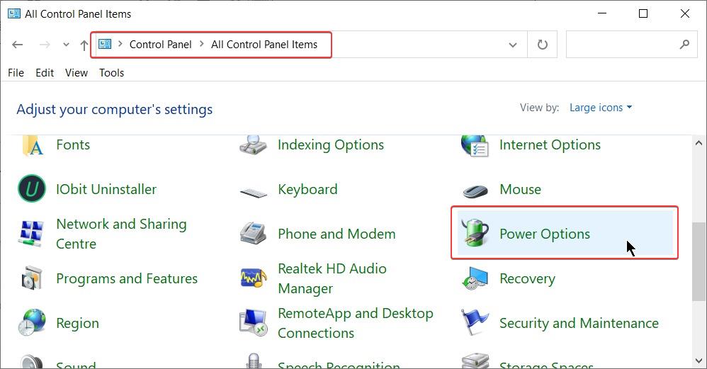
- In Windows OS, open Control Panel.
- Select Control Panel > Power Options.
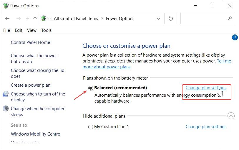
- Click on “Change plan settings” of the active power plans.
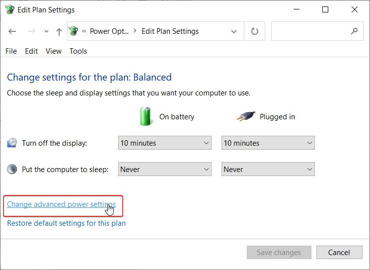
- Click on “Change advanced power settings“
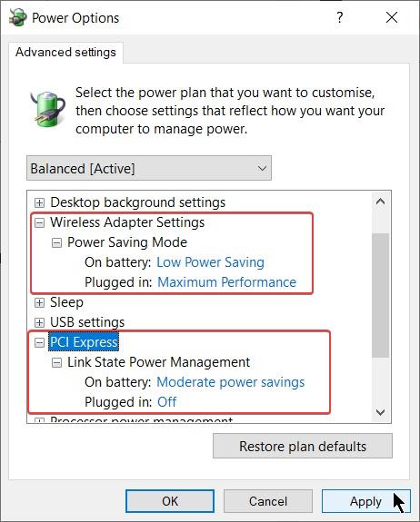
- For maximum WiFi Performance do the following:
- Set Wireless Adapter Settings > Power Saving Mode > Maximum performance.
- If the WiFi adapter is connected to the PCI Express then set PCI Express > Link Power State Management > Off.
- Click on Apply.


- To use power saving mode when the computer is running on the battery do the following:
- Set Wireless Adapter Settings > Power Saving Mode > On Battery > Low Power Saving.
- Set Wireless Adapter Settings > Power Saving Mode > Plugged In > Maximum performance.
- If the WiFi adapter is connected to the PCI Express then set PCI Express > Link Power State Management > On Battery > Moderate Power Saving.
- If the WiFi adapter is connected to the PCI Express then set PCI Express > Link Power State Management > Plugged In > Off.
H. WiFi Router Deployment
- It is recommended to place the WiFi router in the middle of the coverage area, which helps in maximizing the signal strength for each of the receiving Wifi clients(adapters). Placing the WiFi router in the middle is not necessary if the coverage area is small.
- Keep the Wifi Router away from obstructions such as concrete walls, large metallic objects, and electrical equipments.
- Check the WiFi router manual for the correct orientation of the Wifi router antenna.
- If you are facing some network issues in the WiFi network then you must
- Power Off the Router. Wait for 1 minute and then Power On the Wifi Router.
- Reboot the WiFi devices which were connected to this WiFi router.
- Check if it solves the problem.
Related Articles:
I. WiFi Router/Access Point Configuration
To achieve low latency do the following in the 2.4 GHz band 802.11N wireless setting in the WiFi Router if it is available:
- Channel bandwidth: Set the channel bandwidth to 20 MHz for the 802.11N network. Using 20 Mhz channel bandwidth instead of 40 MHz helps in avoiding interference caused by other WiFi networks operating in the same channels.
- In the 2.4 GHz network, set Wireless Mode to N Only.
- Disable WMM ASPD.
- Disable Airtime Fairness.
- Disable Implicit beamforming.
- Set Beacon Interval to 100.
- Disable Roaming Assistant.
- Preamble Type: Short
- IGMP Snooping: Disable it if you don’t use multicast traffic. This type of traffic comes from streaming or smart home devices. Example: Chromecast, WiFi Mirroring.
- Set the Transmitting Power/Transmit Power Control to Highest/100%.
To achieve low latency do the following in the 5 GHz band 802.11AC wireless setting in the WiFi Router setting if it is available:
- Channel bandwidth: Set it to 40 MHz for the 802.11AC network.
- Disable WMM ASPD.
- Disable Airtime Fairness.
- Disable Implicit beamforming.
- Disable Explicit beamforming.
- Disable Universal beamforming.
- Set Beacon Interval to 100.
- IGMP Snooping: Disable it if you don’t use multicast traffic. This type of traffic comes from streaming or smart home devices. Example: Chromecast, WiFi Mirroring.
- Set the Transmitting Power/Transmit Power Control to Highest/100%.
Other WiFi router Settings:
- Don’t enable or use any client filtering features. Example: MAC address filter
- Do not use Network filters. Example: URL Filter, network service filter.
- Do not manually assign IP addresses to any device. Let the DHCP server automatically assign the IP address to all the devices connected to the WiFi router.
- Make sure that no such setting is done in the WiFi Router which restricts the speed of the WiFi clients.
- If the router has a configuration for scheduled reboot then you must Enable it. Rebooting the router once a week is a good practice.
2. WiFi Network issues
A. WiFi Network Connection establishment issues
The WiFi adapter is unable to connect to the WiFi router because of various reasons. For a connection to establish between the WiFi adapter and WiFi router, it is necessary that both have been configured correctly. The connection to the properly configured WiFi network must not take more than three seconds and if it does then there is definitely some issue that needs fixing.
Some of the reasons the WiFi adapter is unable to connect to the Wifi network hosted by the WiFi Router are:
- The WiFi adapter does not support the channel which is being used to host the WiFi network by the WiFi router. This is most evident in the 5 GHz WiFi AC network. For example, one of my 802.11ac adapter support Channels no. 36, 40, 44, and 48 in the 5 GHz bands. It is unable to connect to the WiFi network hosted in Channel no. 52, 56, 60, 64, 149, 153, 157, 161, and 165 in the 5 GHz bands.
- The WiFi adapter does not support the channel width which has been used to host the WiFi network by the WiFi router. This is more evident in the 5 GHz band WiFi network. For example, one of my 802.11ac adapter support only channel bandwidth of 20 MHz and 40 MHz in the 5 GHz band. It is unable to connect to a WiFi network hosted with a channel width of 80 MHz or 160 MHz.
- One scenario is the WiFi router has been configured to host a WiFi network at a particular channel but is unable to properly create a WiFi network on that channel because that channel is not free from interference. In such a situation, the WiFi adapter will connect to the WiFi network with a huge delay or the connection will remain stable. The solution is to change the channel number which has been used to host the WiFi network by the WiFi router.
B. WiFi Network Connection drop
The WiFi adapter is connected to the WiFi router but the connection drops due to various reasons.
- There are multiple WiFi adapters installed on the computer that has been configured to connect to the WiFi router. If the WiFi adapter_1 is connected to the WiFi router and WiFi Adapter_2 is also configured to connect to the same WiFi router then it will automatically connect to the WiFi router. This can cause the WiFi adapter_1 to drop connection to The WiFi router. To fix this issue make sure only one WiFi adapter is configured to automatically connect to the WIFi router. Another fix is to disconnect/disable all of the other WiFi adapters, except the one which you want to use.
- USB WiFi adapter is connected to a port of the USB extension Hub_1. At the same time, other USB devices(USB HDD, USB Keyboard, etc), are connected to the same USB extension hub_1. This causes the distribution of power among the USB WiFi adapter and other USB devices. This may leave the USB WiFi adapter with extremely low power to operate which causes it to drop the connection with the WiFi router.
- USB 2.0 port can deliver a maximum power of 2.5W.
- USB 3.0 / USB 3.1 can deliver maximum power of 4.5 W.
Other online FAQs
C. WiFi network Interference Issues
Your WiFi network experience cochannel interference from other WiFi networks in the area when:
- Other WiFi networks in the area use the same channel to host the WiFi network as your own WiFi network.
- The signal strength of these other wifi networks is relatively strong in the coverage area of your WiFi network.
Devices operating in the 2.4 GHz band :
- Microwave ovens, car alarms, cordless phones, baby monitor, bluetooth devices or wireless video cameras can interfere with wireless channels. Most often, these devices are using the 2.4-GHz frequency.
Interference causes these issues:
- Data throughput decreases.
- Network latency increases.
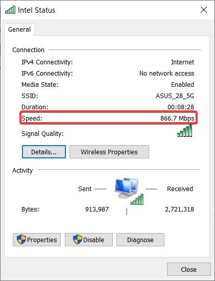
- If the WiFi network is going through speed issues, then you must check the WiFi link Speed between the WiFi Router and WiFi adapter.
- Open Control Panel > Network Connections.
- Right-click on the Wifi Adapter Icon and select Status.

- Check the Link Speed next to “Speed:“. This shows the minimum link speed(PHY speed) for either the download or upload link speed.
- If it link speed is 866.7 Mbps then the actual data throughput speed achievable in the real world to a maximum of 85%(736.7Mbps) of the Link Speed at close range and can be as low as 60%(520Mbps) when the WiFi device is located further away from the WiFi router.
- You can get a data transfer speed of 736.7 Mbps only if your client device is connected to the WiFi router. If more client devices get connected to the WiFi router and each one tries to transfer data at high speed simultaneously then the 736.7 Mbps gets divided among the multiple client devices.
Link Speed = Raw data rate
2. One of the reasons for not reaching maximum throughput speed is interference from other WiFi networks in your area which is using the same wireless channel as your own WiFi network. This is called cochannel interference.
Co-channel Interference is most evident in the 2.4 GHz Wifi network where channels overlap each other.
In a 5Ghz network if another WIFI network is using the same channel as yours own WIFi network, then the interference will cause the maximum transfer speed between the WiFi router and WiFi clients to take a dip.
- https://blogs.arubanetworks.com/industries/an-intro-to-co-channel-interference/
- https://www.ekahau.com/blog/channel-planning-best-practices-for-better-wi-fi/
3. The WiFi signal strength received by the WiFi adapter is a major factor that affects the maximum throughput speed. The signal strength of the receiving WiFi adapter decreases with an increase in the distance between the Router and the WiFi adapter.
4. Plug in the USB Adapter properly in the USB Port. Improper USB port connection can cause slow data transfer speed. Make sure all the USB devices are plugged in properly in the USB port.
Other useful Weblinks:
Information about WiFi channels
Resolving Co-channel interference
- To resolve the co-channel interference you need to know the WiFi channel which is being used by the other WiFi network in your area. To do so you need a WiFi scanner. Some of the good Andriod based Wifi scanners are:
- In the 2.4Ghz 802.11N network, the total number of channels available in most cases is 11. In some cases, the total number of channels available is 13. By default 1,6 and 11 are used by the WiFi router to host the WiFi network. You can do settings in the WiFi router to manually set the channel which will be used to host the WiFi network. You can manually set the channel to number 3 or 9 is free from co-channel interference most of the time.
- In the 5 GHz 802.11AC network, the channels no. available is 34,36,38,40,42,44,46,48,50,52,54,56,58,60,62,64,149,153,157,161. You can do settings in the WiFi router to manually set the channel which will be used to host the WiFi network. First, use the WiFi scanner to check which channels are being used by the other WiFi networks in your area. Then set the WiFi router to use the channel which is free.
- https://en.wikipedia.org/wiki/List_of_WLAN_channels
Related links:
3. Understanding various WiFi adapter terms
- VHT stands for Very High Throughput commonly known as 802.11ac
- HT = High Throughput = 802.11n, 802.11a, Legacy
- AP = Access Point, Wifi Router
- WiFi client device/Endpoints/: A computing device that has a single/multiple WiFi adapter connected to it. It is also referred to as a WiFi adapter or wireless adapter. Endpoints can be computers, mobile devices, printers, and other devices. The WiFi adapter is also called Network Interface Card (NIC).
- Attenuation – a loss in force or intensity – As radio waves travel in media such as coaxial cable attenuation occurs.
- BER – Bit Error Rate – the fraction of bits transmitted that are received incorrectly.
- PER – packet error rate
- Channel Bonding – act of combining more than one channel for additional bandwidth
- dBd – abbreviation for the gain of an antenna system relative to a dipole
- dBi – abbreviation for the gain of an antenna system relative to an isotropic antenna
- dBm – decibels milliwatt — abbreviation for the power ratio in decibels (dB) of the measured power referenced to one milliwatt of transmitted RF power.
- Multipath – refers to a reflected signal that combines with a true signal resulting in a weaker or some cases a stronger signal.
- mW – milliwatt a unit of power equal to one thousandth of a watt (usually converted to dBm)
- Noise Floor – The measure of the signal created from the sum of all the noise sources and unwanted signals appearing at the receiver. This can be adjacent signals, weak signals in the background that don’t go away, electrical noise from electromechanical devices etc.
- Receiver Sensitivity – The minimum received power needed to successfully decode a radio signal with an acceptable BER. This is usually expressed in a negative number depending on the data rate. For example the AP-1140 Access Point requires an RF strength of at least negative -91 dBm at 1 MB and an even higher strength higher RF power -79 dBm to decode 54 MB
- Receiver Noise Figure – The internal noise present in the receiver with no antenna present (thermal noise).
- SNR – Signal to Noise Ratio – The ratio of the transmitted power from the AP to the ambient (noise floor) energy present.
- Radio signal: a high-frequency electromagnetic wave that has long-distance transmission capabilities. Radio signals provide transmission media for 802.11-compliant WLANs. Radio signals described in this document are electromagnetic waves in the 2.4 GHz or 5 GHz frequency band.
Access controller (AC)
A device that controls and manages all of the access points (APs) on a WLAN in the centralized architecture.
Generally in a home WiFi network, the WiFi router acts both as Access Controller and Access Point.
When addional APs are connected to the AC, the AC manages and controls APs in a centralized manner through Control and Provisioning of Wireless Access Points (CAPWAP) tunnels. CAPWAP tunnels provide the following functions:
- Maintain the running status of APs and the AC.
- Help the AC manage APs and deliver configurations to APs.
- Transmit service data to the AC for centralized forwarding.
Access point (AP)
A device that provides 802.11-compliant wireless access for STAs. APs connect wired networks to wireless networks. In a home WiFi network, the WiFi router can act as an Access point if it has such a feature. The Access Point provides only reliable, high-performance wireless connections to WFi client devices and depends on an Access Controller to provide other functions.
An AP can go online in IPv4 or IPv6 mode, and the IPv4 mode takes precedence. The CAPWAP tunnel supports IPv4 and IPv6, but cannot use them concurrently. The AC can only manage APs using either the IPv4 mode or IPv6 mode. The CAPWAP tunnel supports encapsulation of IPv4 and IPv6 packets, but can encapsulate one type of packets at one time, namely, the CAPWAP tunnel can transmit only one type of packets each time.
SSID
Service Set ID (SSID) is a unique identifier that identifies a wireless network. The WiFi router periodically broadcast the SSID of all the wireless networks hosted by it. SSID is sent in Beacon Frame at a time interval called Beacon Interval. Any WiFi adapter can listen to the beacon frame and get the name of the WiFi network hosted by a WiFi router.
Basic service set identifier (BSSID): the link-layer MAC address of an AP.
Extended service set identifier (ESSID): a chosen identifier for one or a group of wireless networks. Multiple APs can use one ESSID to provide roaming service for users; however, their BSSIDs must be unique because the MAC address of each AP is unique.
Beacon Interval
Beacon interval is the time interval at which the WiFi Access Point broadcasts the Beacon frame.
When passive scanning is enabled, an STA listens on the Beacon frames that an AP periodically sends in each channel to obtain AP information,. A Beacon frame contains information including the SSID and supported rate.
multi-path fading
At 2.4 GHz and 5 GHz, RF signals bounce off metal and glass surfaces that are common indoors.
This scattering leads to a situation in which many copies of the signal arrive at the receiver having traveled along many different paths. When these copies combine they may add constructively, giving a good overall signal, or destructively, mostly canceling the overall signal, all depending on the relative
phases of the portions.
small changes in path lengths can alter the situation from good to bad because the wavelengths at 2.4 GHz and 5 GHz (over which the RF signals go through a complete phase) are only 12 cm and 6 cm, respectively. Statistical models tell us that multi-path fading effects are independent for locations separated by as little as half a wavelength. This means that multi-path causes rapid signal changes or
fast fading as the receiver moves, or in the case of a stationary node as the surrounding environment changes. Because multi-path effects depend on the phases of signals, they are strongly frequency selective. This means that some unlucky frequencies in a 20 MHz 802.11 channel may be wiped out
while others are unaffected.
BeamCap
The Beamforming or Transmit Beam Forming (TxBF) technology produces the strong directional radiation pattern based on the strong correlation of the spatial channel and wave interference principle, making the main lobe of the radiation pattern adaptive to point to the wave direction. This technology improves the SNR, system capacity, and coverage range. Beamforming or TxBF is an optional feature in the 802.11n standard.
Beamforming includes explicit Beamforming and implicit Beamforming. Explicit Beamforming requires the receive end to send information about the received signal to an AP. The AP then adjusts the transmit power to the optimal value according to the signal information. This function increases the SNR of the receive end and improves the receiving capability. Implicit Beamforming allows an AP to automatically adjust the transmit power to increase the SNR of the receive end based on channel parameters without requiring the receive end to work with the AP. Currently, mainstream terminals do not support Beamforming.
The key benefits of beamforming are:
1. Reduce dead spots.
2. Deliver stable Wi-Fi connection for voice and HD video.
3. Better Wi-Fi throughput
4. Reduces unnecessary RF interference
802.11n supports implicit and explicit beamforming
802.11ac Supports only explicit Beamforming.
Enable Adaptivity
When enabled this feature will try to change the channel frequency if it detects noise in the currently used WiFi channel. Disable it, if you are relatively closer to the router OR if there are not many WiFi networks around.
Changing the WiFi channel is done by the WiFi router. So the WiFi adapter can only ask the WiFi router to change the channel frequency. If WiFi Router supports such a feature then it may change the channel.
To me, it seems unlikely that this feature will be used.
- Auto: The driver will auto decide to Enable or Disable this feature.
- Disable:
- Enable:
HLDiffForAdaptivity
It’s related to setting parameters for Adaptivity. Keep it to the default settings of Auto.
It could be High-Low Difference for Adaptivity.
L2HForAdaptivity
It’s related to setting parameters for Adaptivity. Keep it to default setting or Auto.
It could be Low to High For Adaptivity.
LDPC
LdpcCap – The Low-Density Parity-Check (LDPC) is a code that enables or disables erroneous correction to reduce the probability of data loss in noisy channels. You should Enable LDPC for Transmission(TX).
LDPC MIMO OFDM
Channel Width or channel bandwidth
This setting allows controlling the width of the channel which will be used for connecting the WiFi adapter to the Wi-Fi Router. The channel width available is 20/40/80/160 MHz. Both the WiFi adapter and WiFi router must support certain channel width otherwise connection between them is not possible at that Channel Width.
Wider channel width allows for Improved maximum throughput. 80 MHz chanel width increase the throughput by 117% compared to 40 MHz Channel width.160 MHz offers speed increases 333 percent compared to 40 MHz channel. With increased bandwidth the data throughput increases but the range of the WiFi network reduces slightly.
The Channel Width available for the 2.4Ghz band WiFi 802.11N network is 20 MHz and 40 MHz. The 40 MHz channel width can be used when there are none or at most one 2.4Ghz WiFi network operating at close range in your area. If there are two or more 2.4Ghz WiFi networks operating at close range in your area then its wiser to use a 20 Mhz channel width because a 40 Mhz channel will experience interference from the other channels operating in your area.
The channel Width available for the 5 GHz band WiFi 802.11AC network are 20/40/80/160 MHz. The Wifi signal at 5 GHz fades so quickly that it is highly unlikely that other Wifi networks hosted in another building/flat using same channel as your network, will cause significant interference to your 5 GHz WiFi network. This makes it easy to use the 160 MHz channel width without experiencing any significant interference from other WiFi networks operating in 5 GHz band. Still, I prefer using 40 or 80 Mhz channel width to host 5 GHz WiFi network because the network link speed remains stable.
The Channel Width available for the 5 GHz band WiFi 802.11N network is 20 MHz,40 MHz, and 80 Mhz.
Modulation
Going from 64QAM to 256QAM also helps, by another 8/6 = 1.33 times faster. Being closer together, the
constellation points are more sensitive to noise, so 256QAM helps most at shorter range where 64QAM
is already reliable.
Guard Interval
A guard interval (GI) is the period of time between each OFDM symbol that is used to minimize intersymbol interference. This allows reflections (from multipath) from the previous data transmission to settle before transmitting a new symbol. When a Symbol is transmitted, the transmitter will wait for a certain period of time (called Guard interval) before transmitting the next symbol. The purpose of a guard interval is to introduce immunity to propagation delays, echoes, and reflections to which digital data is normally very sensitive.
The 802.11n specifies two guard intervals: 400ns (short) and 800ns (long).
Channel/ Frequency band
A channel or frequency band in a WiFi network is a collection of carrier frequencies that are used to transfer data in a WiFi network.
2.4 GHz band Channels: There are 14 channels available in 2.4 GHz band and are spaced 5 MHz from the adjacent channel. The Width of each channel is 20 MHz and they are overlapping with the adjacent channels. The channels in the 2.4 GHz band provide a long range for the WIFi network because it has better capability to penetrate through walls.
The number assigned to the 2.4 GHz band channels are : 1,2,3,4,5,6,7,8,9,10,11,12,13 and 14

5 GHz band Channels: There are a total of 25 channels in the 5 GHz band. The Width of each channel is 20 MHz. Each of the channel, does not overlap with adjacent channels.
The 5 GHz channels have been categorized into four categories:
- UNII-1 :36, 40, 44, 48
- UNII-2a : 52, 56, 60, 64
- UNII-2c Extended : 100, 104, 108, 112, 116, 120, 124, 128, 132, 136, 140, 144
- UNII-3: 149, 153, 157, 161, 165

For example, Channel 1 in 2.4 GHz band is allocated with a lower frequency of 2401 Mhz and ends at an upper frequency of 2423 Mhz which is 22 MHz wide. The control channel(center frequency) is at 2412 Mhz. The usable bandwidth lies between 10 Mhz below the control channel which is 2402 Mhz to 10 Mhz above the control channel which is 2422 MHz. This makes usable bandwidth of 20 MHz between 2402 MHz and 2422 MHz. The left out 2 MHz is used as a guard band, 1 MHz on both sides. So the frequency from 2401 to 2402 MHz and 2422 Mhz to 2423 Mhz is used as a guard band. The signal strength of the Channel 1 radio signal in the guard band is heavily attenuated and does not cause interference to adjacent channels.
For channel 1, the usable 20 Mhz frequency band is from 2402 MHz to 2422 MHz. This frequency band is a band of subcarriers, each having width of 312.5 KHz A total of (20000 KHz/213.5 Khz) 64 subcarriers can exist in the 20 Mhz (20000 KHz) channel. Out of 64 subcarriers, 8 remain unused, 4 subcarriers are used as a pilot and the leftover 52 subcarriers are used for data transmission between the WiFi adapter and WiFi router.
The data rate of 20 Mhz bands is dependent on the number of spatial streams(antenna), the number of usable subcarriers for data transmission, the modulation scheme used, the coding scheme used, the guard interval, and the symbol interval time.
Each subcarrier frequency is a band of 312.5 KHz frequency. This is used to carry digital data in the form called Symbol. In the 802.11N WiFi network, the Symbol time interval has been fixed to 3.2 µs. The guard interval supported is 0.4 and 0.8 µs. If 0.8 µs (800 ns) guard interval is used and each symbol time interval is 3.2 µs then the total time they both consume is 4.0 µs. If each symbol transmits data using 64 QAM then the digital signal transmission capability of each symbol is 6 bits of data per symbol. The highest possible coding scheme that can be used with 64 QAM is 5/6. The most basic spatial stream is one where one antenna is used to transmit data and one antenna is used to receive data on receiving end. The number of data subcarriers in the 20 MHZ frequency band is 52.
Using the formula for PHY throughput = ( No. of data subcarriers) × (Data Bits per symbol when using a certain modulation scheme) × (Coding scheme) × (Spatial stream) / ( Symbol time interval + Guard interval)
Physical data throughput when using 20 MHz channel width in a 802.11N network using 1 spatial stream, 64 QAM modulation scheme with 5/6 Coding scheme and 800ns guard interval = (52 × 6 bits × 5/6 × 1) / ( 3.2 µs + 0.8 µs) = 65 bits / micro second = 65 Mbits / second
More such examples are available here: 802.11 OFDM Data Rates – The Math Behind The Numbers
-
Data subcarriers: used to transmit data.
- Pilot Subcarriers: The pilot subcarriers do not carry modulated data; however, they are used for synchronization purposes between the receiver and transmitter.
- Unused Subcarriers: The remaining unused subcarriers are mainly used as guard carriers or null subcarriers against interference from adjacent channels or sub-channels.

802.11N and 802.11AC PHY data speed
Wireless speed is the product of three factors: channel bandwidth, constellation density, and number of spatial streams. 802.11ac pushes hard on the boundaries on each of these, as shown in Figure 1.
For the mathematically inclined, the physical layer speed of 802.11ac is calculated according to Table 1.
For instance, an 80-MHz transmission sent at 256QAM with three spatial streams and a short guard interval delivers 234 × 3 × 5/6 × 8 bits/3.6 microseconds = 1300 Mbps


Fat channel intolerant
The setting communicates to surrounding networks that the Wi-Fi adapter isn’t tolerant of 40 MHz channels in the 2.4 GHz band. When disabled the adapter doesn’t send this notification.
By Default this setting is Disabled. It is recommended to Enable it.
Wireless Mode
Select which mode to use for connection to a WiFi network.
The meaning of wireless mode settings in the WiFi adapter is somewhat unique to that WiFi adapter and would not be similar to the Wireless mode settings of another WiFi adapter. Choose an option carefully other than the option that has been set as Default.
Options available are-
- Auto : Enables support for all types of WiFi networks supported by the adapter. It is used for optimal performance and compatibility and enables support for all wireless modes. It is recommended to use this option if it is available in the WiFi adapter.
- IEEE 802.11 a : The WiFi adapter will connect only to 802.11a networks only hosted at 5 GHz.
- IEEE 802.11 a/n : The WiFi adapter will connect only to 802.11a/n Wifi access point hosted at 5 GHz.
- IEEE 802.11 a/n/ac : The WiFi adapter will connect only to 802.11a/n/ac Wifi access point hosted at 5 Ghz.
- IEEE 802.11 ac : The WiFi adapter will connect only to 802.11 ac Wifi access point hosted at 5 GHz.
- IEEE 802.11 b : The WiFi adapter will connect only to 802.11b Wifi access point hosted at 2.4 GHz.
- IEEE 802.11 b/g : The WiFi adapter will connect only to 802.11b or 802.11bg Wifi access point hosted at 2.4 GHz.
- IEEE 802.11 b/g/n : The WiFi adapter will connect only to 802.11g/g/n Wifi access point hosted at 2.4 GHz.
- Dual Band 802.11 a/g : The WiFi adapter will connect only to 802.11a/g Wifi access point hosted at 5 Ghz or 2.4 GHz band .
- Dual Band 802.11 a/b/g : The WiFi adapter will connect only to 802.11a/b/g networks hosted at 5 Ghz or 2.4 GHz band .
802.11a/b/g Wireless Mode or Wireless Mode
Allows you to select whether the WiFi adapter operates in the 802.11b, 802.11g, and 802.11a bands.
- 5 Ghz 802.11a : The wireless adapter will be able to connect to 802.11a networks only, hosted in the 5 GHz band. Selecting this option disables 2.4 GHz radio in the WiFi adapter.
- 2.4 Ghz 802.11b only: The wireless adapter will be able to connect to 802.11b networks only, hosted in the 2.4 GHz band. Selecting this option disables 5 GHz radio in the WiFi adapter.
- 2.4 Ghz 802.11g only: The wireless adapter will be able to connect to 802.11g networks only, hosted in the 2.4 GHz band. Selecting this option disables 5 GHz radio in the WiFi adapter.
- 2.4 Ghz 802.11b and 802.11g: The wireless adapter will be able to connect to 802.11b and 802.11g networks only. in the 2.4 GHz band. Selecting this option disables 5 GHz radio in the WiFi adapter.
- Dual band 802.11a and 802.11g: The wireless adapter will be able to connect to 802.11a wireless networks hosted in the 5 GHz band and 802.11g networks only in the 2.4 GHz band.
- Dual Band 802.11a, 802.11b, and 802.11g (default): The wireless adapter will be able to connect to the 802.11a wireless networks hosted in the 5 GHz band, 802.11b networks in the 2.4 GHz band and 802.11g networks in the 2.4 GHz band.
SISO
Conventional communication systems that only have a single transmit antenna and a single receive antenna are called Single Input Single Output (SISO) communication systems.
Spatial Diversity/Antenna Diversity ( Use of mutiple antennas)
Space diversity is also called antenna diversity or spatial diversity.
A wireless technique that uses multiple antennas to receive or transmit signals along different propagation paths to compensate for multi-path interference and multipath fading. Spatial diversity is one of a number of methods used in radio communications to improve the robustness of transmitted signals and minimize fading and interference.

WiFi antenna diversity utilizes multiple 2.4 GHz or 5 GHz antennas, switching between them to source the best radio frequency signal for data transmission. On a typical router, WiFi antennas are located in separate locations so that each receives a different version of the client signal.
A technique that can be used to recover radio communication in environments with difficult reception. Antenna diversity can greatly improve performance under multi-path fading conditions.
While antenna diversity can achieve significant range improvements in wireless communication systems, it is often not implemented due to the added complexity, computation cost, and current consumption that is required to implement the requisite algorithm on the system.
To mitigate the problem of frequency-selective fading due to multi-path propagation, a technique known as antenna diversity can be used. Antenna diversity uses a pair of antennas that are physically separated in location and possibly differ in mounting orientation (i.e., polarization) relative to the radio. Each time the device enters receive (RX) mode, the receive signal strength from each antenna is evaluated. This process is continuously repeated until a valid signal is detected on one of the antennas. The antenna with the strongest received signal strength is then used to receive the remainder of the packet. The same antenna may also be used for transmitting the corresponding transmit (TX) packet. However, it should be noted that there is no guarantee that the fading characteristics of the return TX path match the fading characteristics of the RX path.
Products that implement antenna diversity quite often also have their antennas mounted at 90 degrees from one another for the purpose of countering the effects of polarization/directionality on the radio link.
There are two basic classes of multiple antenna techniques:
- Spatial diversity: Combating fading effects by creating spatial diversity through the
use of baseband space-time coding techniques. - Spatial Multiplexing: Using spatial multiplexing techniques to exploit multipath in
order to achieve higher data rates than are possible with conventional systems having
the same bandwidth
- Spatial diversity techniques increase reliability and range by sending or receiving redundant streams of information in parallel along the different spatial paths between transmit and receive antennas. The use of extra paths improves reliability because it is unlikely that all of the paths will be degraded at the same time. Improved range, and some performance increases too, come from the use of multiple antennas to gather a larger amount of signal at the receiver.
- Receive Diversity (SIMO): It has a single transmit and multiple receive antennas. For instance, one transmit antenna at a node is sent to two receiving antennas. This is known as a 1×2 system.
- The simplest method is to use the antenna with the strongest signal (hence the largest SNR) to receive the packet and ignore the others. This method is called SEL, for selection combining. This is essentially what is done by 802.11a/g.
- The second method is to optimally combine signals from separate receiving antennas so that the resultant signal exhibits a reduced amplitude variation. To do this, the receiver needs a dedicated RF chain for each antenna to process the signals. This increases the hardware complexity and power consumption but yields better performance. The result is maximal-ratio combining or MRC. MRC allows the receiver to process both signals independently, and then combine them, weighted by the strength of each signal, to extract a more accurate replica of the transmitted data-stream than it could from a single antenna. In simple terms, when one antenna is in a ‘null’ and has a bad signal, the other is likely to have a good signal. The receiver will only suffer when all antennas have bad signals simultaneously. As the number of antennas increases, the probability of bad conditions for all of them simultaneously becomes progressively smaller. For example, a mobile phone with one antenna transmits data to the Wifi router with two or more antennas.
- Receive Diversity (SIMO): It has a single transmit and multiple receive antennas. For instance, one transmit antenna at a node is sent to two receiving antennas. This is known as a 1×2 system.
-
- Transmit Diversity (MISO): This arrangement has multiple transmit antennas and a single receive antenna. The transmitter must know the channel beforehand in order to select between antennas or to precode the signals. This requires feedback from the receiver,
i.e. RSSI or packet delivery statistics to inform selection and channel gains to inform precoding.- The transmitter simply selects the single best antenna from the multiple antennas available which will be used to transmit a the data.
- The transmitter precodes the signals by delaying them to change the phase such that they combine constructively at the receiver’s antenna, and weighting them such
that transmit power is allocated to each spatial path by its SNR. Its a type of beamforming. For example, a WiFi router with two or more antennas transmits data to a mobile phone with one antenna. - STBC: The advanced class of transmit diversity techniques called space-time codes that do not need feedback to work, but instead require a change in the receiver’s processing. For example, when two Transmit antennae and one receive antennae are used for STBC, the transmitter sends the same user data to both transmit antennas, but at different times, for improving the probability of successfully recovering the desired data. This technique a send the data signal by encoding in both multiple antennas (space) and time enabling a specialized receiver to aggregate the spatial paths. Space-time codes are simpler to use than precoding but have worse performance for more than two transmit antennas.
- Transmit Diversity (MISO): This arrangement has multiple transmit antennas and a single receive antenna. The transmitter must know the channel beforehand in order to select between antennas or to precode the signals. This requires feedback from the receiver,
- Spatial Multiplexing: Also called MIMO which uses Spatial multiplexing techniques to increase performance by sending independent streams of information in parallel along the different spatial paths between transmit and receive antennas. Spatial multiplexing takes advantage of the extra degrees of freedom provided by the independent spatial paths to send independent streams of information at the same time over the same frequencies.
- The streams will become combined as they pass across the channel, and the task at the receiver is to separate and decode them. consider the case where each node has N antennas and in an ideal (best-case) channel with independent spatial paths between the pairs of transmit and receive antennas. The N^2 paths provide an N^2 increase in SNR using diversity optimally. There are N spatial degrees of freedom in the system, since the signal from each transmit antenna can change the received signals in a different manner.1 By using the antennas to divide the transmit power over these degrees of freedom, the transmitter can divide its power to send N spatial streams of data, each getting an SNR of ρ when combined at the receiver.
- direct-mapped MIMO : The simplest way to get spatial multiplexing benefits is to
transmit spatial streams by dividing transmit power equally and sending each directly out one transmit antenna. For instance, in a 2×2 system, there are two transmitters (Tx) and two receivers (Rx) antennas. At the transmitting end, each transmitter antenna will transmit a separate data stream. Both the antenna in the receiving end will receive a mix of two signal streams. - Precoded MIMO: Better can be done by precoding the data stream and transmitting the multiple separate data stream using multiple Transmit antennae and also using multiple antennae at the receiving end. In addition, we can benefit from knowledge and work at the transmitter. This time a precoding technique is used at the transmitter, which makes sure that the streams do not interfere and are easy to decouple at the receiving end. Each subcarrier data stream signal can be independently and easily decoded. The downside of this strategy is that, as with transmit diversity, the transmitter must know the channel gains and track them as the channel changes.
- direct-mapped MIMO : The simplest way to get spatial multiplexing benefits is to
- The streams will become combined as they pass across the channel, and the task at the receiver is to separate and decode them. consider the case where each node has N antennas and in an ideal (best-case) channel with independent spatial paths between the pairs of transmit and receive antennas. The N^2 paths provide an N^2 increase in SNR using diversity optimally. There are N spatial degrees of freedom in the system, since the signal from each transmit antenna can change the received signals in a different manner.1 By using the antennas to divide the transmit power over these degrees of freedom, the transmitter can divide its power to send N spatial streams of data, each getting an SNR of ρ when combined at the receiver.
If noise or interference affects the signals unevenly, MRC or STBC techniques can restore it to a
clear-channel line-of-sight condition, but in the absence of multipath, only one stream can be supported, and the upper bound on performance is a clear-channel single-stream.
MIMO SDM
MIMO (Multiple Input, Multiple Output) is used for Spatial division multiplexing(SDM).
Multiple Input multiple output (MIMO) is an antenna system that consists of the use of multiple transmit antennas and multiple receive antennas to transmit multiple streams on the same frequency band. The MIMO technology allows spaces to become the resources used to improve performance and increases the coverage range of the wireless system.
Multiple antennas placed at the transmitter and/or receiver in wireless communication systems can be used to substantially improve system performance by leveraging the “spatial” characteristics of the wireless channel. These systems, now widely termed as Multiple Input Multiple Output (MIMO),
require two or more antennas placed at the transmitter and at the receiver. In MIMO terminology, the “Input” and “Output” are referenced to the wireless channel. In these systems, performance gains are achieved as multiple transmitters simultaneously input their signal into the wireless channel and
then combinations of these signals simultaneously output from the wireless channel into the multiple receivers.
The MIMO system generates multiple spatial flows with each antenna generating a maximum of one spatial flow. The MIMO technology allows multiple antennas to send and receive multiple spatial flows (multiple copies of signals) simultaneously and to differentiate the signals sent to or received from different spaces.
Under normal, line of sight conditions, the receiving antennas all ‘hear’ the same signal from the transmitter. If the transmitter attempts to send two different signals using transmit antennas A and B, those signals will arrive simultaneously at the receiver, and will effectively interfere with each other.
For MIMO SDM to work requires that Radio signal received at the receiver has sufficient RF distortion and the radio signal has used multipath to reach the receiver antenna. Generally RF distortion and multipath causes problems in wireless transmission. But with MIMO SDM these are actually helpful. If there is sufficient RF distortion and especially multipath in the path, receiving antennas will see
different signals from each transmit antenna.
An 802.11n device supports up to 4×4 MIMO, a maximum of four spatial flows, with a rate of up to 600 Mbit/s. It supports a maximum of four streams and provides a maximum throughput of up to 600 Mbit/s.
802.11ac supports a maximum of eight streams ( 8×8 MIMO) and provides a maximum throughput of approx 7 Gbit/s for a single user.
The MIMO technology provides the system with spatial multiplexing gain and spatial diversity gain.
In spatial multiplexing, multiple antennas are used on the receiving end and transmit end, and multipath components in spatial communication are used, allowing signals to be transmitted over multiple data channels (MIMO sub-channels) in the same frequency band. This technology makes the channel capacity linearly increase with the growing number of antennas. This increase in channel capacity does not require additional bandwidth and does not consume additional transmit power. Therefore, spatial multiplexing is an efficient means to improve channel capacity and system capacity.
In spatial multiplexing, serial-to-parallel conversion is performed on the transmitted signal to produce several parallel signals flows, which are then transmitted using their respective antennas in the same frequency band simultaneously. Due to the use of multipath propagation, each transmits antenna produces a unique spatial signal for the receiving end. After the receiving end receives the mixed signals of data, it differentiates these parallel data flows based on the fading between different spatial channels. Spatial multiplexing requires the spacing between transmit and receive antennas to be greater than the distance, ensuring that each sub-channel of the receiving end is an independently fading channel.
Benefits:-
- Improved maximum throughput
- Increased number of users
- Enhanced link reliability
Line of Sight comm:
STBC MISO
StbcCap – Space Time Block Coding (STBC) is an 802.11n technique intended to improve the reliability of data transmissions. STBC is achieved by using MISO(Multiple Input and Single Output) antenna systems. Multiple antennae are used to transmit data from the transmitter and only one antenna is used to receive data at the receiver. STBC using two transmit antenna and one receive antenna will be called 2X1.
STBC is another diversity technique for improving SNR, but is applied when the number of transmitting antenna chains exceeds the number of receive antennas.
Space time block coding (STBC) sends the same user data to both transmit antennas, but at different times, for improving the probability of successfully recovering the desired data. STBC produces multiple receive versions of data at the receiver. Among these data copies, optimal copies are combined to provide the most reliable data. This redundancy increases the chance of using one or more copies of received data to correctly decode the received data. STBC combines all the copies of received signals to produce useful data.
Space-Time Block Coding (STBC) can be used when the number of radio chains exceeds the number of spatial streams. In effect, STBC transmits the same data stream twice across two spatial streams so that a receiver that misses a data block from one spatial stream has a second shot at decoding the data on the second spatial stream. In effect, STBC takes the gains from MISO and uses them nearly exclusively for an increased range. A single encoding stream must take two radio chains for transmission, which means that a 2×2 MIMO device transmitting with STBC is effectively operating as a single-stream device. 802.11 interfaces include a step-down algorithm that selects slower and more reliable transmission rates. STBC can be used when the data channel is too poor to support one full stream per radio. In such environments, STBC is worth the 50% penalty on transmitted speed. When an STBC-enabled AP is serving mainly single-stream devices at long ranges, STBC is definitely worth considering.
The form of space-time coding used in 802.11n is the Alamouti code. This spreads one spatial stream over two space-time streams, taking a pair of data-stream bits, and performing operations on them in consecutive time intervals.
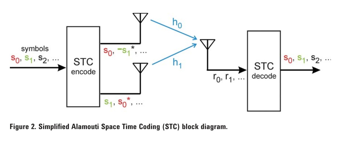
A simplified block diagram using Alamouti STC is shown in Figure 2. In this system, two different symbols are simultaneously transmitted from the two antennas during any symbol period. During the first time period, the first symbol in the sequence, s0, is transmitted from the upper antenna #1 while the second symbol, s1, is simultaneously transmitted from the lower antenna #2. During the next symbol time the signal -s1* is transmitted from the upper antenna and the signal s0* is transmitted from lower antenna. Note that ( )* is the complex conjugate operation.
At the receiver, a single antenna receives a combination of the two transmitted signals after transmission
through the multipath environment. The channel coefficient, h0, represents the magnitude and phase of the transmission path between transmit antenna #1 and the receive antenna. The channel coefficient, h1, represents the path between transmit antenna #2 and the receive antenna. In order to recover the actual transmitted symbols, s0 and s1, the receiver requires knowledge of the channel coefficients, h0 and h1.
MIMO and beamforming
Here MIMO is used for beamforming. Beamforing is regarded as Precoding.
Beamforming is a technique that focuses the AP transmit energy of the MIMO spatial stream towards the
targeted station (STA) or client device. Using channel estimation carefully to introduce a small difference in the phase and amplitude in the transmission (precoding) allows the AP to focus the transmitted signal in the direction of the receiving STA.
The beamforming requirements are completely opposite to good MIMO requirements. In order to increase diversity in MIMO, we want signals from different antennas to have orthogonal polarity.
The 802.11ac specification defines a single closed-loop method for transmit beamforming. In this method, the AP transmits a special sounding signal to all STAs, which then estimates the channel and reports their channel feedback back to the AP. This feedback from STAs is standardized so consumers can be sure any standardsbased beamforming devices (APs and STAs) interoperates with all other 802.11ac compliant products.
You can optimize your antenna array for either beamforming performance or MIMO – but not both.
MIMO power save mode
MIMO power save mode, also known as spatial multiplexing power save (SMPS) mode, allows the client to save power by keeping one antenna in a receive idle state.
- Auto SMPS: The client decides automatically what SMPS mode to apply depending on different conditions. You should use this option when you want to save some power and connect to multiple WiFi router.
- Dynamic SMPS: The client keeps only one antenna active. The access point (AP) must send request to send (RTS) packet to trigger the client to wake the sleeping radios/antenna before sending MIMO packets.
- Static SMPS: The client keeps only one antenna active and the AP cannot send MIMO packets to the client.
- No SMPS: The client always keeps all antennas active and the AP can send MIMO packets to the client. If you do not want to save power and
Maximal ratio combining (MRC)
The maximal ratio combining (MRC) technology improves the signal quality of the receiving end.
In MRC, the same signal from the transmit end is received by the receive end through multiple paths (multiple antennas) because the receive end receives this signal using multiple antennas. Generally, among multiple paths, there is one path providing better signal quality than the other paths. The receive end uses a certain algorithm to allocate different weights to receiving paths. For example, the receive end allocates the highest weight to the receiving path providing the best signal quality, which improves the signal quality of the receive end. When none of multiple receiving paths can provide better signal quality, the MRC technology can ensure better receive signals.
USB SF Mode
It is related to the USB port of the computer to which the USB WiFi adapter is connected. It is USB Switch Fast Mode.
- Disable: USB Switch fast Mode is disabled
- Enable: USB Switch Mode will change the mode quickly.
USB Switch Mode
It is related to the USB port of the computer to which the USB WiFi adapter is connected.
- Auto: It means a USB WiFi adapter will auto-select a mode( USB1, USB 2 or USB 3) for connection to the computer USB port.
- USB Mode 1 – It means a USB WiFi adapter will try to connect to the computer USB port with USB 1.1 spec.
- USB Mode 2 – It means a USB WiFi adapter will try to connect to the computer with USB 2.0 spec.
- USB Mode 3 – It means a USB WiFi adapter will try to connect to the computer with USB 2.0 spec.
Roaming Aggressiveness/Roaming Sensitivity
This setting lets you define how aggressively your wireless client roams to improve the connection to an access point.
This is useful when the WiFi adapter is working in multiple WiFi Router environments. The WiFi adapter will check the signal strength from the WiFi router to which it is connected. If the signal strength drops below a certain point then it will scan for other WiFi routers with better signal strength. If a WifI router with better signal strength is found then the WiFi adapter will disconnect from the current WiFi router and connect to another WiFi router.
- Default: Balanced setting between not roaming and performance.
- Lowest: Your wireless client will not roam. Only significant link quality degradation causes it to roam to another access point.
- Highest: Your wireless client continuously tracks the link quality. If any degradation occurs, it tries to find and roam to a better access point.
U-APSD support (WMM Power Save)
U-APSD is an acronym for Unscheduled Automatic Power Save Delivery, which is a feature of Wi-Fi devices (for battery-powered equipment) that allows them to save power. U-APSD is also known as WMM-Power Save or WMM-PS. U-APSD is a Wi-Fi capability that provides more power consumption savings on the client, in low periodic latency-sensitive traffic modes, like a VOIP.
uAPSD enables a STA(WiFi-enabled device) to retrieve unicast Quality of Service (QoS) traffic buffered in the AP by sending trigger frames. During association/reassociation, a STA negotiates uAPSD capabilities with the access point. For a non-U-APSD enabled access point, a STA uses legacy mechanisms as a means to retrieve the legacy power-save buffered frames.
The uAPSD-enabled AP advertises its capability by setting the uAPSD bit of the QoS Info field in either the WMM Information Element or the WMM Parameter Element. This capability is advertised in Beacons, Probe Responses and reassociation Responses.
Unscheduled automatic power save delivery (U-APSD) is a QoS facility that is defined in IEEE 802.11e that
extends the battery life of mobile clients. In addition to extending the battery life, this feature reduces the
latency of traffic flow that is delivered over the wireless media. Because U-APSD does not require the client to poll each individual packet that is buffered at the access point, it allows the delivery of multiple downlink packets by sending a single uplink trigger packet.
When this feature is used, the data packet arriving at the WiFi router for a Wifi client is buffered in the WiFi router because the WiFi client is in sleep mode. The WiFi router indicates data availability using the AID (Association IDentifier) in the TIM (Traffic Indication Map) frame which it sends at predicted intervals. WiFi client device listens to TIM frame at a specified interval. When the WiFi device knows that data packets have been buffered by the WiFi Router, it wakes up and sends a QoS trigger frame to the WiFi router. Then Wifi router sends the buffered data packets to the Wifi client device. When there are no more data packets left to be sent to the WiFi client, the WiFi client enters Sleep mode. During the Sleep mode, the WiFi adapter saves power. At the same time, it adds latency to the network data transmission.
AP mode Force BW20
Enabling this will force channel bandwidth to 20 MHz when the WiFi adapter is used for creating a WiFi hotspot (WiFi adapter is used as Access Point).
Selective suspend
Enabling this allows the computer to suspend power to the USB port in which the WiFi adapter has been plugged in.
Multimedia/Gaming Environment
Enabling this will enable QoS which will give preference to media streaming and gaming data in the network. Enabling this ensures that media streaming and gaming data get high priority in the WiFi network. This is useful for uninterrupted and low latency transfer of data by gaming applications.
Channel Mode
It applies to dual-band WiFi adapters.
- Auto/(2.4G + 5G) : The Wifi adapter will support connection to both 2.4 GHz and 5 GHz band.
- 2.4G only : The Wifi adapter will support a connection in 2.4 GHz band only.
- 5G only : The Wifi adapter will support a connection in 5 GHz band only
802.11n Channel Width for band 2.4 GHz
Allows the user to set channel width at 2.4 GHz band.
- 20 MHz only : Only 20 MHz channel width will be used while connecting to the WiFi network at 2.4 GHz band.
- Auto : Wifi router decides channel width will be used while connecting to the WIFi network at 2.4 GHz band.
802.11n Channel Width for band 5 GHz
Allows the user to set channel width at 5 GHz band.
- 20 MHz only : Only 20 MHz channel width will be used while connecting to the WiFi network at 5 GHz band.
- Auto : Wifi router decides channel width will be used while connecting to the WIFi network at 5 GHz band.
802.11n Mode
- Enable : Enables connection to 802.11n network
- Disable : Disables connection to 802.11n network
Ad Hoc QoS Mode
This setting is used when the WiFi adapter is connected to Adhoc wifi network. Quality of Service (QoS) control in ad hoc networks prioritizes traffic from the access point over a wireless network based on traffic classification. WMM (Wi-Fi Multimedia) is the QoS certification of the Wi-Fi Alliance (WFA). When WMM is enabled, the WiFi adapter uses WMM to support priority tagging and queuing capabilities for Wi-Fi networks.
- Enabled : The WiFi ad-hoc network will prioritize video and voice traffic
- Disabled : The WiFi ad-hoc network will give equal priority to all types of data traffic.
Wi-Fi Multimedia (WMM)
This feature provides basic Quality of service (QoS) features to IEEE 802.11 networks. WMM prioritizes traffic according to four Access Categories (AC):
- Voice (AC_VO) : Allocates bandwidth for voice traffic generated from incoming and outgoing voice communication. This traffic is given the highest priority because it requires low latency. At the same time, there is no guarantee that every data packet will be transferred at low latency.
- Video (AC_VI) traffic generated from video streaming
- Best effort (AC_BE) such as traffic from legacy devices or traffic from applications, web browsers, or from the devices that do not support QoS.
- Background (AC_BK) traffic such as file downloads or print jobs
It is suitable for well-defined applications that require QoS, such as Voice over IP (VoIP) on Wi-Fi phones (VoWLAN).
QoS Support
QoS feature helps in prioritizing voice, audio, and video data transmission. It supports IEEE 802.11e QoS Enhancement (WMM).
- Support QoS: The WiFi adapter will use the Qos feature.
Ad Hoc Power Management
Set the power-saving features for Device to Device (ad hoc) networks.
- Disable: Select when connecting to ad hoc networks that contain WiFi devices that do not support ad hoc power management.
- Maximum Power Savings: Select to optimize battery life.
- Noisy Environment: Select to optimize performance or connect with multiple clients.
VHT 2.4G
This feature enables support for a Very High Throughput(VHT) connection in the Wifi N network hosted in 2.4 GHz band. It is achieved by supporting MCS index 8 and MCS index 9. This increases the link speed between the WiFi adapter and the WiFi router.
MCS index = Modulation and Coding Scheme Index
MCS index 8 refers to the use of 256 QAM modulation and 3/4 Coding. It is usable in both 20 MHz and 40 MHz channel widths.
MCS index 9 refers to the use of 256 QAM modulation and 5/6 Coding. It is used in 40 MHz channel width only.
The WiFi router must also support the MCS index 8 and 9. Otherwise, this feature of the WiFi adapter will not be used.
- Disable: The Wifi adapter will not support MCS index 8 and 9 while connecting to the WiFi N network hosted in 2.4 GHz band. Keep it disabled if the WiFi-enabled device is mobile or is located in a room that is separate from the room in which the WiFi router has been kept.
- Enable: The Wifi adapter will support MCS index 8 and 9 while connecting to the WiFi N network hosted in 2.4 Ghz band. Keep it Enabled only when the WiFi device will remain located in the same room in which the WiFi router is kept and the WiFi device remains stationary in that room for most of the time.
VHT 2.4G IOT
IOT = Internet of Things
VHT = Very High Throughput
Supporting VHT in the 2.4Ghz band will help in increasing the throughput. To achieve VHT in 2.4 GHz band 256 QAM is used. In an indoor environment, the VHT connection is stable when all the WiFi devices are located in the same room in which the WiFi router has been kept.
- Disable: The Wifi adapter will not support VHT while connecting to the 802.11N WiFi IoT network hosted in 2.4 GHz band.
- Enable: The Wifi adapter will support VHT while connecting to the 802.11N WiFi IoT network hosted in 2.4 GHz band.
Channel Width for 2.4GHz
This setting is used to set the Channel Width for connection to a WiFi network hosted in 2.4 GHz band.
- Auto: The WiFi adapter will support both 20 MHz and 40 MHz channel width for connection to the WiFi network.
- 20 MHz: The WiFi adapter will only support 20 MHz channel width for connection to the WiFi network. This may cause the WiFi adapter unable to connect to the 802.11N WiFi network hosted with a 40 MHz channel width or may cause stability & performance issues even if it gets connected.
Roaming aggressiveness
This setting alters the signal strength threshold at which the WiFi adapter starts scanning for another candidate AP. The default value is Medium. Depending on the environment, one option may work better than the other. You may try other values to see which works best for your environment. However, it is recommended to revert back to the default (Medium) if no improvement is observed with other values.
- Lowest: The WiFi adapter will trigger scan a for another candidate AP when the signal strength with the current AP is very low.
- Medium-Low
- Medium (default): Recommended value.
- Medium-High
- Highest: The WiFi adapter will trigger scan a for another candidate AP when the signal strength with the current AP is still good.
Wake-on-Wireless LAN
In short, it is named WoWLAN.
Wake on Wireless LAN is a feature to allow the computer system to go into a low-power state (e.g. ACPI S3 suspend(sleep), shutdown state(S5)) while the wireless adapter remains active(D3 state) and does specific things. Non WoWAN frames which are received by the wireless adapter are ignored (dropped), but certain specific WoLAN frames received should be ACKed by the wireless adapter without waking up the computer system from its sleep state.
Waking the computer Up from a different power state:
- Sleep state: This state is most likely to support the WoWLAN feature because the base driver for the wireless adapter supports this feature.
- Shutdown state : Supporting WoWLAN in this state would require full driver suite from the manufacturer of the wireless adapter.
OS support for WoWLAN
- Windows 10: WoWLAN is supported from sleep (S3), hibernate (S4) state and Shutdown(S5) state. WoWLAN is not supported for hybrid shutdown (also known as Fast Startup) (S4).
- Windows 7: WoL is supported from sleep (S3). WoWLAN from S5 isn’t officially supported in Windows 7. However, some network adapters and BIOS/UEFI can be configured to support waking up the system which is in the Studown(S5) state.
Wireless adapter requirements for WoWLAN feature:
- The WiFi adapter driver must support the WoWLAN feature.
- The WiFi adapter must be in Infrastructure Station mode
WiFi Router requirements:
- WiFi router must be using either WPA2-Enterprise (WPA2) or WPA2-Personal (WPA2-PSK) authentication.
To enable the WoWLAN feature do the following:
- The WiFi adapter driver must support this feature.
- Enable the (Wake on LAN) and (Wake on WLAN) features in the BIOS/UEFI setting if it is available.
When certain data packets are received then the WiFi adapter will Wake Up the computer system from sleep mode:
- When packets called the Magic Packets are received by the WiFi adapter.
- When packets with certain specific patterns are received by the WiFi adapter.
- Wake device on media connect
Additionally, the WiFi adapter will Wake Up the computer system from sleep mode when the following events occur :
-
GTK Handshake Error: In this case, the WiFi adapter encounters an error in a two-way handshake.
-
802.1x EAP-Request/Identity Packet Received
In this case, the operating system attempts WPA2-Enterprise authentication by sending an 802.1x EAP-Request/Identity WOL pattern. -
Four-way Handshake Request Received
In this case, the WiFi adpater receives a request from the associated Acess Point to perform a four-way handshake authentication. When the host computer is awake, the operating system performs the four-way pairwise transient key (PTK) handshake procedure.
Some services can be offloaded to the WiFi adapter which it will do without waking up the computer system from sleep mode.
- IPv4 ARP(ARP offloading for WoWLAN)
- IPv6 Neighbor Solicitation (NS) (NS offload for WoWLAN)
- IEEE 802.11 robust secure network (RSN) 4-way and 2-way handshake. (GTK Rekeying for WoWLAN)
Wake-on-LAN uses UDP port 9 by default. Wake-on-LAN-enabled computers essentially wait for a “magic packet” to arrive that includes the network card’s MAC address in it. These magic packets are sent out by professional software made for any platform, but can also be sent by routers and internet-based websites.
ARP offloading for WoWLAN
ARP offload is the network adapter’s ability to handle IPv4 Address Resolution Protocol (ARP) without waking up the computer system from Sleep Mode. To enable the feature, both the network hardware and the driver must support ARP offload.
This feature is used when the WoWLAN feature has been enabled and the computer system gets in sleep mode.
- Enabled: The WiFi adapter will respond to ARP requests while the system is in sleep mode. This will let the WiFi router know the presence of this WiFi adapter in the network.
- Disabled: The WiFi adapter will respond to ARP requests after waking up the computer from sleep mode.
GTK Rekeying for WoWLAN
Group Temporal Key (GTK) Rekey refers to the process of changing the session key used to encrypt and decrypt network traffic. It will be used only when Wake on Wireless LAN (WoWLAN) feature has been enabled in the computer system and in the wireless adapter settings. When it is enabled the WiFi adapter offloads the group temporal key (GTK) rekeying for wake-on-wireless-LAN (WOL) when the computer enters a sleep state.
WiFi router requirement:
- WiFi router must be using either WPA2-Enterprise (WPA2) or WPA2-Personal (WPA2-PSK) authentication.
Group Temporal Key (GTK) is a change initiated by the WiFi router at a certain specific interval of time.
- Enabled: When this option is selected the WiFi adapter will do the rekeying procedure without waking up the computer system from sleep mode. If the WiFi adapter is not able to perform GTK rekeying due to some reason then it will Wake Up the system and complete the rekeying procedure.
- Disabled: When this option is selected the WiFi adapter will do the rekeying procedure after waking up the computer system from sleep mode.
The overlying driver will request the network adapter to enable the IEEE 802.11i Robust Security Network (RSN) protocol offload capability. As soon as this protocol offload has been configured by a set request of OID_PM_ADD_PROTOCOL_OFFLOAD, the driver should enable the network adapter to respond to RSN re-key requests packets while it is in a low power state.
NS offload for WoWLAN
A value that describes whether the device should be enabled to offload neighbor solicitation (NS) when the computer system enters a sleep state and the WiFi adapter has been configured to use the WoWLAN feature.
NS offload is the network adapter’s ability to respond to a Neighbor Discovery Neighbor Solicitation request with a Neighbor Advertisement without waking the computer. Both the hardware and the driver must support NS offload to enable this feature.
If the request is successful, the network adapter must generate and transmit the necessary response packets for the offloaded protocol when the network adapter is in a low power state.
A protocol driver can offload a protocol after it successfully binds to an underlying network adapter and as soon as it has the necessary data (such as the IP address of the interface) to offload the protocol. The protocol driver can also offload a protocol in response to some other power management event notifications, such as the rejection of a previously added WOL pattern or an offloaded protocol.
- Enabled:
- Disabled:
Sleep on WoWLAN disconnect
This feature is used when the WoWLAN feature has been enabled and the computer system gets in sleep mode.
- Enabled: If a connection to the WiFi Router gets disconnected the WiFi adapter will put itself into a low-power state (sleep state,D3 state) and return to a full-power state (wake state, D0 state) when the WiFi adapter is connected again.
- Disabled: When the connection to the WiFi Router gets disconnected, the WiFi adapter will not put itself into a low-power state (sleep state).
D3 on disconnect feature under these conditions:
- The network adapter hardware must be able to generate a wake event on media connect.
- The network adapter must be an PCI adapter.
- In Windows OS, Sleep on disconnect is only available while the computer is fully powered in the working state (S0). The WiFi adapter must support Sleep state (D3) when the computer system is in Full Power State (S0). You won’t be able use this feature when computer system enters Sleep Mode (S3).
- The WiFi adapter must support
DeviceSleepOnDisconnect
If this feature fails to work properly then the WiFi adapter will Wake up the computer system from sleep mode.
Wake on magic packet
Supports Wake-On-WLAN via Magic Packet and Wake-up frame. The magic packet is a broadcast frame containing anywhere within its payload 6 bytes of all 255 (FF FF FF FF FF FF in hexadecimal), followed by sixteen repetitions of the 48-bit MAC address of the target computer, for a total of 102 bytes.
- Enabled: The setting wakes the computer from a sleep state when it receives a Magic Packet from a sending computer. The Magic Packet contains the MAC address of the intended destination computer.
- Disabled: Turns off Wake on Magic Packet feature.
Wake on pattern match
Supports Wake-On-WLAN via pattern match. Wakes the computer from a sleep state when an adapter receives a network packet that matches a specified pattern.
- Enabled: The setting wakes the computer from a sleep state when it receives a network Packet with a particular pattern from a sending computer.
- Disabled: Turns off Wake on Pattern Match feature.
The following wake patterns may be supported by a network adapter:
- Wake Pattern.
- Wake on new incoming TCP connection for IPv4 and IPv6 including TCP SYN IPv4 and TCP SYN IPv6.
- 802.1x re-authentication packets.
- Bitmapped Patterns: Most network adapters can be programmed with bit-mapped pattern filters. Bitmapped patterns are defined by a bit-map mask and a pattern filter. As a network packet is received, it is masked using the bitmap mask and then compared to the pattern filter. If there is a match, then the network adapter wakes the computer.
Packet Coalescing
This is also called interrupt coalescing.
Certain IP version 4 (IPv4) and IP version 6 (IPv6) network protocols involve the transmission of packets to broadcast or multicast addresses. These packets are received by multiple hosts in the IPv4/IPv6 subnet. In most cases, the host that receives these packets does not do anything with these packets. Therefore, the reception of these unwanted multicast or broadcast packets causes unnecessary processing and power consumption to occur within the receiving host.
The packet coalescing feature is helpful in reducing the number of receive interrupts through the coalescing of random broadcast or multicast packets, the processing overhead and power consumption is significantly reduced on the system.
Packet coalescing allows several packets to be received by the WiFi adapter and generates one interrupt for several received packets. WiFi adapter checks the received packet and decide whether it should be coalesced in a hardware coalescing buffer on the adapter. As soon as the first packet that matches a receive filter is coalesced and the timer is started, the network adapter must coalesce additional packets that match receive filters without resetting and restarting the timer. As soon as the timer expires, the adapter must interrupt the host system so that the processing of the coalesced packets can take place. This way the lower number of CPU cycles are used in processing the Interrupts generated by the WiFi adapter and the system processes several coalesced data packets per interrupt.
802.11d
802.11d is an amendment to the IEEE 802.11 specification that adds support for additional regulatory domains.This support includes the addition of a country information element to beacons, probe requests, and probe responses. The country information elements simplify the creation of 802.11 wireless APs and client devices that meet the different regulations enforced in various parts of the world.
802.11h
802.11h and the impact of this amendment on wireless deployments and what it translates to in terms of configuration. This amendment was meant to bring two main features : Dynamic Frequency Selection (DFS) and Transmit Power Control (TPC). DFS, as spectrum management (mainly to co-operate with radars) and TPC, to limit the overall RF “pollution” of wireless devices.
DFS has been required early on for European Telecommunication Standard Institute (ETSI) devices working in the European Union (and countries following ETSI regulations) in the ETSI 5ghz band. It is not necessarily mandatory in other parts of the world and also depends on the frequency range. DFS rules only apply to the 5.250 -5.725 Ghz band.
TPC, Transmit Power Control, is actually a feature of 802.11h along with DFS by which the access point can define local rules for maximum transmit power. There are many reasons why this would be used. One could be that the administrator wants to set another set of rules than the regulatory domain maximum because of more specific local rules or environments. Another could be that the administrator knows it is a very dense Wi-Fi deployment with intense coverage : therefore APs set themselves to a lower transmit power (thanks to the RRM algorithm) and TPC is a static way to force clients to also lower their power and therefore lower their coverage so that they do not disturb neighbor clients/APs that are on the same channel.
- Enabled: The WiFi adapter will support implementing the DFS and TPC instructions sent by the WiFi Router.
- Disabled: The WiFi adapter will not support implementing the DFS and TPC instructions sent by the WiFi Router.
Throughput Booster or Throughput Enhancement
Enhance the transmit throughput by enabling packet bursting.
When this setting is enabled and the client (Wi-Fi adapter) has buffered enough data, the client is able to hold longer possession of the air medium than it normally does to send the data to the Access Point (AP).
This only improves the upload throughput (from client to the AP) and is mostly effective for usages like uploading large files or upstream benchmarks.
Transmit power
The optimal setting is to set the transmit power at the lowest possible level still compatible with communication quality. The setting allows the maximum number of wireless devices to operate in dense areas. It reduces interference with other devices that share the radio spectrum. If you decrease the transmit power, you reduce the radio coverage.
- Lowest: Sets the adapter to the lowest transmit power. Increase the number of coverage areas or confine a coverage area. You should reduce the coverage area in high traffic areas to improve overall transmission quality and avoid congestion or interference with other devices.
- Medium-low, Medium, or Medium-high: Set by country requirements.
- Highest (Default): Sets the transmit level of the adapter to a maximum. Use this setting in environments with limited radio devices for maximum performance and range.
WiFi scanning
The reason for WiFi client devices for scanning is to find out available Access points in an area hosting WiFi networks in any of the 2.4 GHz or/and 5GHz bands. As part of this process, a scanning device or application gathers information about the signal strength, channel, security configuration, and capabilities of nearby networks. Client devices use this information to determine which networks they can join or roam to.
The WiFi client device can be in two states :
- Not connected to any Access Point.
- Connected to an AP.
A WiFi adapter driver can use two main type of scanning methods:
- Active
- Passive.
1. Active scan : During an active scan, the WiFi client device broadcasts a series of Null Probe Requests on each supported channel of the 2.4 and/or 5 GHz bands. A null probe request does not target any network in particular. Thus, all access points that receive the probe request must send a probe response for each of the wireless networks they host. These responses describe the configuration and capabilities of each of the wireless networks managed by the access point. The probe response frame tells about Received signal strength along with specific information like:
- BSSID
- SSID (network name)
- Beacon interval
- Type of network (infrastructure or ad-hoc),
- Channel
- Physical mode (e.g. 802.11ac, 802.11n, etc.)
- Security Type (e.g. WEP, WPA2, etc.)
Active scans are of two types:
- Directed probe—The client sends a probe request with a specific destination SSID; only APs with a matching SSID will reply with a probe response.
- Broadcast probe—The client sends a broadcast SSID (actually a null SSID) in the probe request; all APs receiving the probe-request will respond, with a probe-response for each SSID they support.
Channels that are not authorized for unlicensed use and channels that require radar detection with dynamic frequency selection (DFS) are excluded from active scanning.
2. Passive Scan: With a passive scan, the client radio listens on each channel for beacons sent periodically by an AP. All WiFi networks hosted by the AP periodically transmit beacon frames. These beacons are used to announce the presence of a network, to synchronize clocks between associated clients, and so on. Since they are periodically broadcasted, clients can passively listen for them to detect nearby networks.
Beacons include all network configuration parameters that must be obtained before connecting to a network. In particular, beacons contain following information:
- Service Set Identifier (SSID)
- Beacon interval
- Supported data rates
- Supported Channels
- Supported Physical transfer mode (e.g. 802.11ac, 802.11n, etc.)
- Supported or required security protocols,
By default, APs transmit a beacon every 102.4 ms, though this can be configured differently. Because clients must search for networks on all channels, this makes the default passive scan slow and therefore rarely used.
Another limitation with a passive scan is that if the client does not wait long enough on a channel, then the client may miss an AP beacon. The WiFi client device can do passive scanning by putting the WiFi adapter in monitor mode which requires the WiFi adapter not to be connected to an Access point,
WiFi Roaming
WiFi roaming can be used when:
- The area of the building is so large that a single WiFi Router ( Access Point) cannot cover all of the areas in that building. There could be multiple floors in the building and a single WiFi router is unable to cover all the floors.
- WiFi client devices move a lot and need to switch Access Points quickly.
- In this situation, multiple Access points deployment is required to cover all the parts of that area and at the same time WiFi network SSID will be the same for each access point deployed in that area.
- WiFi clients will require only one SSID and Pre Shared key, to connect to any of the WiFi Access points deployed throughout the building.
- WiFi client device ability to quickly disconnect from one AP and connect to another AP in this type of WiFi network without disruption of any network services it is using is called WiFi roaming.
WiFi roaming is mainly used to:
- Retain users’ IP addresses. In this way, users can still access the initially associated network and continue their services after roaming.
- Avoid packet loss or service interruption caused by long-term authentication. Roaming is helpful in quickly disconnecting a client WiFi device from one Access Point and connecting that client device to another Access Point that is participating in the roaming WiFi Network. When a WiFi client device is connected to a WiFi network that has not been configured for roaming then it will take more time to disconnect from one Access Point and connect to another Access Point available in an area.
WiFi clients typically decide to roam when the signal strength from the currently connected AP drops below a certain threshold value.
- When the Received signal strength drops below a certain prefixed threshold level the WiFi adapter starts doing WiFi scanning to find out other WiFi network which has been hosted in that area by the Access Points. The WiFi client device will keep a list of all the found WiFi networks.
- When Multiple known WiFi networks have been found, the WiFi client device will look into various parameters and decide whether to remain connected to the current AP or connect to another AP.
- When the WiFi client device has made a decision to connect to another AP then it disconnects from the currently connected AP and connects to the alternate one.
Using the WiFi roaming feature requires Multiple WiFi routers (Access points) deployment in an area. One main WiFi Router device is required which will be connected to the internet and multiple Access Point devices need to be deployed. You need WiFi Access Point devices or WiFi Routers that can work in Access Point mode. The WiFi Router and WiFi Access point devices need to do the followings:
- The main WiFi Router will be connected to the internet provided by the ISP.
- All of the WiFi Access points will be connected to the main WiFi router using a wired Ethernet network. The WiFi access points will create a tunnel to the main WiFi router using the wired ethernet connection. The Internet traffic of all of the WiFi client devices connected to the Access Points will tunnel to and from the main WiFi Router.
- The main WiFi Router and all other WiFi Access points in an area must be configured with the same SSID(network name) and login password(shared key). Extended Service Set Identifier (ESSID).
- The main WiFi router and other Acess Point devices will be placed such that collectively their WiFi signal covers all parts of the building.
- The main WiFi router and other Access Points must be placed at a sufficient distance from each other such that the signal from each of them won’t cause interference to the other.
- The Wifi client devices also need to be configured to enable the roaming feature. Generally, for PCs the WiFi adapter will have a setting to support the Roaming feature.
The decision to roam from one Access point to another is taken by the WiFi-enabled devices(WiFi clients). There are 3 phases to this process:
- Scanning: As the signal strength weakens from the currently connected Access point below a threshold value, the WiFi Client devices listen for beacon frames or send probe requests to discover APs advertising the preferred SSID. The WiFi client device driver looks at various parameters for making the decision on whether to change APs or remain connected to the current AP.
- Received Signal Strength Indicator (RSSI) of beacons or probe responses.
- Data rates (PHY rates),
- Type of Wifi network: 802.11ax, 802.11ac, 802.11n
- Channel Width.
- Frame retry rates, and other metrics
- Authentication: The WiFi client device sends a request to the selected access point to be authenticated and awaits a response from the new access point that will either accept or reject it.
- Re-association: When (and if) the access point accepts the client device’s request, the WiFi client device sends yet another request, this time a re-association one. When the re-association is complete, the new access point sends out a disassociation packet to the former access point. The old access point is then disconnected, and the routing tables are updated.
For Roaming
- Does your WiFi device need a roaming feature.
For example, If your home has two floors (Floor1 and Floor2) and is sufficiently large so that the signal from one WiFi router does not reach every part of the home, then multiple WiFi Access points or WiFi routers can be deployed to cover every part of the home. The main WiFi router (AC1) will be connected to the internet provided by the ISP. In addition, three Access Points named AP1, AP2, and AP3 have been deployed to cover all parts of the home. This main WiFi router (AC1) will be connected to other Access points (AP1, AP2, and AP2) using a wired Ethernet network. The main WiFi router (AC1) and Access Points (AP1, AP2, and AP3) will need to host a WiFi network with the same SSID and Pre Shared key. The WiFi router (AC1) and Access Points (AP1, AP2, and AP3) must be placed at a sufficient distance from each other such that the signal from each of them won’t cause
The roaming feature has not been standardized in the 802.11 networks. So it may not work properly in all situations.
Roaming Aggressiveness or Roaming Sensitivity
This setting is related to the WiFi Roaming feature. It will be used when a single WiFi Router and/or multiple Access Points in an area have been configured for roaming.
Here user can set the signal strength threshold at which the WiFi adapter will start doing WiFi scanning to find out other WiFi network profile which has been hosted in an area by the Access Points. Wireless clients may not roam until the received signal dips below a specified proprietary threshold on the wireless adapter.
When the WiFi adapter is connected to a WiFi network that has been configured for WiFi roaming, it needs to do background scanning to make a list of signal strengths of other WiFi networks that area with the same SSID.
The Roaming Aggressiveness setting sets the low level of received signal strength of the currently connected WiFi network. When the signal strength of the currently connected WiFi network named SS drops below that level, the WiFi adapter will start doing background scans. If an SSID is found which has good signal strength, and its network profile is saved in the system then it will disconnect from the currently connected WiFi network and connect to this SSID.
This setting can cause unwanted dropping of connection from a WiFi network if the signal strength drops frequently due to some reason.
Prefer 5G
This setting is related to the WiFi Roaming feature. It will be used when a single or multiple WiFi Routers in an area have been configured for roaming.
This feature is available in a dual-band WiFi adapter that supports both the 2.4GHZ band and 5GHz band. It gives preference to connecting in the 5GHz band.
- Enabled : WiFi adapter will prefer connecting to WiFi network hosted in 5 GHz band.
- Disabled : When this option is selected, the WiFi adapter driver will choose between the 2.4GHz and 5 GHz bands for the connection to the WiFi network.
Preferred Band
This setting is related to the WiFi Roaming feature. It will be used when a single or multiple WiFi Routers in an area have been configured for roaming.
This feature is available in a dual-band WiFi adapter that supports both the 2.4GHZ band and 5GHz band. It gives preference to connecting in the 5GHz band.
- No preference: When this option is selected, the WiFi adapter driver will choose between the 2.4GHz and 5 GHz bands for the connection to the WiFi network hosted for the roaming environment.
- Prefer 2.4 GHz band/2.4G First: The WiFi adapter driver will prefer connecting to the WiFi network hosted in the 2.4 GHz band.
- Prefer 5 GHz band/5G First: The WiFi adapter driver will prefer connecting to the WiFi network hosted in the 5 GHz band.
NDIS selective suspend
the NDIS selective suspend interface enables NDIS to suspend an idle network adapter by transitioning the adapter to a low-power state. This enables the system to reduce the CPU and power overhead of the adapter.
NDIS selective suspend is enabled or disabled through the setting of the *SelectiveSuspend standardized INF keyword.
NDIS selective suspend is especially useful for network adapters that are based on the USB v1.1 and v2.0 interface. These adapters are continuously polled for received packets regardless of whether they are active or idle.
NDIS and the miniport driver participate in NDIS selective suspend in the following way:
- If a miniport driver has registered its support for NDIS selective suspend, NDIS monitors the I/O activity of the network adapter. I/O activity includes receive packet indications, send packet completions, and OID requests that are handled by the miniport driver.
- NDIS considers the network adapter to be idle if it has been inactive for longer than a specified idle time-out period. When this happens, NDIS starts a selective suspend operation by issuing an idle notification to the miniport driver in order to transition the network adapter to a low-power state.
The length of the idle time-out period is specified by the value of the *SSIdleTimeout standardized INF keyword.
RTS/CTS Threshold
This setting allows the user to set the threshold of the data packets. Data packets larger than the RTS threshold will have to use RTS/CTS mechanism to send the data. Data packets smaller than the RTS threshold will not use RTS/CTS mechanism to send the data.
Intel Wireless Adapter Settings Descriptions
Mandatory feature in WiFi 802.11N
- Spectrum: 2.4 GHz and 5 GHz band
- Bandwidth: 20 MHz
- Data Subcarrier Modulation: BPSK, QPSK, 16QAM, 64QAM
- Number of spatial streams: 1
Mandatory feature in WiFi 802.11AC
- Spectrum: 5 GHz band
- Bandwidth: 20, 40, and 80 MHz
- Data Subcarrier Modulation: BPSK, QPSK, 16QAM, 64QAM
- Number of spatial streams: 1
- Forward error correction: BCC
- CTS in response to RTS with bandwidth indication.
- Aggregation: A-MDPU, A-MDPU of A-MSDU
Optional features in Wifi 802.11N
These features are optional to be implemented in the WiFi adapter or Wifi router.
- 40 MHz channel bandwidths
- Two to four spatial streams (antenna)
- Low-density parity-check code (LDPC)
- Space-Time Block Coding (STBC)
- Transmit Beamforming (TxBF)
- 400 ns short guard interval (SGI)
Optional features in Wifi 802.11AC
- Number of spatial streams: 2 to 8 spatial streams (antenna). Supports up to 8 spatial streams (AP) and client devices up to 4 spatial streams.
- Modulation: 256QAM
- Forward error correction: Low-density parity-check code (LDPC)
- Space-Time Block Coding (STBC): 2×1, 4×2, 6×3, 8×4
- Transmit Beamforming (TxBF)
- Low-density parity-check code (LDPC)
- Bandwidth: 160 MHz channel bandwidths (contiguous 80+80), 80+80 MHz channel bonding(discontiguous 80+80)
- modulation & coding – MCS 8 (256-QAM, 3/4) and MCS 9 (256-QAM, 5/6)
- Multi-user-MIMO
- Guard Interval – Short guard interval (SGI) (400 nsec)
- Sounding (a single interoperable protocol)
- RTS with bandwidth indication
Features of 802.11n and 802.11ac
4. WiFi Adapter advanced settings
The features enabled in the WiFi adapter will work only if the WiFi router also supports that feature.
- Open Control Panel > Device Manager.
- In Device Manager open Network Adapters > (Wifi Adapter) > Properties.
- Right-click the wireless adapter and click Properties.
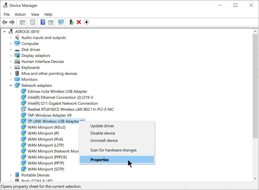
- Click the Advanced tab to configure the advanced settings.
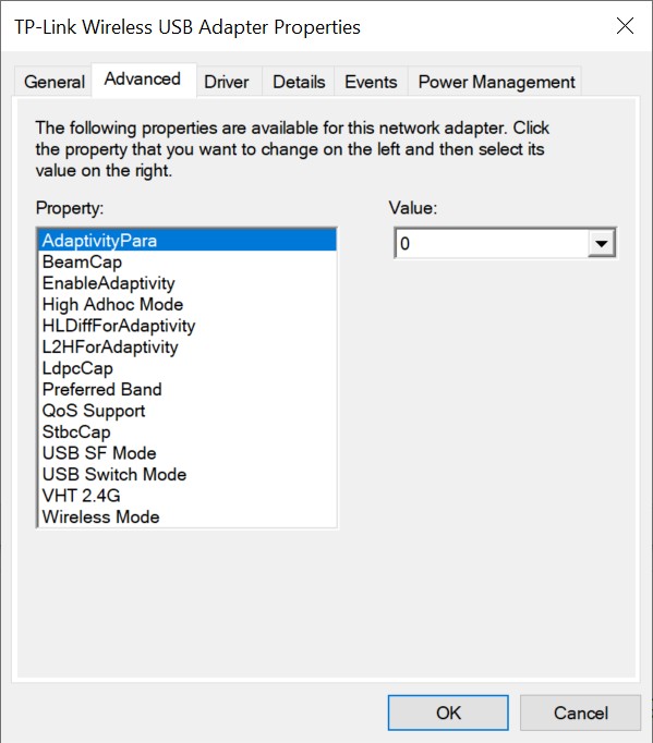
TP-Link WiFi USB adapter Default Settings
This is the default settings –
- AdaptivityPara = “0”
- BeamCap = “BEAM Disable”
- EnableAdaptivity = “Auto”
- High Adhoc Mode = “Disable”
- HLDiffForAdaptivity = “7”
- L2HForAdaptivity = “Auto”
- LdpcCap = “VHT LDPC TX|HT LDPC TX “
- Preferred Band = “No preference”
- QoS Support = “Support QoS”
- StbcCap = “VHT STBC TX|RX & HT STBC TX|RX “
- USB SF Mode = “Disable”
- USB Switch Mode = “Auto”
- VHT 2.4G = “Enable”
- Wireless Mode = “Auto”
Tplink WiFi USB adapter Custom settings 1
This is the setting that I recommend to be used by most users.
- Disable LdpcCap feature.
- Disable STBC feature.
- Disable VHT in 2.4 Ghz band.
Other than Default settings you may change these settings :
- AdaptivityPara = “0”
- BeamCap = “BEAM Disable”
- EnableAdaptivity = “Auto”
- High Adhoc Mode = “Disable”
- HLDiffForAdaptivity = “7”
- L2HForAdaptivity = “Auto”
- LdpcCap = “Disable LDPC”
- Preferred Band = “No preference”
- QoS Support = “Support QoS”
- StbcCap = “STBC Disable”
- USB SF Mode = “Disable”
- USB Switch Mode = “Auto”
- VHT 2.4G = “Disable”
- Wireless Mode = “Auto”

TP-Link WiFi USB adapter Settings 2
The beamforming ( BeamCap) feature is turned ON. Beamforming could be helpful if few devices are connected to the WiFi router. Make sure that Explicit Beamforimg is Enabled in the Wifi router if this setting is available in it.
To use the Beamforming feature
- AdaptivityPara = “0”
- BeamCap =”VHT BEAM TX|RX”
- EnableAdaptivity = “Auto”
- High Adhoc Mode = “Disable”
- HLDiffForAdaptivity = “7”
- L2HForAdaptivity = “Auto”
- LdpcCap = “Disable LDPC”
- Preferred Band = “No preference”
- QoS Support = “Support QoS”
- StbcCap = “STBC Disable”
- USB SF Mode = “Disable”
- USB Switch Mode = “Auto”
- VHT 2.4G = “Disable”
- Wireless Mode = “Auto”
TP-Link WiFi USB adapter Settings 3
“Preferred Band” setting of the TP-Link wifi adapter is used when the WiFi network has been configured for roaming.
If you want the TPlink wifi adapter to prefer connecting to 5 Ghz band in the roaming network then use the setting.
- Preferred Band = “5G First”
If you want the TPlink wifi adapter to prefer connecting to 2.4 GHz band in the roaming network then use the setting.
- Preferred Band = “2.4G First”
TP-Link Mini Wireless USB Adapter settings
- AP Mode Force BW20 : Enable
- IEEE802.11h :
- Disable : This option is recommended when the WiFi adapter is being used in countries other than European Union. Though using this option is not necessary.
- Enable : This option is recommended when the WiFi adapter is being used in European Union.
- Multimedia/Gaming Environment: Enable
- Prefer 5G : Enable
- Roaming Sensitivity:
- Lowest: Choose this option if the WiFi-enabled device does not roam and remains stationary throughout the day.
- Low: Choose this option if the WiFi-enabled device roams sometimes throughout the day. The WiFi adapter will scan for other WiFi networks with the same SSID when the signal strength of the currently connected WiFi network drops below the Low level.
- Medium: Choose this option if the WiFi-enabled device roams a lot throughout the day. The WiFi adapter will scan for other WiFi networks with the same SSID when the signal strength of the currently connected WiFi network drops below the Medium level.
- Selective suspend: Disable
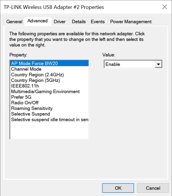
Realtek Wireless LAN 802.11n Settings
- 802.11d : Enable
- Bandwidth : 20_40 MHz
- Beacon Interval: 100 ; This setting will be used when this Wifi adapter is used to host a Hotspot.
- Preamble Mode: Short
- Roaming Sensitivity Level : Middle
- Wireless Mode : Auto
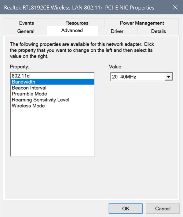
Edimax Wireless USB adapter 802.11n Settings
- AP Mode Force BW20 : Enable
- Multimedia/Gaming Environment : Enable
- Randio On/Off : Enable
- Roaming Sensitivity :
- Lowest: Choose this option if the WiFi-enabled device does not roam and remains stationary throughout the day.
- Low: Choose this option if the WiFi-enabled device roams sometimes throughout the day. The WiFi adapter will scan for other WiFi networks with the same SSID when the signal strength of the currently connected WiFi network drops below the Low level.
- Medium: Choose this option if the WiFi-enabled device roams a lot throughout the day. The WiFi adapter will scan for other WiFi networks with the same SSID when the signal strength of the currently connected WiFi network drops below the Medium level.
- Selective suspend: Disable

Intel Wireless AC 9560
- Channel Width for 2.4 GHz : Auto
- Channel Width for 5 GHz : Auto
- Fat channel intolerant : Enabled
- Global BG Scan blocking : On Good RSSI
- MIMO power save mode : No SMPS
- Preferred band : Prefer 5GHz band
- Roaming Aggressiveness:
- Lowest: Choose this option if the WiFi-enabled device does not roam and remains stationary throughout the day. This effectively disables roaming.
- Medium-low: Choose this option if the WiFi-enabled device roams sometimes throughout the day. The WiFi adapter will scan for other WiFi networks with the same SSID when the signal strength of the currently connected WiFi network drops below the Medium-Low level.
- Medium: Choose this option if the WiFi-enabled device roams a lot throughout the day. The WiFi adapter will scan for other WiFi networks with the same SSID when the signal strength of the currently connected WiFi network drops below the Medium level.
- Throughput Booster : Disabled
- Transmit Power : Highest
- U-APSD: Disable

Intel Centrino(R) Avanced-N 6205
- 802.11n Channel Width for band 2.4 GHz : Auto
- Mixed mode protection: RTS/CTS Enabled
- Preferred band : Prefer 5.2 GHz
- Roaming Aggressiveness:
- Lowest: Choose this option if the WiFi-enabled device does not roam and remains stationary throughout the day. This effectively disables roaming.
- Medium-low: Choose this option if the WiFi-enabled device roams sometimes throughout the day. The WiFi adapter will scan for other WiFi networks with the same SSID when the signal strength of the currently connected WiFi network drops below the Medium-Low level.
- Medium: Choose this option if the WiFi-enabled device roams a lot throughout the day. The WiFi adapter will scan for other WiFi networks with the same SSID when the signal strength of the currently connected WiFi network drops below the Medium level.

Brostrend 802.11 AC
- AP mode Force BW20 : Enable
- Channel Mode: 2.4G + 5G
- IEEE802.11h : Enable
- Multimedia/Gaming Environment : Enable
- Prefer 5G : Enable
- Roaming Sensitivity:
- Lowest: Choose this option if the WiFi-enabled device does not roam and remains stationary throughout the day.
- Low: Choose this option if the WiFi-enabled device roams sometimes throughout the day. The WiFi adapter will scan for other WiFi networks with the same SSID when the signal strength of the currently connected WiFi network drops below the Low level.
- Medium: Choose this option if the WiFi-enabled device roams a lot throughout the day. The WiFi adapter will scan for other WiFi networks with the same SSID when the signal strength of the currently connected WiFi network drops below the Medium level.
- Selective Suspend: Disable
- Country Region (2.4GHz):
- To support all channels select : (1 – 14)
- For USA and Canada : (1 – 11)
- For other countries : (1 – 13)
- Country Region (5GHz):
- For USA, Hong Kong, Australia, New Zealand, South Korea and Canada : (36 – 165)
- For European countries : (36 – 140)
- For Taiwan : (52 – 161)
- For China : (36 – 48, 149 – 165)
- Japan : (36 – 140)
- To support all channels select : (36 – 165)

Other Setting you may see in wifi adapters
- Channel Width for 2.4 GHz : Auto
- Channel Width for 5 GHz : Auto
- 802.11n Channel Width for 2.4ghz: Auto
- 802.11n Channel Width for 5.2ghz: Auto
- Roaming Tendency: Off
- Throughput Booster/Throughput Enhancement: Disabled
- Transmit Power : Highest
- Preferred band : Prefer 5GHz band, Prefer 5.2 GHz band, Prefer 5G First
- Fat Channel Intolerant : Enabled
- VHT 2.4G IOT : Disable
- VHT 2.4G : Disable
- WiFi Config : Performance
- ARP offloading for WoWLAN : Enabled
- GTK rekeying for WoWLAN: Enabled
- Global BG scan blocking: Always
- Mixed-mode protection: RTS/CTS Enabled
- Packet Coalescing: Enabled
- MIMO Power Save Mode : No SMPS
- Power Saving Mode: Maximum Performance
- Power Output: 100%
- WiFi configuration: performance
- USB switching mode: automatic
Settings for Low latency
Network Low latency is required especially for fast-paced games where reaction time is important. This will
To achieve low latency do the following in the WiFi adapter setting:
- Disable beamforming: Beamforming feature in the 802.11ac network will add to latency.
- Disable STBC:
- Disable LDPC:
- U-APSD Support: Disable
Other Useful Links:
- Tips to increase WiFi speed : https://www.intel.in/content/www/in/en/tech-tips-and-tricks/how-to-increase-wifi-speed.html
- Quick Checks to Improve or Fix Wi-Fi Connection Issues
- Improving wireless range : https://kb.netgear.com/1114/Improving-wireless-range-Overview
- Cause of poor signal strength due to obstructions and interference: https://www.linksys.com/ca/support-article?articleNum=141729
- Key Features of 802.11ac
- Channel Planning Best Practices for Better Wi-Fi
- Picking best location for antennas : https://kb.netgear.com/1032/Picking-best-location-for-antennas
- Common Sources of Wireless Interference : https://documentation.meraki.com/MR/WiFi_Basics_and_Best_Practices/Common_Sources_of_Wireless_Interference
- How to improve the speed of TP-Link wireless adapters : https://www.tp-link.com/us/support/faq/709/
- Different Wi-Fi Protocols and Data Rates : https://www.intel.com/content/www/us/en/support/articles/000005725/network-and-i-o/wireless.html
- Netgear – How do I troubleshoot my wireless network
- Netgear: How do I troubleshoot wireless networking setup issues?
- 802.11ac MCS rates
- Wi-Fi 4/5/6/6E (802.11 n/ac/ax)
- What Are 802.11ac and 802.11ac Wave 2?
- 10 tips to help improve your wireless network

This post is pretty cool! I use a D-Link DWA-171 AC600 MU-MIMO and i love this tips, can have other tips for my adapter or suggestions to improve the performance?
10/10 Fantastic guide for wifi adapter settings
Very useful and detailed explanation. I arrived looking to know what the Adaptivity settings were for. Using a small “Tenda” usb nic, Realtek 8811CU, with usb extension lead. Was seeing 40Mbps on wireless mode Auto. After changing to 802.11ac, speed jumps to 170Mbps. Seems it does not use the 5GHz by default. Thank you for this most interesting article.
Где узнать про adaptivity para wifi что это 0 или 1
Хочу купить adaptivity para wifi что это 0 или 1
WOW….(A++)!! If that’s even a legal grade (lol)
Truly “the MOST HELPFUL” form of assistance I’ve ever received online or in person (based on this specific subject matter). I mean I printed “2” copies of this webpage & highlighted the info needed:
– 1 for the game room
– 1 for my stay-at-home office
Can’t thank you all at “CYBER RAIDEN” enough so I figured 5 minutes explaining my gratitude & officially becoming a new member is a given. This webpage is thuro, informative, easily understood, uniquely designed (for those just wanting too get to their specific point), and I’ve supperceeded my task at hand.
Thanks Again “CYBER RAIDEN,”
Sincerely,
Cameron
THIS is the best most understandable and comprehensive guide ive found anywhere on this subject! Its a very widespread topic that has left many of us guessing as there isnt any explanations for determining what these settings do and leave many of us thinking that we need to go spend more money or our adapters are broke. Im so grateful someone took the time and was very methodical in covering most if not all aspects and options involved. Thank you so much my guy! I wil pass along the knowledge and share the crap out of this! YOUAREAMAZING!!
THANK YOU! I agree with everyone else – this guide is by far the best, most comprehensive one I’ve come across and you have answered questions I’ve been trying to get answered for years. You convey the information very clearly, it’s easy to follow and understand. Thank you again for a great lesson in wifi adapter settings!
Thanks Very informative and will serve me well for future reference
I was skeptical about setting it to n mode instead of ac mode but it really helped to reduce the upload latency by 100%, great guide and thank you