Modelling Air Compressibility in OWC Devices with Deformable Air Chambers


MaREI Centre, Beaufort building, University College Cork, Haubowline Road, Ringaskiddy, P43C573 Co. Cork, Ireland
*
Author to whom correspondence should be addressed.
J. Mar. Sci. Eng. 2019, 7(8), 268; https://doi.org/10.3390/jmse7080268
Submission received: 22 July 2019
/
Revised: 31 July 2019
/
Accepted: 8 August 2019
/
Published: 11 August 2019
(This article belongs to the Special Issue Advances in Ocean Wave Energy Conversion)
Abstract
:Air compressibility effects play an important role in large-scale Oscillating Water Column (OWC) wave energy converters. Air compressibility is however not scalable with Froude similarity law. An existing scaling method enables correctly reproducing the air compressibility at the model scale, but its implementation is effortful and becomes cumbersome for floating devices and tests at relatively large scales (1/15th–1/2th). Air compressibility is therefore commonly ignored in model-scale tank testing of conventional OWC devices, which can lead to substantially unrealistic results on the device performance relative to the full-scale device. In the case of the Tupperwave device, which is a closed circuit OWC device, correctly modelling air compressibility during tank testing is however essential because the device relies on air compressibility to work. In this paper, a new method for modelling air compressibility at the model scale is presented. The method uses variable volume chambers, which mimic air compressibility by storing energy under the form of strain energy. This method reduces the difficulties of implementation and enhances the application of the existing method to larger scales. Various applications to this method are identified and described, including the presentation of a novel OWC concept.
1. Introduction
Model-scale physical testing is essential in the development of wave energy converters and especially for the advancement through the Technology Readiness Levels (TRLs) [1]. Oscillating Water Column (OWC) devices are a major class of wave energy converters that have been the object of extensive research and development effort over many years, including the deployment of prototypes at sea [2]. The OWC converter consists of a hollow (fixed or floating) structure, open to the sea below the water surface. Wave action alternately compresses and decompresses the air trapped above the inner water free-surface in the OWC chamber, converting wave energy into pneumatic energy. Different types of OWC devices can be distinguished on the basis of their working principle for harnessing the pneumatic energy. The most commonly-studied type of OWC device, which will be referred to as the conventional type in the rest of the paper, is equipped with a self-rectifying turbine located on top of the OWC chamber and connecting it with the atmosphere. The compression and decompression of the air in the OWC chamber forces air in and out of the chamber through the turbine, which is coupled to a generator. Self-rectifying turbines are able to harness both directions of air flow, but there efficiency is lower than a unidirectional turbine. Conventional OWC devices have been installed on the shoreline, standing near shore on the sea floor, incorporated into breakwaters or deployed offshore as floating structures. Other types of OWC devices use non-return valves to rectify the air flow across a unidirectional turbine. Various flow-rectifying OWC devices have been studied, such as Masuda’s navigation buoy [2], the Kaimei [3], the Leancon [4], the vented OWC from Wave Swell Energy [5] and the Tupperwave device [6], all using different air flow rectification methods for rectifying the air flow.
In a full-scale conventional OWC device, the compressibility of the air in the OWC chamber acts as a brief storage of energy and introduces a phase shift between the air flow rate displaced by the water column and the flow rate across the turbine. This effect is called the spring-like effect and plays an important role in large-scale OWC devices [7] and especially on the dynamic motion of the water column relative to the device structure. For accurate modelling of an OWC device, either numerically or physically, the spring-like effect of air needs to be taken into account.
Numerically, the modelling of air compressibility is easily achievable by using the linearised isentropic relationship between air density and pressure [8]. Physically, modelling air compressibility in model-scale OWC devices can be demanding. Hydrodynamic similarity at model scale is commonly achieved using Froude scaling, which respects the geometrical similarity of the underwater part of the device by multiplying all geometrical dimensions by the Froude scaling factor . Air compressibility in an air chamber is however not scalable with the Froude similarity law. It was recognized in [9] that, to scale adequately air compressibility in an air chamber, the ratio between the air chamber volume of the model and full-scale device has to be equal to and not to as the Froude similarity would suggest. The required volume for the chamber is therefore a lot bigger than the volume suggested by Froude similarity. The solution to implement this method, without changing the geometry of the device on the water, is to connect the device chamber to an external reservoir of the required volume with a pipe, as was done in [9,10] on small bottom-fixed conventional OWC devices.
Implementing this method on a floating OWC devices is particularly difficult because the connection of a stationary air volume with the floating OWC may introduced elastic, damping and inertia forces associated with the motion and deformation of the flexible pipes. The difficulty of implementing this method increases with the scale of the tested device because the volume of the additional reservoirs increases with the square of the scaling factor. The method quickly becomes unpractical.
Moreover, this method introduces another dissimilarity between the full-scale device and the physical model: the relative volume change of the OWC chamber due to the elevation of the internal water column becomes much smaller in the physical model than in the full-scale device, thus omitting non-linearities due to significant volume changes in the full-scale device [11].
Since the spring-like effect of the air in conventional OWC chambers is not fundamental to the working principle, it is often neglected in tank testing. Certain types of OWC devices do however rely on air compressibility to work, and the correct modelling of air compressibility at model scale is therefore important. This is the case for the Tupperwave device, which was physically tested at 1/24th scale [12]. The Tupperwave device is a floating OWC device, and more than three cubic meters of additional air reservoirs are connected to the floating device, making the testing particularly challenging.
The practical implementation difficulty of modelling air compressibility at model scale using additional fixed volume air reservoirs motivates the search for other approaches. In the present paper, a method for modelling air compressibility in OWC devices using deformable volume chambers is presented. The chamber deformation mimics the air compression or decompression by storing energy under the form of strain energy. A similar idea was already mentioned in [13]. Section 2 of this paper mathematically demonstrates the possibility of modelling air compressibility happening in a large air chamber using a smaller chamber with slightly deformable walls. Section 3 describes the effect of deformable air chambers observed during the model scale testing of the Tupperwave device. Section 4 finally identifies practical applications to the new method and presents a new concept of OWC.
2. Deformable Volume Air Chamber
Consider the following open thermodynamic system: an air chamber containing a mass m of air at the density and at pressure . The air mass flow rates and flow respectively in and out of the chamber. They are functions of the air excess pressure . It is assumed that the transformations are slow enough for the thermodynamic state of air in the chamber to be uniform. The volume of the chamber is elastically deformable, and the chamber walls have no inertia. Hence, evolves linearly with the excess pressure such that:
where is the initial volume of the chamber when the inner pressure equals atmospheric pressure and C is the chamber deformation coefficient in . We note that the excess pressure can either be positive or negative. A dot over a variable indicates the variable’s derivative taken with respect to time.
It is assumed that in the pressure conditions considered, the volume variation of the chamber remains small compared to the initial volume:
and the air density variation remain small compared to atmospheric density:
Neglecting second order terms, the mass conservation equation in the system is:
Equation (4) informs that the variation of mass in the chamber is the sum of two phenomena: air density variations (compressibility) and chamber volume variations.
The mass balance equation gives:
where and are the air mass flow rates flowing respectively in and out of the chamber.
If the system is considered adiabatic and the transformations slow enough to be reversible, the transformations become isentropic, and consequently, we may write:
where is the air heat capacity ratio. Moreover, in the case where the excess pressure remains small compared to the atmospheric pressure, it is possible to linearise the isentropic relationship between density and pressure. Once linearised, Equation (6) leads to:
and to:
Using Equations (4), (5), and (8), the pressure variation in the deformable chamber can be written as:
Finally, using the derivative of Equation (1) in Equation (9), we can write:
We now consider a larger air chamber of fixed volume , subjected to the same incoming and outcoming mass flow rates and . is the air pressure in this chamber. being a fixed volume, the mass variation of air in the chamber is only made possible by the compressibility of the air:
In a like manner as Equation (9), the pressure variation in the fixed volume chamber is:
By analogy to Equations (10) and (12), it is clear that the pressures in the elastically-deformable chamber and in the fixed volume chamber will evolve in the same way if:
It is thus possible to mimic air compressibility effects happening in a large fixed volume chamber of volume while using a smaller chamber of volume , which is slightly elastically deformable with a deformation coefficient C. It is however important to keep in mind that the conditions given by Equation (2) and (3) need to be respected. The possibility of using variable volume air chambers to model air compressibility effects in larger fixed volume chambers finds an application in model-scale testing of OWC devices. In the next section, the effect of air chamber volume variation is observed in a practical case.
3. Tank Testing of the Tupperwave Device
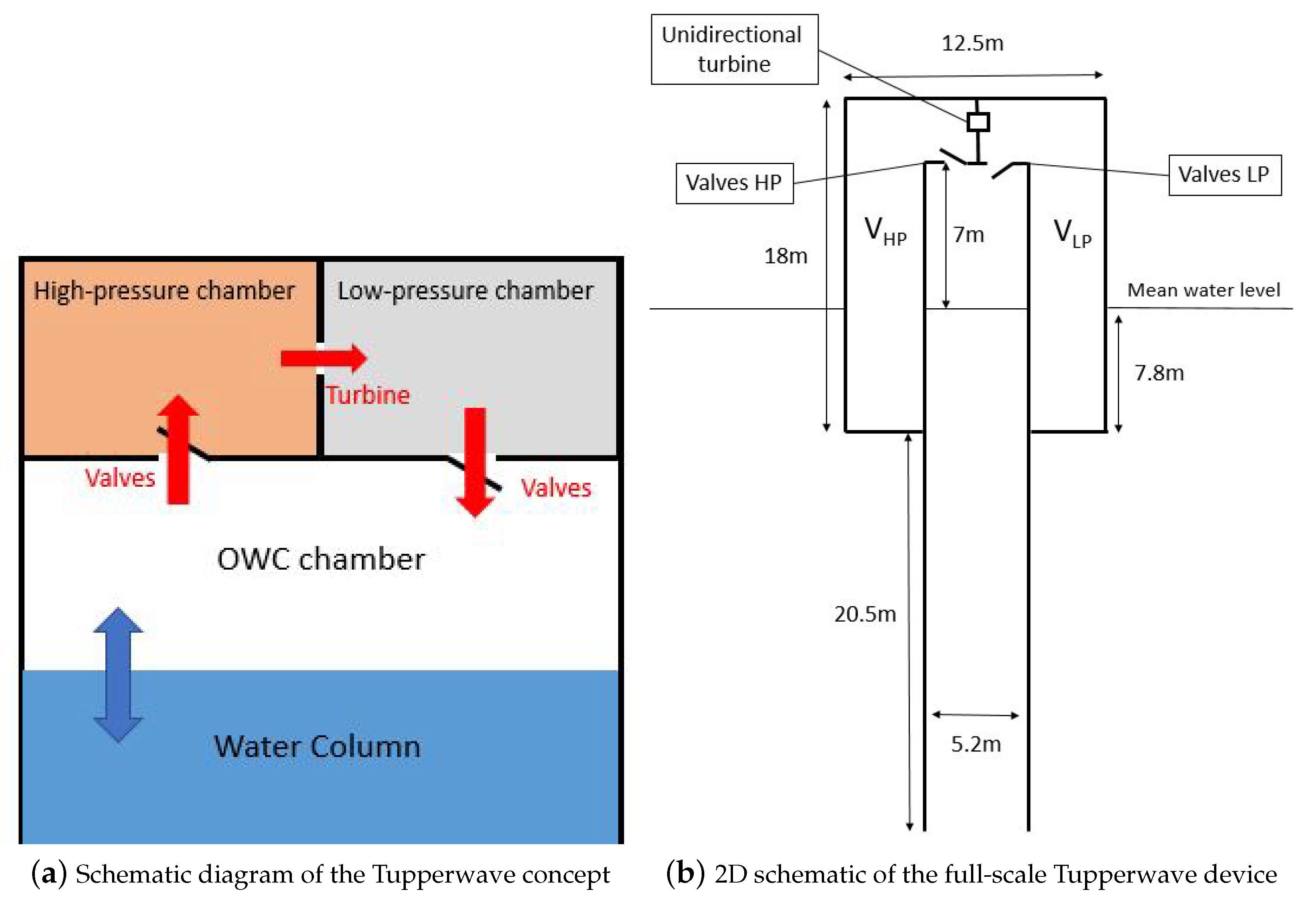
The Tupperwave concept is a flow-rectifying OWC working in closed-circuit, which uses non-return valves and two large fixed volume chambers acting as accumulators. Figure 1a displays a schematic of the Tupperwave working principle: when the water column rises, air is compressed in the High-Pressure (HP) chamber, and when the water falls, the air is sucked from the Low-Pressure (LP) chamber. The continuous oscillatory motion of the water column creates a pressure differential between the HP and LP chambers, which creates a smooth unidirectional flow across the unidirectional turbine located in between. The Tupperwave working principle was studied in [6] and applied to a floating spar buoy. Figure 1b displays the geometry of the full-scale Tupperwave device. The volume of the HP and LP chambers has a constant value of each, providing also buoyancy volume.
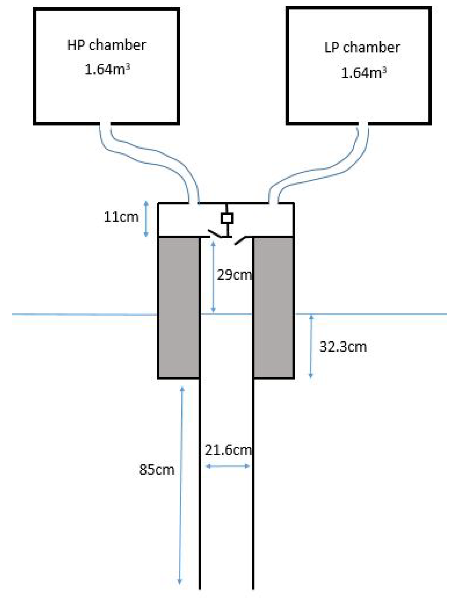
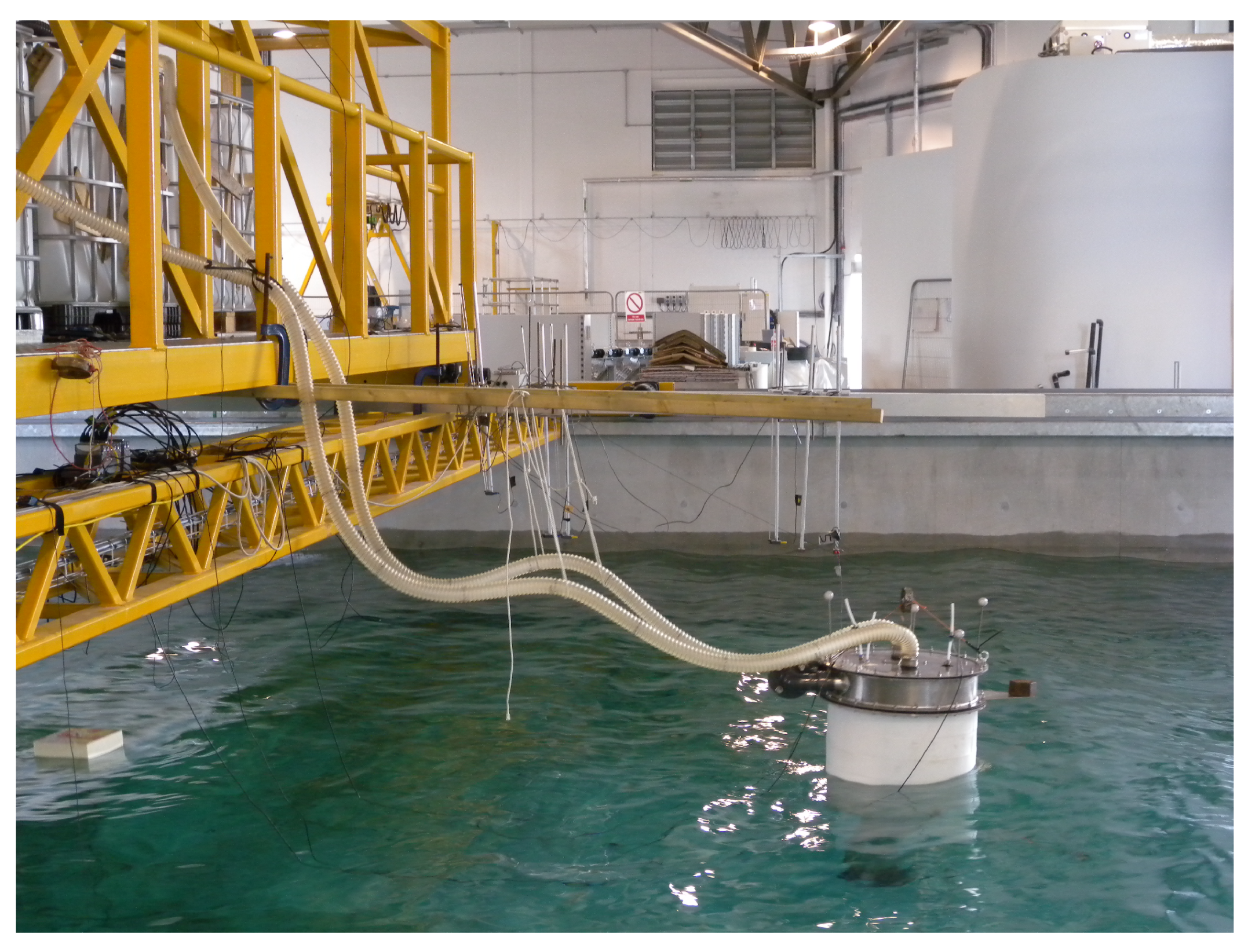
The Tupperwave working principle entirely relies on air compressibility in the HP and LP chambers. For this reason, it is essential to reproduce correctly air compressibility in the two chambers at model scale. The device was physically modelled and tested at scale. The experiments took place at the Lir-National Ocean Test Facility (Lir-NOTF) of the MaREI centre in Cork, Ireland. The device was tested under regular and irregular sea states in the Deep Ocean Basin, which is 35 m long, 12 m wide, and 3 m deep. More details on the device fabrication and test setup can be found in [12]. The exact Froude scaling ratio was . To reproduce air compressibility, the volumes of the chambers on the model were scaled by and were each. Unlike for the full scale, it is impossible to fit both chambers on the device as their volume largely exceeds the overall volume of the device. The alternative at small scale is to locate the main volume of the HP and LP chambers outside of the device and connect them to two smaller chambers on the device with flexible pipes. Large reservoirs were used for the HP and LP chambers and located on the pedestrian bridge above the tank. Figure 2 displays the schematic of the device with the external reservoirs. The flexible pipes were chosen as lightweight and flexible as possible to reduce their influence on the floating device motion. Part of the pipes’ weight was supported by bungee ropes; see Figure 3.
It is important to note that the modelling of the air compressibility effects in the OWC chamber was omitted during the experiment since it is not essential in the device working principle. In the case of conventional OWC devices, it is well-established that failure to model air compressibility effects results in an over-estimation of the device performance [7,14,15]. In the case of the Tupperwave device, similar consequences are expected. However, modelling the air compressibility in the OWC chamber of the Tupperwave device would have increased the difficulty of the testing, as it would have required one more additional chamber on the bridge and one more flexible pipe linking the device to the chamber. Such a level of complexity to model the spring-like effect in the OWC chamber was not required at this stage of development.
A numerical model of the device was developed in [6] and validated using the physical model results in [16]. The numerical model did not take into account the presence of the flexible pipes (mass, inertia, elasticity, …), but provided good prediction of the physical model hydrodynamic behaviour. This showed that such effects due to the presence of the pipes were negligible.
The results of the initial version of the numerical model, assuming fixed volumes for the HP and LP chambers, did however not predict the pressure evolution in the chambers correctly. The reason for this was that the reservoirs used for the HP and LP chambers of the Tupperwave physical model did not have perfectly-rigid walls. During the tests, it was observed that the reservoir walls moved by a few millimetres proportional to the pressure building inside the chambers. The HP chamber was observed to inflate with the build-up of a positive excess pressure inside, and the LP chamber was observed to deflate due to the negative excess pressure inside. This required a correction in the numerical model to take into account the slight volumetric change of the HP and LP chambers. An elastic deformation of the chambers, a function of the excess pressure, was added to the numerical model such that:
where is the initial volume of the chambers and C is the chambers’ deformation coefficient assessed empirically. The value of was calibrated using the experimental results and was obtained by an iterative process to minimise the error with the experimental results in the different tested irregular sea states.
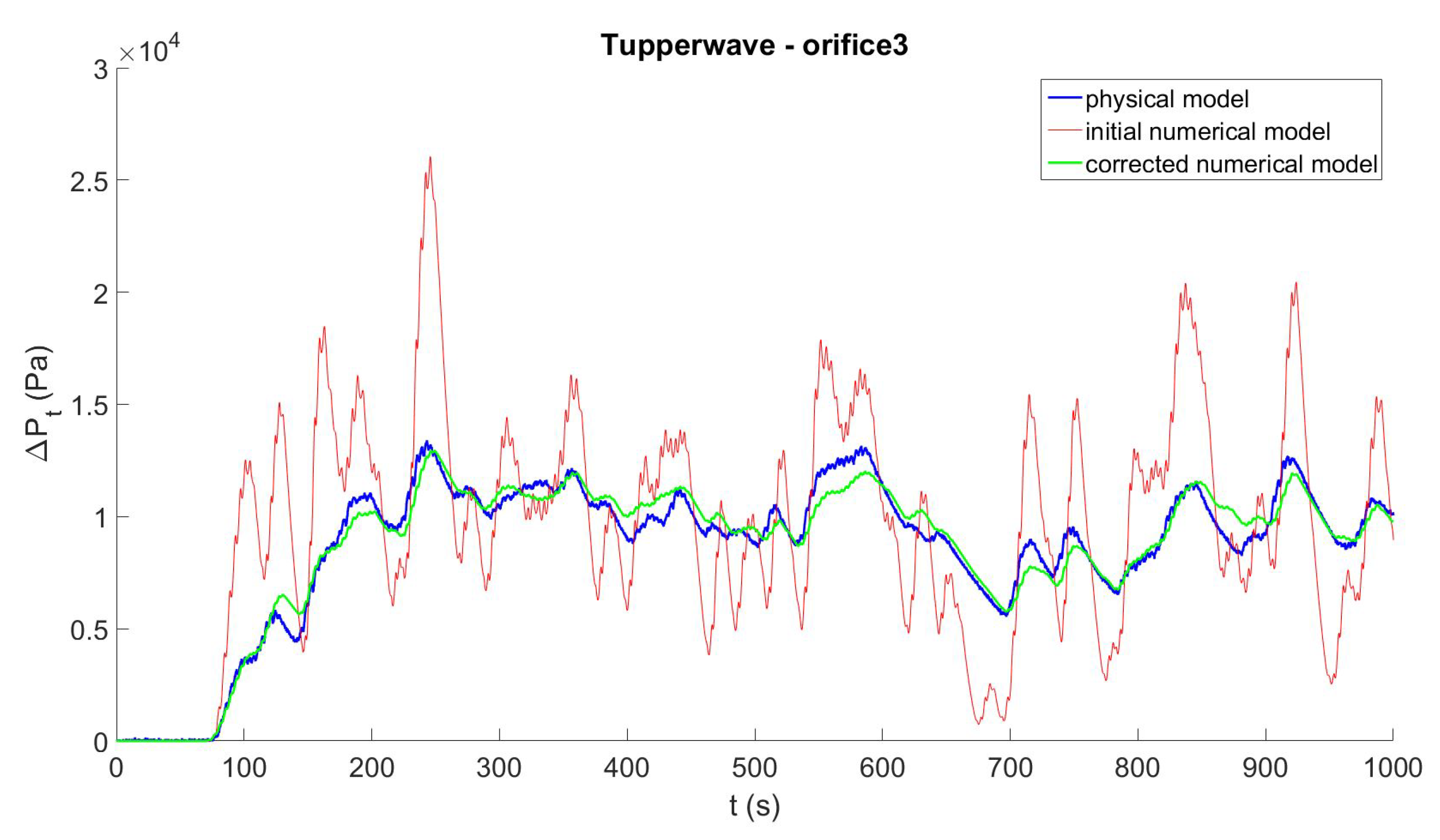
Figure 4 compares the time series of the pressure drop across the orifice of the Tupperwave device in the irregular sea state { m; s} obtained by the physical model, the initial numerical model, and the corrected model. Results are given at full-scale equivalence to give the reader perspective. The pressures in the rigid-wall chambers from the initial numerical model varied quicker with the wave groups than in the chambers used in the physical tests. As a result of the chambers’ deformation, an extra smoothing effect of the pressure variations between the wave groups was observed in irregular waves. It is clearly shown in [16] that the corrected numerical model, which accounts for the small volume variations of the HP and LP chambers, enhanced the fidelity with the physical model.
From an energy transfer perspective, the pneumatic energy stored in the HP and LP chamber was not only stored in the form of pressure, but also in the form of strain energy. This explains the lower pressure variations between wave groups. The strain energy stored by the elastic chamber deformation is recoverable. This is why the average value of the pressure drop across the orifice was not impacted.
According to Equation (13), the HP and LP deformable chambers of the physical model were actually behaving as if they were fixed volume chambers of volume:
and, therefore, modelling full-scale fixed volume HP and LP chambers of volume:
which is not what was intended in the first place, but explains the smoother evolution of the pressures in the chambers.
This experience constitutes the first (involuntary) physical implementation of the method suggested in Section 1 to model large fixed volume air chambers using smaller deformable air chamber. The device modelled was therefore not exactly the intended one, but the cause was understood and reproduced numerically.
In the next section, applications for deformable air chambers are identified, and the observations made in the present section are turned into opportunities.
4. Possible Applications
Deformable air chambers in OWC devices can either be used for air compressibility modelling purposes in scaled physical modelling of OWC prototypes or directly integrated in the working principle of full-scale OWC device.
4.1. Modelling of Air Compressibility
4.1.1. Deformable Chamber on the Scaled Device
The main advantage of using deformable volume chambers over fixed volume chambers for the modelling of air compressibility is their substantially smaller volume. If well designed and sufficiently small, the deformable chamber can directly be used on the device, respecting geometrical similarity with the full-scale device and hence the relative volume change due to the motion of the water column. This is of particular interest for floating devices because it avoids the use of additional external chambers and flexible pipes. It is however obvious that the design and calibration of a custom deformable air chamber to the device geometry requires considerable efforts and is therefore only relevant in relatively large-scale testing.
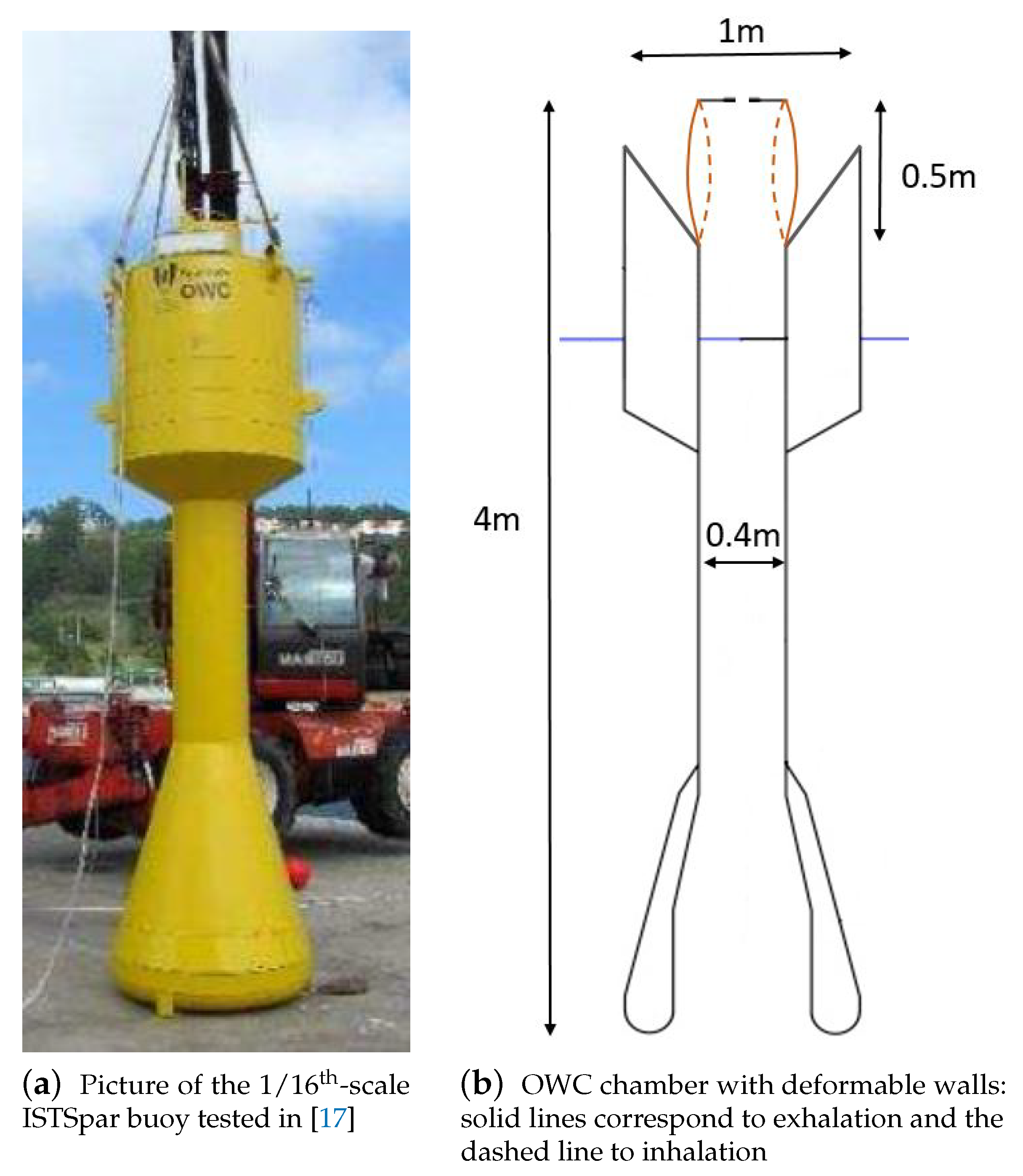
A practical example would be for the testing of the IST Spar buoy at 1/16th scale (), which was tested in [17]. The full-scale OWC chamber had a volume , which is equivalent to when scaled geometrically. The full-scale air chamber should however be modelled by a fixed volume in order to scale air compressibility correctly. This volume is too large to fit on the device, and the use of an additional external air chamber located outside of the device and connected to the device by flexible pipe is unpractical at this scale. Hence, the physical modelling in [17] omitted the reproduction of air compressibility in the OWC chamber. Figure 5a displays a schematic of the device as tested. The construction of the upper part of the cylindrical OWC chamber with a deformable walls, as presented in Figure 5b, is a potential solution to model the spring-like effect of the air. Obviously, the deformable chamber can be designed in different ways, using either deformable material (polymer membrane, plastic or a flexible bellows) or a mechanical piston combined with a spring. The chamber deformation coefficient is easily assessed using Equation (13):
Assuming that the maximum excess pressures achieved in the OWC chamber during the tests are Pa (equivalent to 20,000 Pa at full scale), the diameter of deformable cylindrical part of the OWC chamber would change by cm.
4.1.2. Tunable External Deformable Chamber
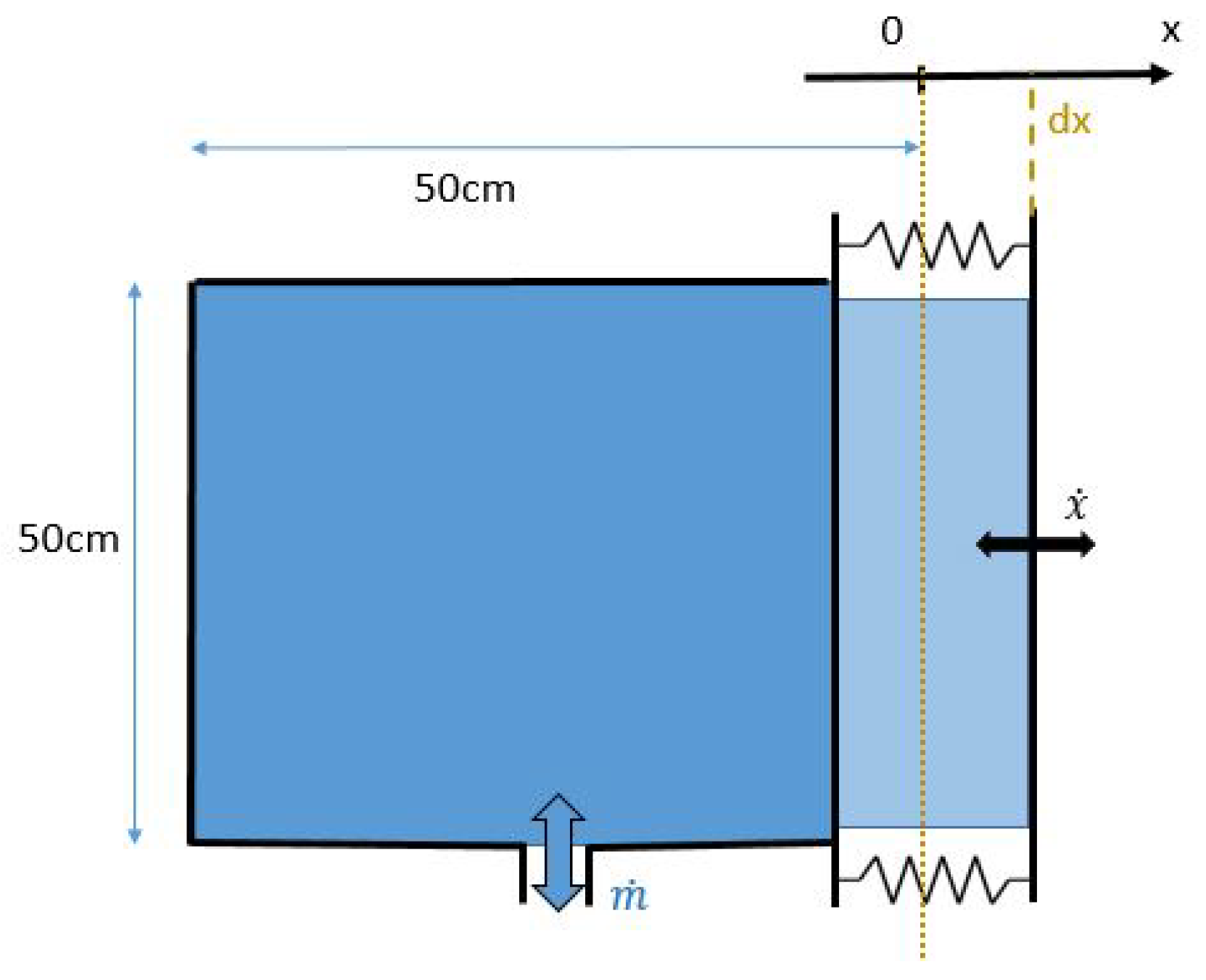
For smaller scale devices, the use of additional fixed volume external chambers connected with flexible pipes is achievable, as seen in Section 3. The volume of a given fixed volume chamber is tunable by filling the chamber with water, but the tuning remains limited, and the volume of the additional chamber may become quite large for large models. The use of a deformable chamber can considerably reduce the volume. Moreover, if the chamber’s deformation coefficient is tunable (with the help of mechanical springs for example), the same chamber can be used to model a wide scope of fixed volume chambers.
Figure 6 displays the schematic of a cm chamber that deforms elastically as one of the walls moves along the x-axis. The chamber’s deformation coefficient is adjustable with mechanical springs. We note that the inertia of the moving wall needs to be small enough to react quickly to a sudden change of pressure in the chamber. This deformable chamber can be used to model the HP and LP chambers of the Tupperwave device at various scales. The HP and LP chambers of the full-scale Tupperwave device were each, and it was considered that the maximum excess pressure achieved in the chambers was . Table 1 gives, for various scaling factors, the required chamber deformation coefficient C and maximum deformation achieved under maximum pressure. The table also gives the necessary volume if fixed volume chambers were to be used.
Hence, the same deformable chamber can be used in different experiments for various scales and is relevant in a centre that is likely to carry out many experiments.
4.2. The Uilleann WEC
Variable volume air chambers find also application in full-scale OWC Wave Energy Converters (WEC) giving birth to a new concept for an OWC device, named by the authors as the Uilleann WEC. The working principle of the Uilleann WEC is similar to that of the Tupperwave device, but uses variable volume air chambers for the HP and LP chambers instead of fixed volume chambers.
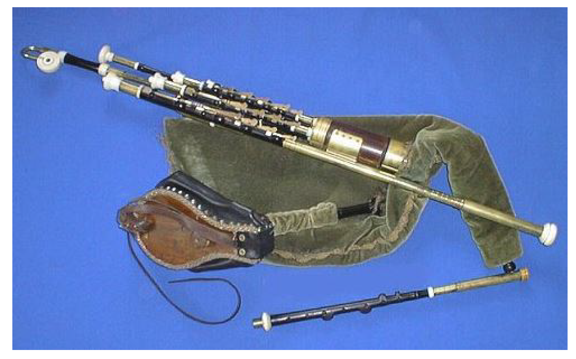
The Uilleann pipes are the characteristic national bagpipes of Ireland. The player uses a bellow strapped around the left elbow and the waist to inflate the main bag, held under the right elbow. At the same time, the player gently presses the main bag with his/her right elbow and slowly empties the main bag through the pipes, providing a smooth and continuous air flow. A picture of a set of Uilleann pipes is displayed in Figure 7. The alternative pneumatic power generated by the below under the right elbow is accumulated in the main bag and smoothly released in the pipes. The Uilleann WEC uses the same principle, hence its name.
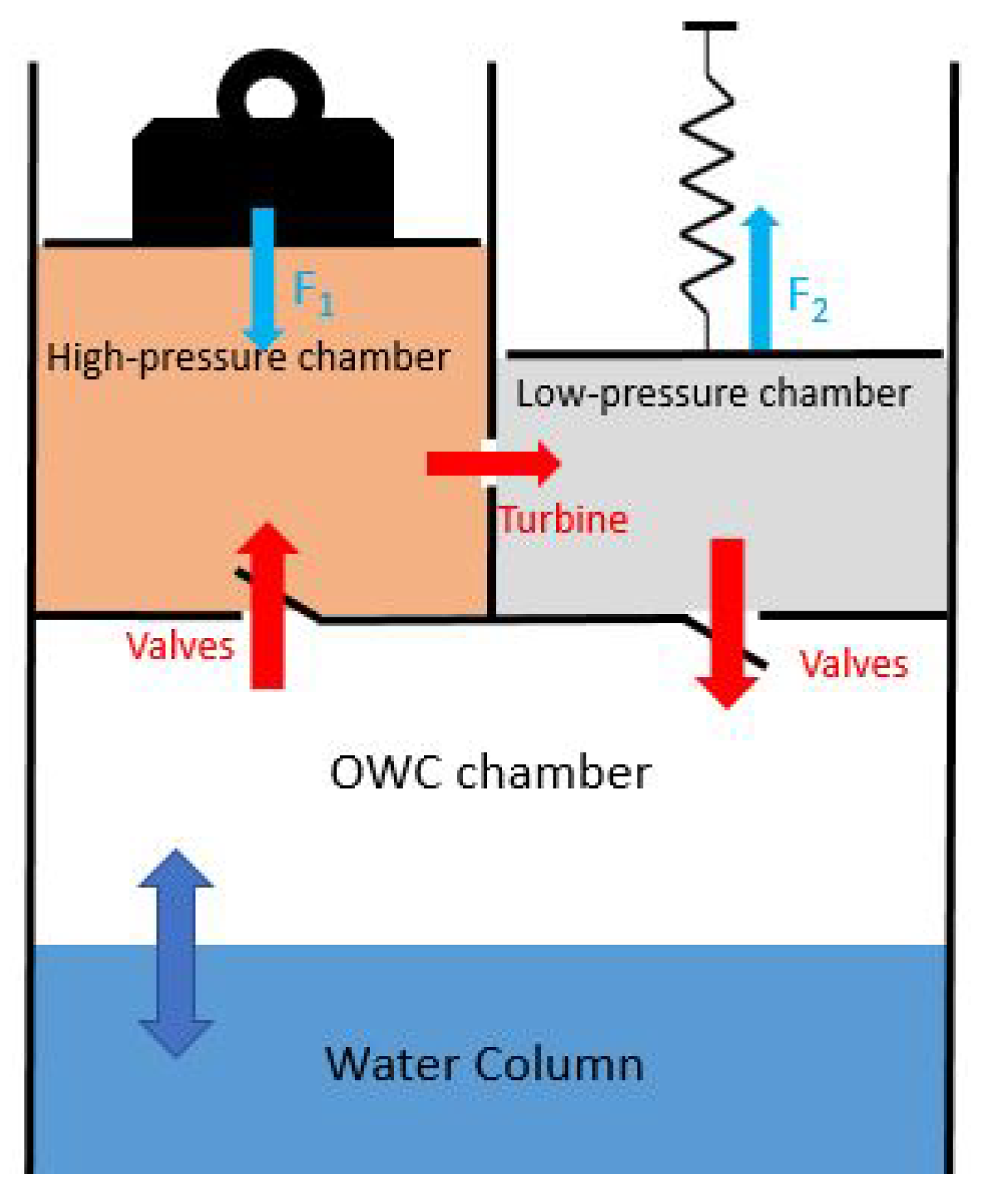
The working principle of the Uilleann WEC is displayed in Figure 8, where the HP and LP chambers are represented as piston-type variable volume chambers. The OWC chamber is equivalent to the bellows under the left elbow of the pipes’ player. The HP chamber is the exact equivalent of the Uilleann pipes’ main bag: the upward motion of the water column inflates the HP chamber, which is constantly forced to empty through the turbine due to a restoring force , symbolised as a weight. Inversely, the downward motion of the water column sucks air from the LP chamber, which is constantly forced to fill up through the turbine due to a restoring force symbolised as a spring. The alternative pneumatic power created from the motion of the water column is therefore not only stored under the form of pressure (compressibility) in the chambers, like the case in the Tupperwave device, but also under the form of strain, elastic or gravitational potential energy, depending on the deformation mechanism of the chambers.
As observed at model scale in Section 3, the additional energy-storing mechanism due to the deformation of the chambers results in a better smoothing of the pneumatic power flowing across the turbine, which will eventually enhance the electrical power quality delivered by the device. The Uilleann concept can therefore be applied to the full-scale spar buoy in Figure 1b, and a slight deformation of the chambers would enhance considerably the power quality. However, further assessment of the concept is required to determine its technical and economic feasibility at full scale and the gain in electrical power quality compared to the fixed volume chambers of the Tupperwave device.
In the Tupperwave concept, very large HP and LP chamber volumes are necessary to allow power accumulation and create decent pneumatic power smoothing [6]. The Tupperwave concept is therefore particularly suited to large floating OWC structures, which benefit from large buoyancy volume where the HP and LP chambers can be located; see Figure 1b. The application of the Tupperwave concept to onshore OWC devices is however limited due to the cost of the large HP and LP chambers construction and of the onshore space required. The Tupperwave concept is also not suitable for self-powered sensor buoys due to their small size. Due to the smaller size of the deformable chambers, the Uilleann concept opens the possibilities for the extension of closed-circuit systems to onshore OWCs and small self-powered sensor buoys, where the Tupperwave concept is not applicable. Another advantage of the closed-circuit OWC system against the conventional OWC is the reduction of noise because of no atmospheric discharge, which is very relevant for onshore OWC structures.
5. Conclusions
In the present paper, a method to reproduce air compressibility effects occurring in a large fixed volume air chamber, using a smaller, but slightly elastically-deformable chamber, is presented and mathematically analysed. A formula to assess the chamber’s deformation coefficient was found.
The use of a deformable air chamber had its first application in the scaled physical modelling of OWC wave energy devices. It was implemented involuntarily during the testing of the Tupperwave device at a 1/24th scale. This provided a first experience of the method and revealed its potential.
The combination of the Tupperwave concept with the deformable air chamber also resulted in a novel closed-circuit OWC device concept called the Uilleann WEC concept. The deformable accumulator chambers of the Uilleann WEC can be smaller than the fixed volume accumulator chambers of the Tupperwave device. For that reason, the Uilleann WEC extends the application of the closed-circuit OWC system to onshore OWC structures and self-powered buoys.
In further works, the suggested method for modelling air compressibility will be put into practice and validated for model-scale testing. Specific applications of the Uilleann WEC concept will also be investigated, and its power performance and smoothing capacities will be studied.
Author Contributions
Conceptualization, P.B.; investigation, P.B.; writing, original draft, P.B.; writing, review and editing, P.B. and J.M.; funding acquisition, J.M.
Funding
The authors would like to acknowledge funding received through the OCEANERA-NETEuropean Network (OCN/00028).
Conflicts of Interest
The authors declare no conflict of interest. The funders had no role in the design of the study; in the collection, analyses, or interpretation of the data; in the writing of the manuscript; nor in the decision to publish the results.
Abbreviations
The following abbreviations are used in this manuscript:
| WEC | Wave Energy Converter |
| OWC | Oscillating Water Column |
| HP | High Pressure |
| LP | Low Pressure |
References
- Weber, J. WEC Technology Readiness and Performance Matrix–finding the best research technology development trajectory. In Proceedings of the 4th International Conference on Ocean Energy, Dublin, Ireland, 17–19 October 2012; pp. 17–19. [Google Scholar]
- Falcão, A.F.O.; Henriques, J.C.C. Oscillating-water-column wave energy converters and air turbines: A review. Renew. Energy 2016, 85, 1391–1424. [Google Scholar] [CrossRef]
- Masuda, Y.; McCormick, M.E. Experiences in pneumatic wave energy conversion in Japan. In Utilization of Ocean Waves—Wave to Energy Conversion; ASCE: Reston, VA, USA, 1986; pp. 1–33. [Google Scholar]
- Kofoed, J.P.; Frigaard, P. Hydraulic Evaluation of the LEANCON Wave Energy Converter; DCE Technical Reports; Department of Civil Engineering, Aalborg University: Aalborg, Denmark, 2008. [Google Scholar]
- Fleming, A.; MacFarlane, G.; Hunter, S.; Denniss, T. Power performance prediction for a vented oscillating water column wave energy converter with a unidirectional air turbine power take-off. In Proceedings of the 12th European Wave and Tidal Energy Conference (EWTEC), Cork, Ireland, 27 August–1 September 2017; p. 1204. [Google Scholar]
- Vicente, M.; Benreguig, P.; Crowley, S.; Murphy, J. Tupperwave-preliminary numerical modelling of a floating OWC equipped with a unidirectional turbine. In Proceedings of the 12th European Wave and Tidal Energy Conference (EWTEC), Cork, Ireland, 27 August–1 September 2017. [Google Scholar]
- Falcão, A.F.O.; Henriques, J.C.C. The Spring-Like Air Compressibility Effect in OWC Wave Energy Converters: Hydro-, Thermo-and Aerodynamic Analyses. In Proceedings of the ASME 2018 37th International Conference on Ocean, Offshore and Arctic Engineering, Madrid, Spain, 17–22 June 2018. [Google Scholar]
- Falcao, A.F.O.; Justino, P.A.P. OWC wave energy devices with air flow control. Ocean Eng. 1999, 26, 1275–1295. [Google Scholar] [CrossRef]
- Falcão, A.F.O.; Henriques, J.C.C. Model-prototype similarity of oscillating-water-column wave energy converters. Int. J. Mar. Energy 2014, 6, 18–34. [Google Scholar] [CrossRef]
- Maunsell, C.; Murphy, T. Effects of Air Compressibility in Oscillating Water Column Physical Modelling; Final Year Project Report at HMRC; University College Cork: Cork, Ireland, 2005. [Google Scholar]
- Weber, J. Optimisation of the Hydrodynamic-Aerodynamic Coupling of an Oscillation Water Column Wave Energy Device. Ph.D. Thesis, University College Cork, Cork, Ireland, 2006. [Google Scholar]
- Benreguig, P.; Murphy, J.; Sheng, W. Model scale testing of the Tupperwave device with comparison to a conventional OWC. In Proceedings of the ASME 2018 37th International Conference on Ocean, Offshore and Arctic Engineering OMAE 2018, Madrid, Spain, 17–22 June 2018. [Google Scholar]
- Weber, J. Representation of non-linear aero-thermodynamic effects during small scale physical modelling of OWC WECs. In Proceedings of the 7th European Wave and Tidal Energy Conference, Porto, Portugal, 11–13 September 2007; pp. 11–14. [Google Scholar]
- Elhanafi, A.; Macfarlane, G.; Fleming, A.; Leong, Z. Scaling and air compressibility effects on a three-dimensional offshore stationary OWC wave energy converter. Appl. Energy 2017, 189, 1–20. [Google Scholar] [CrossRef]
- Dimakopoulos, A.S.; Cooker, M.J.; Bruce, T. The influence of scale on the air flow and pressure in the modelling of Oscillating Water Column Wave Energy Converters. Int. J. Mar. Energy 2017, 19, 272–291. [Google Scholar] [CrossRef] [Green Version]
- Benreguig, P.; Pakrashi, V.; Murphy, J. Assessment of Primary Energy Conversion of a Closed-Circuit OWC Wave Energy Converter. Energies 2019, 12, 1962. [Google Scholar] [CrossRef]
- Zabala, I.; Henriques, J.C.C.; Gomez, A.; Falcão, A.F.O.; Amezaga, A.; Gomes, R.P.F.; Gato, L.M.C. Assessment of a Spar Buoy Oscillating-Water-Column Wave Energy Converter Including a Fully Dynamic Model. In Proceedings of the 12th European Wave and Tidal Energy Conference, EWTEC 2017, Cork, Ireland, 27 August–1st September 2017. [Google Scholar]
- Wikipedia. Uilleann Pipes. Available online: https://en.wikipedia.org/wiki/Uilleann_pipes (accessed on 12 December 2018).
Figure 1.
Tupperwave concept and application to a spar buoy.

Figure 2.
Schematic of the model scale conventional Oscillating Water Column (OWC) and Tupperwave devices.
Figure 2.
Schematic of the model scale conventional Oscillating Water Column (OWC) and Tupperwave devices.

Figure 3.
Physical model of the Tupperwave device.

Figure 4.
Pressure drop time series (given at full-scale equivalence) across Orifice 3 of the Tupperwave device obtained by the physical model, the initial numerical model, and the corrected model in the scaled irregular sea state equivalent to { m; s}.
Figure 4.
Pressure drop time series (given at full-scale equivalence) across Orifice 3 of the Tupperwave device obtained by the physical model, the initial numerical model, and the corrected model in the scaled irregular sea state equivalent to { m; s}.

Figure 5.
Suggestion for practical application of a deformable air chamber to model air compressibility on the IST Spar buoy.
Figure 5.
Suggestion for practical application of a deformable air chamber to model air compressibility on the IST Spar buoy.

Figure 6.
Example of a variable volume chamber with an adjustable deformation coefficient.

Figure 7.
Full set of of the Irish national bagpipes: the Uilleann pipes [18].
Figure 7.
Full set of of the Irish national bagpipes: the Uilleann pipes [18].

Figure 8.
Schematic diagram of the Uilleann WEC concept.


Table 1.
Physical modelling requirements for the modelling of air compressibility effects in a chamber of the Tupperwave full-scale device.
Table 1.
Physical modelling requirements for the modelling of air compressibility effects in a chamber of the Tupperwave full-scale device.
| Scale | Fixed Volume Chamber | Variable Volume Chamber (Figure 6) | ||
|---|---|---|---|---|
| Volume() | InitialVolume () | Chamber Deformation Coefficient () | () | |
| 1/50th | 0.38 | 0.125 | 0.2 | |
| 1/25th | 1.52 | 0.125 | 1.6 | |
| 1/15th | 4.22 | 0.125 | 7.4 | |
© 2019 by the authors. Licensee MDPI, Basel, Switzerland. This article is an open access article distributed under the terms and conditions of the Creative Commons Attribution (CC BY) license (http://creativecommons.org/licenses/by/4.0/).
Share and Cite
MDPI and ACS Style
Benreguig, P.; Murphy, J. Modelling Air Compressibility in OWC Devices with Deformable Air Chambers. J. Mar. Sci. Eng. 2019, 7, 268. https://doi.org/10.3390/jmse7080268
AMA Style
Benreguig P, Murphy J. Modelling Air Compressibility in OWC Devices with Deformable Air Chambers. Journal of Marine Science and Engineering. 2019; 7(8):268. https://doi.org/10.3390/jmse7080268
Chicago/Turabian StyleBenreguig, Pierre, and Jimmy Murphy. 2019. "Modelling Air Compressibility in OWC Devices with Deformable Air Chambers" Journal of Marine Science and Engineering 7, no. 8: 268. https://doi.org/10.3390/jmse7080268
Note that from the first issue of 2016, this journal uses article numbers instead of page numbers. See further details here.